Sign In
Upload
Manuals
Brands
ST Manuals
Microcontrollers
STM32F7308-DK
ST STM32F7308-DK Manuals
Manuals and User Guides for ST STM32F7308-DK. We have
1
ST STM32F7308-DK manual available for free PDF download: User Manual
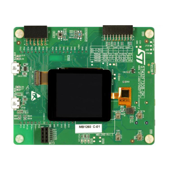
ST STM32F7308-DK User Manual (59 pages)
Discovery kit with STM32F730I8 MCU
Brand:
ST
| Category:
Microcontrollers
| Size: 3 MB
Table of Contents
Figure 1. STM32F7308-DK (Top View)
1
Figure 2. STM32F7308-DK (Bottom View)
1
Table of Contents
2
Features
7
Product Marking
8
System Requirements
8
Development Toolchains
8
Demonstration Software
9
Ordering Information
9
Table 1. Ordering Information
9
Hardware Layout and Configuration
10
Figure 3. Hardware Block Diagram
10
The STM32F7308-DK Discovery Kit Layout
11
Figure 4. STM32F7308-DK Top Layout
11
Figure 5. STM32F7308-DK Bottom Layout
12
The STM32F7308-DK Discovery Kit Mechanical Drawing
13
Figure 6. STM32F7308-DK Mechanical Drawing
13
Embedded ST-LINK/V2-1
14
Drivers
14
Figure 7. USB Composite Device
14
ST-LINK/V2-1 Firmware Upgrade
15
Power Supply
15
Supplying the Board through the ST-LINK USB Port (Default Setting)
15
Table 2. STM32F7308-DK Board Power Configuration
15
Supplying the Board through a Charger Connected to ST-LINK
16
Figure 8. CN8 (ST-LINK)
16
Cn8 (Usb_Stlink)
16
Supplying the Board from E5V (CN3 or CN12)
17
Supplying the Board from an External Power Supply through USB HS
17
Figure 10. CN8 (External 5V Supply)
17
Cn8 (Usb_Hs)
17
Supplying the Board from an External Power Supply through USB FS
18
Programming/Debugging When the Power Supply Is Not from
18
St-Link
18
Clock Sources
18
Cn8 (Usb_Fs)
18
Reset Sources
19
Audio
19
Usb Otg Hs
20
Usb Otg Fs
20
PSRAM Memory
21
Quad-SPI nor Flash Memory
21
Virtual COM Port
21
TFT LCD 240X240 Pixels
21
Capacitive Control Touch Panel
21
Buttons and Leds
22
Table 3. Control Port Assignment
22
Connectors
23
Arduino uno V3 Compatible Connectors
23
Figure 13. Wi-Fi Connector CN14 (Front View)
23
Table 4. Wi-Fi Extension Connector CN14
23
Wi-Fi ESP-01 Compatible Connector
23
Pmod™ and Stmod+ Connectors P2 and P1
24
Table 5. GPIO Assignment for Arduino Pins
24
Figure 14. Pmod™: Samtec SSW Connector (P2)
25
Pmod™ Connector P2
25
Table 6. GPIO Assignment for Pmod™ Pins
25
Table 7. Pmod™: SPI or UART Configuration Selection
25
Figure 15. Stmod+: Samtec SQT Connector (P1)
26
Stmod+ Connector P1
26
Table 8. GPIO Assignment for Stmod+ Pins
26
Table 9. Stmod+: SPI/UART Configuration Selection
26
Figure 16. TAG Connector (CN9)
27
TAG Connector CN9
27
Figure 17. USB OTG HS Micro-AB Connector CN19 (Front View)
28
Figure 18. USB OTG FS Micro-AB Connector CN18 (Front View)
28
Table 10. USB OTG HS Micro-AB Connector CN19
28
Table 11. USB OTG FS Micro-AB Connector CN18 (Front View)
28
USB OTG FS Micro-AB Connector
28
USB OTG HS Micro-AB Connector
28
Figure 19. LCD Frida Connector (Hirose FH26-29S-0.3SHW) CN17 (Front View)
29
LCD Frida Connector
29
Table 12. Pin Description of the LCD Frida Connector CN17
29
Control Touch Panel (CTP) Frida Connector
30
Figure 20. CTP Connector ((Hirose DF37NB-10DS-0.4V (5X)) CN16 (Front View)
30
Table 13. Pin Description of the CTP Connector CN16
30
Audio Line Connectors
31
Audio Stereo Speakers
31
Figure 21. USB Micro-B Connector CN1 (Front View)
31
Figure 22. Mechanical Drawing of the Audio Line Connector
31
Audio Line Input (Blue Jack) Connector
32
Audio Line Output (Green Jack) Connector
32
Table 15. Audio Line Output Connector CN5
32
Table 16. Audio Line Input Connector CN4
32
ST-LINK/V2-1 USB Micro-B Connector CN1
31
Table 14. USB Micro-B Connector CN1
31
Appendix A STM32F7308-DK Discovery Board I/O Assignment
33
Table 17. I/O Assignment
33
Appendix B Electrical Schematics
38
Figure 23. STM32F7308-DK Discovery Board Interconnections
39
Figure 27. PSRAM
39
Figure 24. ST-LINK/V2-1 with Support of SWD
40
Figure 25. STM32F730I8K6 Connections
41
Figure 26. Audio Codec WOLFSON and Audio Connectors
42
Figure 28. Quad-SPI Flash Memory (MICRON)
44
Figure 29. Arduino uno V3 Connectors
45
Figure 30. USB OTG HS PHY with Micro-AB Connector
46
Figure 31. USB OTG FS
47
Figure 32. LCD Frida
48
Figure 33. Wi-Fi, Leds and Push-Buttons
49
Figure 34. Fanout Board
50
Appendix C Pmod™ and Stmod+ Schematic Table
51
Table 18. Stmod+ Connector Signals
52
Appendix D Fanout Board
53
Figure 35. Stmod+ Fanout Module Plugged into P1 Connector
53
Mikroelektronika Mikrobus™ Compatible Connector (Fanout CN10 and CN11)
54
Wi-Fi Board Compatible Connector
54
Table 19. Description of the Mikrobus ™ Connector Pins
54
Table 20. Description of the ESP-01 Wi-Fi Board Connector Pins
54
D.2 ESP-01 Wi-Fi Board Compatible Connector
54
Compatible Connectors for the Grove Boards
55
Compatible Connector for I Compatible Connector for UART Grove Boards (Fanout CN2)
55
Grove Boards (Fanout CN3)
55
Table 21. Description of the I 2 C Grove Board Connector Pins (CN3)
55
Table 22. Description of the UART Grove Board Connector Pins (CN2)
55
D.3 Compatible Connectors for the Grove Boards
55
And Industry Canada (IC) Compliance Statements
56
F.1 Warning
57
Table 23. Document Revision History
58
Appendix E Federal Communications Commission (FCC)
56
Advertisement
Advertisement
Related Products
ST STM32F7508-DK
ST STM32F74 Series
ST STM32F75 Series
ST STM32F745VE
ST STM32F745IG
ST STM32F745ZE
ST STM32F746VG
ST STM32F746ZG
ST STM32F746IE
ST STM32F746VE
ST Categories
Motherboard
Computer Hardware
Microcontrollers
Control Unit
Controller
More ST Manuals
Login
Sign In
OR
Sign in with Facebook
Sign in with Google
Upload manual
Upload from disk
Upload from URL