ST STEVAL-PCC012V1 Manuals
Manuals and User Guides for ST STEVAL-PCC012V1. We have 2 ST STEVAL-PCC012V1 manuals available for free PDF download: User Manual

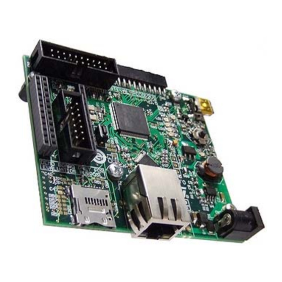
ST STEVAL-PCC012V1 User Manual (43 pages)
connectivity gateway, demonstration board
Brand: ST
|
Category: Computer Hardware
|
Size: 1 MB
Table of Contents
Advertisement

ST STEVAL-PCC012V1 User Manual (43 pages)
connectivity gateway, demonstration board
Table of Contents
Advertisement