Table of Contents
Advertisement
Quick Links
1
March 2010
Downloaded from
Elcodis.com
electronic components distributor
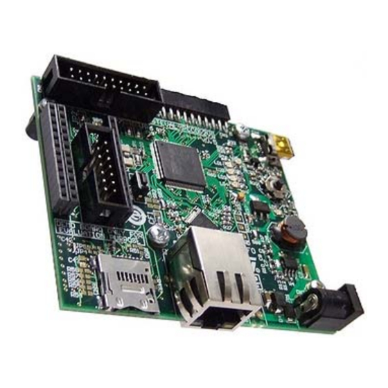
STEVAL-PCC012V1 STM32F107xx connectivity gateway,
Introduction
This user manual describes the implementation of the STEVAL-PCC012V1 demonstration
board. The STEVAL-PCC012V1 demonstration board is equipped with an Ethernet
interface, four digital/analog extension connectors (I
two different Wi-Fi modules, an OFDM PRIME power line networking extension connector
and a microSD™ Card socket with SPI interface. It also features a 5-way general purpose
joystick, four general purpose LEDs and two LEDs dedicated to user interface.
The demonstration board also includes digital/analog input/output connectors pinout
compatible with existing demonstration boards from STMicroelectronics™:
●
STEVAL-CCA021V1 - audio demonstration board (stereo DAC, Class-D amplifier)
●
STEVAL-MKI0xxV1 - MEMS demonstration boards (gyroscope, accelerometer) that
are compatible with 24 DIL socket
●
EVALST7590-1 - ST7590 "PRIME" board - narrow-band OFDM power line networking
PRIME compliant system-on-chip.
The demonstration board can be supplied from a standard DC power supply (7 - 35 V DC)
or directly using a 24 V DC industrial mains supply.
Figure 1.
STEVAL-PCC012V1
2
C, SPI, etc.), two footprint positions for
Doc ID 17009 Rev 1
UM0896
User manual
demonstration board
www.st.com
1/43
Advertisement
Table of Contents

Related Manuals for ST STEVAL-PCC012V1

Summary of Contents for ST STEVAL-PCC012V1
-
Page 1: Figure 1. Steval-Pcc012V1
STEVAL-PCC012V1 STM32F107xx connectivity gateway, demonstration board Introduction This user manual describes the implementation of the STEVAL-PCC012V1 demonstration board. The STEVAL-PCC012V1 demonstration board is equipped with an Ethernet interface, four digital/analog extension connectors (I C, SPI, etc.), two footprint positions for two different Wi-Fi modules, an OFDM PRIME power line networking extension connector and a microSD™... -
Page 2: Table Of Contents
Introduction ..........1 STEVAL-PCC012V1 key features ....... 6 Order code . - Page 3 UM0896 Contents U10 Wi-Fi module-2 debugging signals TXupd and RXupd ... 22 Ethernet RJ45 connectors CN5 ....... . 22 MicroSD Card connector CN9 .
- Page 4 List of tables UM0896 List of tables Table 1. Order code ............. . 7 Table 2.
- Page 5 Block diagram of STEVAL-PCC012V1 ........
-
Page 6: Steval-Pcc012V1 Key Features
STEVAL-PCC012V1 key features UM0896 STEVAL-PCC012V1 key features ● 1 x Ethernet RJ45 connectors (ST802RT1A) ● USB-OTG with 0.5 A onboard power supply ● General purpose extension connector with GPIOs, ADC, I C, SPI ● DC/DC converter L7986A (+24 V / +5 V) ●... -
Page 7: Order Code
UM0896 STEVAL-PCC012V1 key features Figure 3. STEVAL-MKI0xxV1 Refer to user manual UM0722 for details on how to use the STEVAL-CCA021V1. Order code Table 1. Order code Part number Note STEVAL-PCC012V1 STM32F107xx connectivity gateway STEVAL-CCA021V1 Audio demonstration board (stereo DAC, Class-D amplifier) -
Page 8: Block Diagram
Block diagram UM0896 Block diagram Figure 4. Block diagram of STEVAL-PCC012V1 8/43 Doc ID 17009 Rev 1 Downloaded from Elcodis.com electronic components distributor... -
Page 9: Demonstration Board Layout
UM0896 Demonstration board layout Demonstration board layout Figure 5. STEVAL-PCC012V1 - connector map JTAG audio extension analog USB-OTG digital extension JP2, 3 LEDs Crystal Joystick switch Reset Power line Test points network extension connector SB1, 2, 3 Ethernet options digital... -
Page 10: Configuration
Configuration UM0896 Configuration Ethernet An Ethernet PHY U5 is available on the board. It is connected through the media independent interfaces (MII, and reduced MII, RMII) to the Ethernet MACs of the STM32™ microcontroller. If the Ethernet PHY is used, the crystal resonator X2 must be chosen as STM32 clock source. -
Page 11: Power Supply
RMII and pulled low for MII during reset or power-up of the PHY. Power supply The STEVAL-PCC012V1 demonstration board is designed to be powered by a 24 V DC power supply from CN2, P2. The board is protected against overvoltage by D4 Transil™... -
Page 12: General Purpose 5-Way Joystick Sw1
Configuration UM0896 General purpose 5-way joystick SW1 A 5-way general purpose joystick is available on the top side of the board. Table 7. Joystick direction mapping STM32 pin mapping Joystick function PE14 Central button PE13 Direction right PE12 Direction left PE11 Direction down PE10... -
Page 13: I 2 C, Usart Signals Branching For Mems, Wi-Fi, Digital Audio
UM0896 Configuration C, USART signals branching for MEMS, Wi-Fi, digital audio and PLM Table 9. MEMS, Wi-Fi, PLM I C and USART signals branching Jumper Description Configuration PB7 is connected to MEMS extension connector as C SDA. The jumper must be set as shown: (3-pin resistor) PB7 is connected as USART1_RX to Wi-Fi 2 position 10 and PLM. -
Page 14: Analog Signals Branching For Mems
Configuration UM0896 Analog signals branching for MEMS Table 11. Analog signals branching of STM32 pins PA6 and PA7 to analog MEMS Jumper Description Configuration ADC_IN6 is connected to analog MEMS connector (out1 signal) R63 assembled (STM32 pin PA6 can be also configured as SPI MISO) (0 Ω... -
Page 15: Usb-Otg Configuration
UM0896 Configuration 5.10 USB-OTG configuration The STM32 microcontroller can distinguish between the host and device mode of the connected USB circuit by reading ID pin. It is possible to disconnect ID pin from USB connector CN4 (see Table 13). Table 13. USB-OTG configuration Jumper Description... -
Page 16: Wi-Fi Optional Modules
Configuration UM0896 5.12 Wi-Fi optional modules There are two positions for optional Wi-Fi modules: Table 14. Optional Wi-Fi modules configuration Position Interface used Note U9 - module-1 SPI1 + CS_Wi-Fi These signals are shared with I C for MEMS U10 - module-2 USART1 extension connector, refer to Section... -
Page 17: Connectors
UM0896 Connectors Connectors JTAG connector CN1 The CN1 connector allows to connect the STM32 microcontroller to a JTAG cable. Figure 7. JTAG connector pinout Table 17. JTAG connector signals Signal Signal Signal Signal +3.3 V JRTCK +3.3 V JTMS DBGRQ JTRST JTDO JTCK... -
Page 18: Analog/Digital Mems Extension Connector Cn6 And Cn8
Connectors UM0896 Table 18. Description of the I S audio connector pins of the TS4657 audio card Signal Signal Signal Signal Data format selection G1 gain select for Right channel mute for FMT2 for TS4657 TS2012 (PD3) TS2012 (PD4) (PE2) +3.3 V supply TS4657 SDAT I Standby for TS4962... -
Page 19: Digital Mems Connector Signals
UM0896 Connectors Table 19. Digital MEMS connector signals Signal (MEMS) Signal description N. C. High-pass filter reset, signal for gyroscope - MISO - MOSI Shared with I - SDA - CLK Shared with I - SCL CS_MEMS Chip select for the SPI device Power-down of the device Full scale of the measured range... -
Page 20: Power Line Networking Extension Connector Cn7
Connectors UM0896 Table 20. GPIO and analog MEMS connector signals Signal - the left half (GPIO) Signal - the right half (MEMS) +3.3 V +3.3 V +3.3 V +3.3 V GPIO (PD0) X - axis, or GYRO output-1 (PC0) GPIO (PD1) (ADC12_IN10) GPIO (PD13) GPIO (PB5) -
Page 21: Power Test Points
UM0896 Connectors Table 21. Connector CN7 for PLM, USART and SPI interface Signal Signal RTS_LV CTS_LV MDM_RESn_LV DFU_FORCE_LC Signals xxxx_LV mean, that these signals operate up to VCC_LV voltage level. VCC_LV is connected to 3.3 V. Power test points These three testing points allow to measure the power supply voltage. Table 22. -
Page 22: U10 Wi-Fi Module-2 Debugging Signals Txupd And Rxupd
Connectors UM0896 U10 Wi-Fi module-2 debugging signals TXupd and RXupd These two testing points allow to update the firmware of the optional Wi-Fi module-2. Table 24. U10 Wi-Fi module-2 debugging signals TXupd and RXupd Signal Signal description TXupd UART TX update signal RXupd UART RX update signal Ethernet RJ45 connectors CN5... -
Page 23: Microsd Card Connector Cn9
UM0896 Connectors MicroSD Card connector CN9 Figure 13. MicroSD Card connector CN9 Table 26. MicroSD Card connector CN9 Description Pin number Description CS_SDcard (PE7) MISO (SPI - PA6) MOSI (SPI - PA7) +3.3 V (SPI - PA5) SD_detect (PA4) Doc ID 17009 Rev 1 23/43 Downloaded from Elcodis.com... -
Page 24: Schematics
Connectors UM0896 6.10 Schematics Figure 14. Power supply 24/43 Doc ID 17009 Rev 1 Downloaded from Elcodis.com electronic components distributor... -
Page 25: Figure 15. Stm32 - Part 1(Inputs, Outputs, Clock, Reset)
UM0896 Connectors Figure 15. STM32 - part 1(inputs, outputs, clock, reset) Doc ID 17009 Rev 1 25/43 Downloaded from Elcodis.com electronic components distributor... -
Page 26: Figure 16. Stm32 - Part 2 (Jtag, Leds, Audio Extension Connector)
Connectors UM0896 Figure 16. STM32 - part 2 (JTAG, LEDs, audio extension connector) 26/43 Doc ID 17009 Rev 1 Downloaded from Elcodis.com electronic components distributor... -
Page 27: Figure 17. Stm32 - Part 3 (Joystick, Analog Decoupling, Dac_Fmt Signals)
UM0896 Connectors Figure 17. STM32 - part 3 (joystick, analog decoupling, DAC_FMT signals) Doc ID 17009 Rev 1 27/43 Downloaded from Elcodis.com electronic components distributor... -
Page 28: Figure 18. Ethernet - Part 1 (Phy Pinout)
Connectors UM0896 Figure 18. Ethernet - part 1 (PHY pinout) 28/43 Doc ID 17009 Rev 1 Downloaded from Elcodis.com electronic components distributor... -
Page 29: Figure 19. Ethernet - Part 2 (Overvoltage Protection, Phy Configuration)
UM0896 Connectors Figure 19. Ethernet - part 2 (overvoltage protection, PHY configuration) Doc ID 17009 Rev 1 29/43 Downloaded from Elcodis.com electronic components distributor... -
Page 30: Figure 20. Ethernet - Part 3 (Magnetics)
Connectors UM0896 Figure 20. Ethernet - part 3 (magnetics) 30/43 Doc ID 17009 Rev 1 Downloaded from Elcodis.com electronic components distributor... -
Page 31: Figure 21. Usb-Otg
UM0896 Connectors Figure 21. USB-OTG Doc ID 17009 Rev 1 31/43 Downloaded from Elcodis.com electronic components distributor... -
Page 32: Figure 22. Wi-Fi Module-1
Connectors UM0896 Figure 22. Wi-Fi module-1 32/43 Doc ID 17009 Rev 1 Downloaded from Elcodis.com electronic components distributor... -
Page 33: Figure 23. Wi-Fi Module-2
UM0896 Connectors Figure 23. Wi-Fi module-2 Doc ID 17009 Rev 1 33/43 Downloaded from Elcodis.com electronic components distributor... -
Page 34: Figure 24. Microsd Card
Connectors UM0896 Figure 24. MicroSD Card 34/43 Doc ID 17009 Rev 1 Downloaded from Elcodis.com electronic components distributor... -
Page 35: Figure 25. Mems Extension Connectors
UM0896 Connectors Figure 25. MEMS extension connectors Doc ID 17009 Rev 1 35/43 Downloaded from Elcodis.com electronic components distributor... -
Page 36: Power Supply Connectors Cn2, P2
Connectors UM0896 6.11 Power supply connectors CN2, P2 Figure 26. Power supply connector CN2 Table 27. Power supply connector CN2 Signal Signal 24 V DC Figure 27. Power supply connector P2 Table 28. Power supply connector P2 Signal 24 V DC 36/43 Doc ID 17009 Rev 1 Downloaded from... -
Page 37: Evaluation Software
The “CG demonstration” demonstrates the audio and Ethernet capabilities of the board. It also demonstrates the MEMS sensor data acquisition feature. To run the CG demonstration properly, the STEVAL-PCC012V1 and STEVAL-CCA021V1 must be interconnected. To perform MEMS sensor data acquisition, one of the compatible STEVAL-MKI0xxV1 boards should be connected. -
Page 38: Board Function Indication After Reset For Server/Clients Example
Evaluation software UM0896 Table 29. Board function indication after reset for server/clients example Function LED1 LED2 LED3 LED4 Static IP Client Server Figure 28. Connectivity Gateway Webserver demonstration 38/43 Doc ID 17009 Rev 1 Downloaded from Elcodis.com electronic components distributor... -
Page 39: Bom Of The Board
Protection diode SM6T33A RESET Button SW-PB Soldering bridge Soldbridge D1, D2, D3, D5 STPS3L40U ST: STPS3L40U Ethernet transformer con. J00-0086 R11, R14, R16, R18, R19, R20, R21, R22, R23, R48 10 kΩ 10k_0603 470 Ω 470R_0603 47 Ω 47R_0603 0 Ω... - Page 40 BOM of the board UM0896 Table 30. Bill of material (continued) Designator Value Comment R27, R29, R31, R33, R34, R35, R36, R37, R38, R39, 1.2 kΩ , 1 MΩ , 2 kΩ , 2.2 kΩ, 4.7 R40, R41, R42, R43, R44, R45, R46, R47, R49, R50, kΩ...
- Page 41 UM0896 BOM of the board Table 30. Bill of material (continued) Designator Value Comment L3, L4 MLS0805-4S4-300 RXupd, TXupd Update Joystick STM32F107VCT6_256K L5973D ST:L5973D STMPS2141STR USBLC6-2P6 ZG2100M Doc ID 17009 Rev 1 41/43 Downloaded from Elcodis.com electronic components distributor...
-
Page 42: Revision History
Revision history UM0896 Revision history Table 31. Document revision history Date Revision Changes 12-Mar-2010 Initial release. 42/43 Doc ID 17009 Rev 1 Downloaded from Elcodis.com electronic components distributor... - Page 43 No license, express or implied, by estoppel or otherwise, to any intellectual property rights is granted under this document. If any part of this document refers to any third party products or services it shall not be deemed a license grant by ST for the use of such third party products or services, or any intellectual property contained therein or considered as a warranty covering the use in any manner whatsoever of such third party products or services or any intellectual property contained therein.
Need help?
Do you have a question about the STEVAL-PCC012V1 and is the answer not in the manual?
Questions and answers