Sign In
Upload
Manuals
Brands
SICK Manuals
Safety Equipment
safeRS
SICK safeRS Manuals
Manuals and User Guides for SICK safeRS. We have
5
SICK safeRS manuals available for free PDF download: Operating Instructions Manual, Mounting Instructions
SICK safeRS Operating Instructions Manual (138 pages)
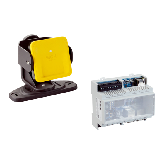
Safe Radar System
Brand:
SICK
| Category:
Radar
| Size: 4 MB
Table of Contents
Configuration
2
Table of Contents
3
1 Glossary of Terms
11
2 This Manual
12
Information on this Manual
12
Objectives of this Instruction Manual
12
Obligations with Regard to this Manual
12
Provided Documentation
12
Intended Users of this Instruction Manual
13
3 Safety
14
Safety Information
14
Safety Messages
14
Safety Symbols on the Product
14
Personnel Skills
14
Safety Assessment
15
Intended Use
15
EMC-Compliant Electrical Installation
15
General Warnings
15
Warnings for the Restart Prevention Function
16
Responsibility
16
Limits
16
Disposal
16
Conformity
17
Standards and Directives
17
Fcc
17
Srrc
18
Imda
18
Certificações ANATEL
18
Ncc
19
Icasa
19
Rohs2 China
20
National Restrictions
22
France and the United Kingdom
22
Japan
22
South Korea
22
Argentina
23
Mexico
23
Russian Federation
23
China
24
4 Get to Know Safers/Safers3 Mixed System
25
Safers/Safers3 Mixed System
25
Definition
25
Special Features
25
Main Components
26
Control - Sensor Communication
26
Control - Machinery Communication
26
Applications
26
Safers/Safers3 Mixed System Controls
27
Control Supported
27
Functions
27
Structures
28
System Status Leds
29
Fieldbus Status Leds
29
Inputs
30
Input Variable Behavior
30
SNS Input
31
Outputs
31
OSSD Diagnostic Checks
33
External Resistor for OSSD Outputs
33
Safers Sensor
34
Functions
34
Structure
34
Status LED
35
Safers3 Designer Application
35
Functions
35
Safers3 Designer Application Usage
35
Authentication
36
Main Menu
36
Fieldbus Communication
37
Fieldbus Support
37
Communication with the Machinery
37
Data Exchanged through Fieldbus
38
MODBUS Communication
39
MODBUS Support
39
MODBUS Communication Enabling
39
Data Exchanged through MODBUS
39
System Configuration
40
Dynamic System Configuration
40
Dynamic System Configuration Activation
40
Dynamic Configuration through the Digital Inputs
41
Dynamic Configuration through the Safety Fieldbus
42
Safe Configuration Switch
42
5 Functioning Principles
43
Sensor Functioning Principles
43
Introduction
43
Factors that Influence the Sensor Field of View and Object Detection
43
Factors that Influence the Reflected Signal
43
Detected and Missed Objects
43
Protective Fields
44
Introduction
44
Protective Field Parameters
44
Protective Fields Dependency and Detection Signal Generation
45
System Category (According to en ISO 13849)
46
System Safety Degree
46
PL D, Category 2 Configuration
46
PL D, Category 3 Configuration
47
Safety Working Modes and Safety Functions
48
Introduction
48
Safety Working Modes
48
Safety Working Modes Examples
49
Safety Working Mode: both (Default)
53
Introduction
53
Safety Function: Access Detection
53
Safety Function: Restart Prevention
54
Safety Working Mode: Always-On Access Detection
54
Safety Function: Access Detection
54
TOFF Parameter
54
Safety Working Mode: Always-On Restart Prevention
55
Safety Function: Restart Prevention
55
Features of the Restart Prevention Function
55
Cases of Non-Guaranteed Function
55
Types of Managed Restart
56
Precautions for Preventing Unexpected Restarting
57
Configure the Restart Prevention Function
57
Muting
58
Description
58
Muting Enabling
58
Muting Activation Conditions
58
Enable Muting Signal Characteristics
59
Muting Status
59
Anti-Tampering Functions: Anti-Rotation Around Axes
59
Anti-Rotation Around Axes
59
Enable the Anti-Rotation Around Axes Function
60
When to Enable
60
Checks When the Anti-Rotation Around Axes Function Is Disabled
60
Anti-Tampering Functions: Anti-Masking
61
Masking Signal
61
Environment Memorization Process
61
Causes of Masking
61
Masking Signal When the System Is Turned on
61
Sensitivity Level
62
Checks When the Anti-Masking Function Is Disabled
62
When to Disable
63
Multi-Control Synchronization
63
Introduction
63
Network Topology
63
Trigger Source
64
Required Signal
64
Enable the Multi-Control Synchronization Function
64
Electrical Connections
66
6 Sensor Position
68
Basic Concepts
68
Determining Factors
68
Sensor Installation Height
68
Sensor Inclination
68
Sensor Field of View
68
Types of Field of View
68
Features of the 50° Field of View
69
Areas and Dimensions of the Field of View
69
Dimensions of the 110° Field of View
69
Dimensions of the 50° Field of View
70
Sensitivity
70
Dangerous Area Calculation
70
Introduction
70
Sensor Height ≤ 1 M
71
Sensor Height > 1 M
72
Calculation of Position for Sensor Height ≤ 1 M
72
Introduction
72
Overview of Possible Installation Configurations
73
Legend
74
Configuration 1
75
Configuration 3
77
Calculate the Real Detection Distance
78
Calculation of Position for Sensor Height > 1 M
78
Introduction
78
110° Field of View
79
Calculate the Real Detection Distance
79
Outdoor Installations
80
Position Exposed to Precipitation
80
Recommendations for Covering the Sensor
80
Recommendations for Positioning the Sensor
80
Position Not Exposed to Precipitation
81
7 Installation and Use Procedures
82
Before Installation
82
Materials Required
82
Operating System Required
82
Install the Safers3 Designer Application
82
Initiate Safers/Safers3 Mixed System
83
Install and Configure Safers/Safers3 Mixed System
83
Install the Control
83
Synchronize the Controls
83
Define the Area to be Monitored
84
Configure the Inputs and Outputs
84
Install Sensors on the Floor
84
Install the Sensors on the Machinery
86
Connect the Control to the Sensors
87
Assign the Node Ids
87
Chain Examples
88
Save and Print the Configuration
88
Set the Control Ethernet Parameters
89
Validate the Safety Functions
89
Validation
89
Validate the Access Detection Function
89
Example of Access Points
90
Validate the Restart Prevention Function
91
Example of Stopping Points
91
Validate the System with Safers3 Designer
92
Troubleshooting Validation
92
Manage the Configuration
92
Configuration Checksums
92
Configuration Reports
93
Change the Configuration
93
Back up the Configuration
94
Load a Configuration
94
Display Previous Configurations
94
Other Functions
94
Change Language
94
Locate the Area with Detected Motion
94
Change the Admin Password
94
Restore Factory Default Settings
95
Identify a Sensor
95
Change Network Parameters
95
Change Modbus Parameters
95
Change Fieldbus Parameters
95
Set Labels
95
8 Maintenance and Troubleshooting
96
Troubleshooting
96
Control LED
96
Sensor LED
98
Other Problems
99
Event Log Management
100
Introduction
100
Download the System Log
100
Log File Sections
100
Log Line Structure
100
Timestamp (Seconds Counter from the Latest Boot)
101
Timestamp (Absolute/Relative Value)
101
Event Description
101
Log File Example
102
Event List
103
Verbosity Level
103
Verbosity Level for Detection Access and Exit Events
104
INFO Events
104
System Boot
104
System Configuration
105
Factory Reset
105
Stop Signal
105
Restart Signal
105
Detection Access
105
Detection Exit
106
Dynamic Configuration in Use
106
Muting Status
106
Fieldbus Connection
106
MODBUS Connection
107
Session Authentication
107
Validation
107
Log Download
107
ERROR Events (Control)
108
Introduction
108
Temperature Errors (TEMPERATURE ERROR)
108
Control Voltage Errors (POWER ERROR)
108
Peripheral Error (PERIPHERAL ERROR)
108
Configuration Errors (FEE ERROR)
108
Output Errors (OSSD ERROR)
109
Flash Errors (FLASH ERROR)
109
Dynamic Configuration Error (DYNAMIC CONFIGURATION ERROR)
109
Internal Communication Error (INTERNAL COMMUNICATION ERROR)
109
Input Redundancy Error (INPUT REDUNDANCY ERROR)
109
Fieldbus Error (FIELDBUS ERROR)
109
RAM Error (RAM ERROR)
109
Sensor Configuration Errors (SENSOR CONFIGURATION ERROR)
110
ERROR Events (Sensor)
110
Introduction
110
Radar Signal Errors (Signal Error)
110
Temperature Errors (TEMPERATURE ERROR)
110
Sensor Voltage Errors (POWER ERROR)
110
Anti-Tampering Sensor (ACCELEROMETER ERROR)
111
Peripheral Error (PERIPHERAL ERROR)
111
ERROR Events (CAN Bus)
111
Introduction
111
CAN Errors (CAN ERROR)
111
Cleaning and Spare Parts
112
Cleaning
112
Spare Parts
112
9 Technical References
113
Technical Data
113
General Specifications
113
Safety Parameters
113
Ethernet Connection (if Available)
114
Control Features
115
Sensor Features
116
CAN Bus Cables Recommended Specifications
117
Side Screw Specifications
117
Bottom Screws Specifications
117
Terminal Blocks and Connector Pin-Outs
118
Digital Inputs and Outputs Terminal Block
118
Voltage and Current Limits for Digital Inputs
119
Power Supply Terminal Block
119
CAN Bus Terminal Block
119
Connectors M12 CAN Bus
120
Electrical Connections
121
Connection of Safety Outputs to the Machinery Control System
121
Connection of Safety Outputs to an External Safety Relay
122
Connection of Stop Signal (Emergency Button)
123
Connection of Restart Signal
124
Connection of the Muting Input and Output (One Group of Sensors)
125
Connection of the Muting Input and Output (Two Groups of Sensors)
126
Detection Signal 2 Connection
127
Diagnostic Output Connection
128
Multi-Control Synchronization
129
Configuration Application Parameters
129
Parameter List
129
Digital Input Signals
132
Stop Signal
132
Muting (With/Without Pulse)
132
Advertisement
SICK safeRS Operating Instructions Manual (92 pages)
Safe radar system
Brand:
SICK
| Category:
Safety Equipment
| Size: 4 MB
Table of Contents
Table of Contents
3
1 Glossary of Terms
9
2 This Manual
10
Information on this Manual
10
Scope
10
Obligations with Regard to this Manual
10
Supplied Documentation
10
Intended Users of this Instruction Manual
10
3 Safety
11
Safety Information
11
Safety Messages
11
Safety Symbols on the Product
11
Personell Skills
11
Foreseen Use
12
General Warnings
12
Warnings for the Restart Prevention Funktion
12
Responsibility
13
Limits
13
Conformity
13
Directives and Standards
13
Fcc
13
Industry Canada
14
Srrc
14
Imda
14
Ncc
14
Icasa
15
ROHS2 China
15
National Restrictions
16
France and the United Kingdom
16
Japan
16
South Korea
17
Argentina
17
Mexico
17
China
17
4 Get to Know Safers
18
Safers
18
Safety Functions
18
Inputs and Outputs
18
Special Features
18
Main Components
18
Controller - Sensors Communication
19
Application Options
19
Safers Control
19
Functions
19
Structure
19
LED System State
20
Inputs and Outputs Status LED
20
Safety Outputs
20
Safety Outputs Status
20
Auxiliary Outputs
20
Auxiliary Outputs Status
21
Digital Inputs
21
SNS Input
21
Safers Sensor
21
Functions
21
Structure
22
Status LED
22
Safers Designer
22
Functions
22
Access
23
Main Menu
23
5 Functioning Principles
24
Sensor Functioning Principles
24
Introduction
24
Factors that Influence the Reflected Signal
24
Signaled and Missed Objects
24
Safety Functions
24
Default Function
24
Selectable Safety Functions
24
Access Detection
25
Description
25
Pre-Alarm Area
25
Restart Prevention Function
25
Function Limits
26
Cases in Which Function Is Not Guaranteed
26
Types of Managed Restart
27
Safety Precautions to Prevent Unintentional Restart
27
Enable the Restart Prevention Function
28
Muting Function
28
Description
28
Activation of the Muting Function
28
Example of Sensors - Groups Association
29
Example of Digital Inputs - Groups Association
29
Signal Characteristics for Muting Activation
29
Muting Function State
29
Manipulation Protection Functions: Anti-Rotation Around Axes
30
Anti-Rotation Around Axes
30
Deactivating Anti-Rotation Around Axes
30
Checks with Deactivated Anti-Rotation Around Axes Function
30
Necessity of Deactivation
31
Manipulation Protection Functions: Masking Protection
31
Masking Signal
31
Environment Memorization Process
31
Causes of Masking
31
Masking Signal When the System Is Turned on
31
Sensitivity Levels
31
Checks with the Masking Protection Function Deactivated
32
Necessity of Deactivation
32
6 Sensor Position
33
Basic Concepts
33
Determining Factors
33
Sensor Installation Height
33
Sensor Inclination
33
Sensor Field of Vision
33
Types of Field of Vision
33
Features of the 50° Field of Vision
34
Areas and Dimensions of the Field of Vision
34
Sensitivity
35
Dangerous Area Calculation
35
Introduction
35
Height of Sensor ≤ 1 M
35
Sensor Height > 1 M
36
Calculation of the Position at a Sensor Height ≤ 1 M
37
Introduction
37
Overview of the Configuration Options Regarding Installation
37
Legend
38
Configuration 1
38
Configuration 2
39
Configuration 3
40
Calculating the Actual Alarm Distance
41
Calculation of Position for Sensor Height > 1 M
41
Introduction
41
Legend
42
110° Field of Vision
42
Calculating the Actual Alarm Distance
43
Outdoor Installation
43
Places Influenced by Precipitation
43
Recommendations for Covering Sensor
43
Recommendations for the Position of the Sensor
44
Places Not Influenced by Precipitation
44
7 Application Options
45
Overview of Application Options
45
Comparison of Supported Application Options
45
Linear Barrier (Complete Restart Prevention)
45
Distance between Sensors and Number of Sensors
45
Tolerance Area
46
Distance of Sensors and Tolerance Area
46
Side Areas and Faulty Alarms
46
Calculation of the Monitored Area
47
Example of a Monitored Area with an Odd Number of Sensors
47
Example of a Monitored Area with an Even Number of Sensors
48
Linear Barrier (Limited Restart Prevention)
48
Distance between Sensors and Number of Sensors
48
Tolerance Area
49
Distance of Sensors and Tolerance Area
49
Lateral Physical Guards and Faulty Alarms
49
Blind Spots
49
Restart Prevention Function Limits
50
Calculation of the Monitored Area
50
Example of Monitored Area Without Pre-Alarm Area
51
Example of Monitored Area with Pre-Alarm Area
51
Other Application Options
51
Types of Application Options
51
Calculation of the Monitored Area
51
Examples
52
8 Installation and Use Procedures
54
Before Installation
54
Materials Required
54
Operating System Requirements
54
Install the Safers Designer
54
Initiate Safers
54
Install and Configure Safers
55
Install the Controller
55
Define the Working Frequency of the Sensors
55
Define the Area to be Monitored
55
Configure the Auxiliary Inputs and Outputs
56
Install Sensors on the Floor
56
Install the Sensors on the Machinery
57
Connect the Controller to the Sensors and Assign the Ids
58
Chain Examples
60
Save and Print the Configuration
60
Installation of the Lateral Physical Guards
60
Validate Safety Functions
60
Validation
60
Test of Access Detection
61
Example of Access Points
61
Validate the Restart Prevention Function
61
Examples of Stopping Points
62
Validate the System with Safers Designer
62
Solving Problems Connected to the Check
62
Manage the Configuration
63
Configuration Reports
63
Change the Configuration
63
Execution of Configuration Back-Up
64
Loading a Configuration
64
Display of Previous Configurations
64
Other Functions
64
Changing the Language
64
Identifying the Area Where a Movement was Detected
64
Changing the Access Password
64
Restore Factory Default Settings
64
Identify a Sensor
65
9 Maintenance and Rectification of Failures
66
Rectification of Failures
66
Sensor LED
66
Controller LED
66
Other Problems
67
System Log
67
Event Log Management
67
Download System Log
68
Radar Signal Errors (SIGNAL ERROR)
68
CAN Errors (CAN ERROR)
68
Temperature Errors (TEMPERATURE ERROR)
68
Relay Errors (RELAY ERROR)
69
Sensor/Controller Voltage Errors (POWER ERROR)
69
Sensor Inclination Errors (ACCELEROMETER ERROR)
70
Peripheral Error (PERIPHERAL ERROR)
70
Configuration Error (FEE ERROR)
70
System Boot (SYSTEM BOOT)
70
System Safety Alarm
70
Cleaning and Spare Parts
70
Cleaning
70
Spare Parts
70
Periodical Tests
71
Test
71
Periodical Test with Safers Designer
71
Execution of a Periodic Test with Safers Designer
71
Display of Reports for the Executed Tests
71
Updates
71
Download of Software Updates
71
10 Decommissioning
72
Disposal
72
11 Technical References
73
Technical Data
73
General Specifications
73
Controller Features
73
Sensor Features
74
CAN Bus Cables Specifications
75
Side Screws Specifications
75
Specifications of Lower Screws
76
Terminal Blocks and Connectors Pin-Outs
78
Safety Outputs Terminal Block
78
Auxiliary Outputs Terminal Block
78
Digital Inputs Terminal Block
78
Voltage and Current Limits for Digital Inputs
79
Power Supply Terminal Block
79
CAN Bus Terminal Block
79
Connectors M12 CAN Bus
80
Electrical Connections
80
Connection of Safety Outputs to the Machinery Control System
80
Connection of Safety Outputs to an External Safety Relay
81
Connection of Emergency Button
81
Connection of the Restart Enable Pushbutton
82
Connection of the Input and Output for the Muting Function (One Sensor Group)
82
Connection of the Input and Output for the Muting Function (Two Sensor Groups)
83
Pre-Alarm Output Connection
83
Connection of Failure Output
84
Default Values
84
Parameter List
84
Digital Input Signals
86
Stop Signals
86
Muting (With/Without Clock)
86
Restart Signal
89
SICK safeRS Operating Instructions Manual (72 pages)
Radar Safety System
Brand:
SICK
| Category:
Safety Equipment
| Size: 2 MB
Table of Contents
Table of Contents
3
1 Glossary of Terms
9
2 This Manual
10
Information on this Manual
10
Scope
10
Obligations with Regard to this Manual
10
Intended Users of this Instruction Manual
10
3 Safety
11
Safety Information
11
Safety Messages
11
Personell Skills
11
Foreseen Use
11
General Warnings
12
Warnings for the Restart Prevention Funktion
12
Responsibility
12
Limits
12
Conformity
12
Directives and Standards
12
Declaration of Conformity and Certifications
13
FCC Certification
13
National Restrictions
13
France and the United Kingdom
13
Japan
14
Korea
14
Argentina
14
Mexico
14
China
15
4 Get to Know Safers
16
Safers
16
Description
16
Inputs and Outputs
16
Special Features
16
Main Components
16
Controller - Sensors Communication
17
Applications
17
Safers Control
17
Functions
17
Structure
17
Sensors Status LED
18
Inputs and Outputs Status LED
18
Safety Outputs
18
Safety Outputs Status
18
Auxiliary Outputs
18
Auxiliary Outputs Status
19
Digital Inputs
19
SNS Input
19
Safers Sensor
19
Functions
19
Structure
20
Status LED
20
Safers Designer
20
Functions
20
Access
20
Main Menu
21
Configuration Report
21
5 Functioning Principles
22
Sensor Functioning Principles
22
Introduction
22
Factors that Influence the Reflected Signal
22
Signaled and Missed Objects
22
Detection Function
22
Description
22
Pre-Alarm Area
23
Restart Prevention Function
23
Description
23
Function Limits
23
Types of Managed Restart
23
Precautions for Preventing Automatic Restarting
24
Enable the Restart Prevention Function
24
Muting
24
Description
24
Muting Enabling
24
Example of Sensors - Groups Association
25
Example of Digital Inputs - Groups Association
25
Muting Status
25
Tamper-Proof Functions
25
Tampering Signal
25
Masking Signal
25
Masking Conditions
26
Environment Memorization Process
26
Causes of Masking
26
Masking Signal When the System Is Turned on
26
Disable Masking Signals
26
Inspections with Masking Signals Disabled
26
When to Disable
27
6 Sensor Position
28
Basic Concepts
28
Determining Factors
28
Sensor Installation Height
28
Sensor Inclination
28
Sensor Field of Vision
28
Types of Field of Vision
28
Features of the 50° Field of Vision
29
Areas and Dimensions of the Field of Vision
29
Dimensions of the 110° Field of Vision
29
Dimensions of the 50° Field of Vision
29
Sensitivity
30
Calculation of Position for Sensor Height < 1 M
30
Introduction
30
Overview of Possible Installation-Inclination Configurations
30
110° Field of Vision
30
50° Field of Vision
31
Legend
31
Configuration 1 (Sensor Upwards)
31
50° Field of Vision
32
Configuration 2 (Straight Sensor)
32
50° Field of Vision
33
Configuration 3 (Sensor Downwards)
33
50° Field of Vision
34
Calculation of Position for Sensor Height > 1 M
34
Introduction
34
Legend
34
50° Field of Vision
35
Dangerous Area Calculation
35
Introduction
35
Sensor Height < 1 M
36
7 Applications
38
Applications Overview
38
Comparison of the Managed Applications
38
Linear Barrier (Complete Restart Prevention)
38
Distance between Sensors and Number of Sensors
38
Tolerance Area
39
Distance of Sensors and Tolerance Area
39
Side Areas and False Alarms
39
Calculation of the Monitored Area
40
Example of a Monitored Area with an Odd Number of Sensors
40
Example of a Monitored Area with an Even Number of Sensors
41
Linear Barrier (Limited Restart Prevention)
41
Distance between Sensors and Number of Sensors
41
Tolerance Area
42
Distance of Sensors and Tolerance Area
42
Side Guards and False Alarms
42
Blind Spots
42
Restart Prevention Function Limits
43
Calculation of the Monitored Area
43
Example of Monitored Area Without Pre-Alarm Area
43
Example of Monitored Area with Pre-Alarm Area
44
Other Applications
44
Types of Applications
44
Calculation of the Monitored Area
44
Examples
45
8 Installation and Use Procedures
46
Before Installation
46
Materials Required
46
Install the Safers Designer
46
Initiate Safers
46
Install and Configure Safers
46
Install the Controller
46
Define the Working Frequency of the Sensors
47
Define the Area to be Monitored
47
Configure the Auxiliary Inputs and Outputs
47
Save and Print the Configuration
48
Install Sensors on the Floor
48
Install the Sensors on the Machinery
49
Connect the Controller to the Sensors and Assign the Ids
50
Chain Examples
50
Install the Side Guards
51
Validate Safety Functions
51
Validation
51
Validate the Detection Function
51
Example of Access Points
52
Validate the Restart Prevention Function
52
Examples of Stopping Points
52
Validate the System with Safers Designer
52
Troubleshooting Validation
53
Manage the Configuration
53
Change the Configuration
53
Export/Import the Configuration
54
Other Functions
54
Change the Access Password
54
Reset the Access Password
54
Restore Factory Default Settings
54
Identify a Sensor
54
9 Maintenance and Troubleshooting
55
Troubleshooting
55
Sensor LED
55
Controller LED
55
Other Problems
56
System Log
56
Introduction
56
Download System Log
56
Radar Signal Errors (SIGNAL ERROR)
56
CAN Errors (CAN ERROR)
57
Temperature Errors (TEMPERATURE ERROR)
57
Relay Errors (RELAY ERROR)
57
Sensor/Controller Voltage Errors (POWER ERROR)
57
Sensor Inclination Errors (ACCELEROMETER ERROR)
58
Peripheral Error (PERIPHERAL ERROR)
58
System Boot (SYSTEM BOOT)
58
Sensor Voltage
58
Controller Voltage
58
Cleaning and Spare Parts
58
Cleaning
58
Spare Parts
58
Periodical Tests
59
Test
59
Periodical Test with Safers Designer
59
Perform the Test with Safers Designer
59
Display the Performed Test Reports
59
Updates
59
Download Updates
60
10 Decommissioning
61
Disposal
61
11 Technical References
62
Technical Data
62
General Specifications
62
Controller Features
62
Sensor Features
63
CAN Bus Cables Specifications
64
Side Screws Specifications
64
Terminal Blocks and Connectors Pin-Outs
65
Safety Outputs Terminal Block
65
Auxiliary Outputs Terminal Block
65
Digital Inputs Terminal Block
66
Voltage and Current Limits for Digital Inputs
66
Power Supply Terminal Block
66
CAN Bus Terminal Block
66
Connectors M12 CAN Bus
67
Electrical Connections
67
Connection of Safety Outputs to the Machinery Control System
67
Connection of Safety Outputs to an External Safety Relay
68
Connection of Emergency Button
68
Connection of Restart Enable Button
69
Connection of the Muting Input and Output (One Group of Sensors)
69
Connection of the Muting Input and Output (Two Groups of Sensors)
70
Pre-Alarm Output Connection
70
Faulty Output Connection
71
Advertisement
SICK safeRS Mounting Instructions (44 pages)
Safe Radar System
Brand:
SICK
| Category:
Radar
| Size: 1 MB
Table of Contents
Allgemeine Sicherheitshinweise
3
Installation
12
General Warnings
23
About this Document
24
Component Structure
25
Install the Application
32
SICK safeRS Mounting Instructions (14 pages)
Radar Safety System
Brand:
SICK
| Category:
Safety Equipment
| Size: 0 MB
Table of Contents
Zu diesem Dokument
3
Zu Ihrer Sicherheit
3
About this Document
9
Safety Information
9
Device Overview
9
Advertisement
Related Products
SICK safe Brake Assist
SICK sBot Speed CIP KU
SICK sBot Stop
SICK sBot Speed - YA
SICK SRS50S
SICK SRM50S
SICK STL70S
SICK Safe Entry Exit
SICK safeRS3
SICK safeVisionary2
SICK Categories
Accessories
Security Sensors
Measuring Instruments
Scanner
Barcode Reader
More SICK Manuals
Login
Sign In
OR
Sign in with Facebook
Sign in with Google
Upload manual
Upload from disk
Upload from URL