Sign In
Upload
Manuals
Brands
Pfeiffer Vacuum Manuals
Water Pump
HIPACE 1200 I
Pfeiffer Vacuum HIPACE 1200 I Manuals
Manuals and User Guides for Pfeiffer Vacuum HIPACE 1200 I. We have
2
Pfeiffer Vacuum HIPACE 1200 I manuals available for free PDF download: Operating Instructions Manual
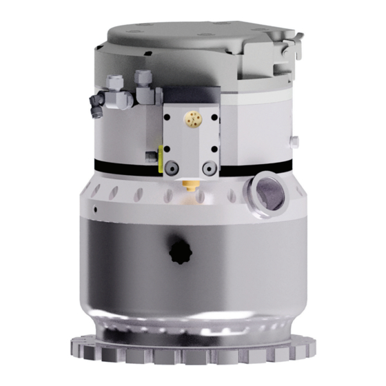
Pfeiffer Vacuum HIPACE 1200 I Operating Instructions Manual (148 pages)
Turbopump prepared for temperature management system
Brand:
Pfeiffer Vacuum
| Category:
Water Pump
| Size: 16 MB
Table of Contents
Deutsch
3
Table of Contents
3
Zielgruppe
8
Anweisungen IM Text
8
Konventionen
8
Zu dieser Anleitung
8
Varianten
8
Mitgeltende Dokumente
8
Gültigkeit
8
Piktogramme
9
Aufkleber auf dem Produkt
9
Abkürzungen
10
Abb. 1: Position der Aufkleber auf dem Produkt
10
Markennachweis
11
Sicherheit
12
Allgemeine Sicherheitshinweise
12
Sicherheitshinweise
12
Sicherheitsmaßnahmen
17
Bestimmungsgemäße Verwendung
18
Einsatzgrenzen des Produkts
18
Personenqualifikation Sicherstellen
19
Vorhersehbarer Fehlgebrauch
19
Personenqualifikation
19
Personenqualifikation bei Wartung und Reparatur
20
Mit Pfeiffer Vacuum Weiterbilden
20
Abb. 2: Aufbau Hipace 1200 I | IU
21
Antrieb
21
Rotorlager
21
Kühlung
21
Funktionsmerkmale
21
Produktbeschreibung
21
Produkt Identifizieren
22
Produkttypen
22
Produktmerkmale
22
Lieferumfang
22
Transport und Lagerung
23
Transport
23
Abb. 3: Anschlagpunkte für den Vertikalen Transport der Turbopumpe ohne Verpa
24
Transport in Vertikaler Raumlage
24
Transport in Horizontaler Raumlage
24
Lagerung
25
Abb. 4: Anschlagpunkte für den Horizontalen Transport der Turbopumpe ohne Ver
25
Installation
26
Vorbereitende Arbeiten
26
Hochvakuumseite Anschließen
27
Anforderungen für die Auslegung des Gegenflansches
27
Erdbebensicherheit Berücksichtigen
27
Splitterschutz oder Schutzgitter Verwenden
28
Dämpfungskörper Verwenden
28
Abb. 5: Beispiel: Sicherung gegen Verschieben und Kippen durch Externe Erschüt
28
Einbaulagen
29
Abb. 6: Einbaulagen der Standardversion, Aufrecht
29
Abb. 7: Einbaulagen der U-Version, Überkopf
29
Abb. 8: Ausrichtung des Vorvakuumanschlusses bei Horizontaler Einbaulage
29
Abb. 9: Flanschverbindung ISO-K zu ISO-K, Klammerschraube
30
ISO-K Flansch an ISO-F Befestigen
30
ISO-K Flansch an ISO-K Befestigen
30
Abb. 10: Flanschverbindung ISO-K zu ISO-F, Sechskantschraube und Gewindeboh
31
Abb. 11: Flanschverbindung ISO-K zu ISO-F, Stiftschraube und Gewindebohrung
31
Abb. 12: Flanschverbindung ISO-K zu ISO-F, Stiftschraube und Durchgangsbohrung
31
ISO-F Flansch an ISO-F Befestigen
32
Abb. 13: Flanschverbindung ISO-F, Sechskantschraube und Gewindebohrung
32
Abb. 14: Flanschverbindung ISO-F, Sechskantschraube und Durchgangsbohrung
32
Abb. 15: Flanschverbindung ISO-F, Stiftschraube und Gewindebohrung
32
Betriebsmittel Einfüllen
33
Abb. 16: Flanschverbindung ISO-F, Stiftschraube und Durchgangsbohrung
33
Vorvakuumseite Anschließen
34
Abb. 17: Position der Einfüllschrauben Abhängig von der Einbaulage. Beispiel: Stan
34
Abb. 18: Position der Einfüllschrauben Abhängig von der Einbaulage. Beispiel: U-Ver
34
Kühlwasserversorgung Anschließen
35
Abb. 19: Beispiel für den Vorvakuumanschluss
35
Kühlwasseranschluss mit Schlauchtüllen Herstellen
36
Kühlwasseranschluss mit Rohrverschraubungen Herstellen
37
Abb. 20: Kühlwasseranschluss mit Schlauchtüllen
37
Zubehör Anschließen an Turbopumpen mit TMS
38
Abb. 21: Kühlwasseranschluss mit Rohrverschraubungen
38
Vakuumpumpe Erden
39
Elektrische Versorgung Anschließen
39
Elektrischen Anschluss Herstellen
40
Abb. 22: Beispiel: Anschluss des Erdungskabels
40
Elektrische Schutzmaßnahmen Einrichten
41
Betrieb
42
Inbetriebnahme
42
Betriebsarten
43
Betrieb ohne Bedieneinheit
43
Betrieb über Anschluss "E74
43
Betrieb über Multifunktionsanschluss "Remote
43
Betrieb über Pfeiffer Vacuum Steuergerät
43
Turbopumpe Einschalten
44
TMS Anschluss
45
Ablaufbeschreibung TMS
45
Stellbefehle
45
Nach Umbauen mit TMS Betreiben
45
Betriebsüberwachung
46
Betriebsanzeige über LED
46
Temperaturüberwachung
46
Ausschalten und Fluten
46
Ausschalten
47
Fluten
47
Wartungsintervalle Und- Zuständigkeiten
48
Allgemeine Wartungshinweise
48
Wartung
48
Betriebsmittel Wechseln
49
Betriebsmittel Ablassen
49
Abb. 23: Beispiele: Betriebsmittel Ablassen bei Standard- und U-Versionen
49
Betriebsmittel Einfüllen
50
Abb. 24: Position der Einfüllschrauben Abhängig von der Einbaulage. Beispiel: Stan
50
Antriebselektronik Austauschen
51
Abb. 25: Position der Einfüllschrauben Abhängig von der Einbaulage. Beispiel: U-Ver
51
Abb. 26: Ausbau der Antriebselektronik
52
Antriebselektronik Montieren
52
Antriebselektronik Demontieren
52
Drehzahlvorgabe Bestätigen
53
Abb. 27: Befestigung der Antriebselektronik
53
Wiedermontage der Rohrverschraubungen
54
Rohrverschraubungen Demontieren
54
Rohrverschraubungen Montieren
54
Abb. 28: Rohrverschraubungen Demontieren
54
Abb. 29: Rohrverschraubungen Montieren
55
Außerbetriebnahme
56
Stillsetzen für Längere Zeit
56
Wiederinbetriebnahme
56
Recycling und Entsorgung
57
Allgemeine Entsorgungshinweise
57
Turbopumpe Entsorgen
57
Störungen
58
Servicelösungen von Pfeiffer Vacuum
61
Abb. 30: Ersatzteile Hipace 1200 I | IU
63
Ersatzteile
63
Zubehör
64
Zubehörinformationen
64
Zubehör Bestellen
64
Technische Daten und Abmessungen
66
Allgemeines
66
Technische Daten
66
Medienberührende Werkstoffe
68
Abb. 32: Hipace 1200 IU | DN 200 ISO-F
69
Abb. 31: Hipace 1200 I | DN 200 ISO-F
69
Abb. 33: Hipace 1200 I | DN 200 ISO-K
70
Abb. 34: Hipace 1200 IU | DN 200 ISO-K
70
English
73
About this Manual
78
Applicable Documents
78
Conventions
78
Instructions in the Text
78
Target Group
78
Validity
78
Variants
78
Pictographs
79
Stickers on Product
79
Abbreviations
80
Tbl. 2: Abbreviations Used in this Document
81
Trademark Proof
81
General Safety Information
82
Safety
82
Safety Instructions
82
Safety Precautions
87
Foreseeable Improper Use
88
Limits of Use of the Product
88
Proper Use
88
Tbl. 3: Permissible Ambient Conditions
88
Ensuring Personnel Qualification
89
Personnel Qualification
89
Advanced Training with Pfeiffer Vacuum
90
Personnel Qualification for Maintenance and Repair
90
Cooling
91
Drive
91
Fig. 2: Hipace 1200 I | IU Design
91
Functional Properties
91
Product Description
91
Rotor Bearing
91
Identifying the Product
92
Product Features
92
Product Types
92
Scope of Delivery
92
Tbl. 4: Product Designation of Pfeiffer Vacuum Hipace Turbopumps
92
Tbl. 5: Turbopump Features
92
Tbl. 6: Delivered Drive Power Depending on the Supplied Mains Voltage
92
Transport
93
Transport in Vertical Position
93
Transportation and Storage
93
Fig. 3: Slinging Points for Vertical Transport of the Turbopump Without Packaging
94
Transport in Horizontal Position
94
Fig. 4: Slinging Points for Horizontal Transport of the Turbopump Without Packaging
95
Storage
95
Installation
96
Preparatory Work
96
Connecting the High Vacuum Side
97
Considering Earthquake Protection
97
Requirements for the Dimensioning of a Counter Flange
97
Tbl. 7: Requirements for the Dimensioning of Customer-Specific High Vacuum con
97
Fig. 5: Example: Securing against Displacement and Tipping Caused by External VI
98
Tbl. 8: Pumping Speed When Using a Splinter Shield or Protective Screen
98
Using Splinter Shield or Protective Screen
98
Using the Vibration Compensator
98
Fig. 6: Mounting Orientations of the Standard Version, Upright
99
Fig. 7: Mounting Orientations of the U Version, Overhead
99
Fig. 8: Alignment of the Fore-Vacuum Connection with Horizontal Mounting Orienta
99
Mounting Orientations
99
Attaching ISO-K Flange Onto ISO-K
100
Attaching ISO-K Flange to ISO-F
100
Fig. 9: Flange Connection ISO-K to ISO-F, Bracket Screws
100
Fig. 10: Flange Connection ISO-K to ISO-F, Hexagon Head Screw and Tapped Hole
101
Fig. 11: Flange Connection ISO-K to ISO-F, Stud Screw and Tapped Hole
101
Fig. 12: Flange Connection ISO-K to ISO-F, Stud Screw and through Hole
101
Attaching ISO-F Flange to ISO-F
102
Fig. 13: Flange Connection ISO-F, Hexagon Head Screw and Tapped Hole
102
Fig. 14: Flange Connection ISO-F, Hexagon Head Screw and through Hole
102
Fig. 15: Flange Connection ISO-F, Stud Screw and Tapped Hole
102
Fig. 16: Flange Connection ISO-F, Stud Screw and through Hole
103
Filling the Operating Fluid
103
Connecting Fore-Vacuum Side
104
Fig. 17: the Position of the Filler Screws Depends on the Mounting Orientation. Exam
104
Connecting Cooling Water Supply
105
Fig. 19: Example of Fore-Vacuum Connection
105
Establish Cooling Water Connection with Hose Nozzles
106
Tbl. 10: Versions of Cooling Water Connections
106
Tbl. 9: Requirements on the Cooling Water Composition
106
Establish Cooling Water Connection with Pipe Fittings
107
Fig. 20: Establishing a Cooling Water Connection with Hose Nozzles
107
Connecting Accessories to Turbopumps with TMS
108
Fig. 21: Cooling Water Connection with Pipe Fittings
108
Connecting the Electrical Supply
109
Grounding Vacuum Pump
109
Tbl. 11: Preset Accessory Connections on the Electronic Drive Unit for Operation with
109
Establishing the Electric Connection
110
Fig. 22: Example: Connecting Grounding Cable
110
Tbl. 12: Terminal Lay-Out of the Power Supply Connector
110
Implement Electrical Safety Measures
111
Commissioning
112
Operation
112
Tbl. 13: Preconfigured Settings for Turbopumps Prepared for TMS When Delivered
112
Operating Modes
113
Operating Without Operating Unit
113
Operation Via Connection "E74
113
Operation Via Multi-Function Connection "Remote
113
Operation Via Pfeiffer Vacuum Control Unit
113
Switching on the Turbopump
114
Control Commands
115
Operating with TMS after Conversion
115
Process Description for TMS
115
Tbl. 14: Control Commands
115
TMS Connection
115
Operating Mode Display Via LED
116
Operation Monitoring
116
Tbl. 15: Behavior and Meaning of the Leds on the Electronic Drive Unit
116
Temperature Monitoring
116
Switching off
117
Switching off and Venting
117
Tbl. 16: Factory Settings for Delayed Venting in Turbopumps
117
Venting
117
General Maintenance Information
119
Maintenance
119
Maintenance Intervals and Responsibilities
119
Changing the Operating Fluid
120
Draining the Operating Fluid
120
Fig. 23: Examples: Draining Operating Fluid for the Standard and U Versions
120
Fig. 24: the Position of the Filler Screws Depends on the Mounting Orientation. Exam
121
Filling the Operating Fluid
121
Removing Electronic Drive Unit
122
Replacing the Electronic Drive Unit
122
Fig. 26: Removing the Electronic Drive Unit
123
Installing Electronic Drive Unit
123
Confirming Speed Specification
124
Fig. 27: Securing the Electronic Drive Unit
124
Tbl. 17: Characteristic Nominal Rotation Speeds of the Turbopumps
124
Dismantling the Pipe Fittings
125
Fig. 28: Dismantling the Pipe Fittings
125
Mounting the Pipe Fittings
125
Remounting the Pipe Fittings
125
Fig. 29: Mounting the Pipe Fittings
126
Decommissioning
127
Recommissioning
127
Stillsetzen für Längere Zeit
127
Dispose of Turbopumps
129
General Disposal Information
129
Recycling and Disposal
129
Malfunctions
130
Service Solutions by Pfeiffer Vacuum
133
Fig. 30: Hipace 1200 I | IU Spare Parts
135
Spare Parts
135
Tbl. 19: Available Spare Parts
135
Accessories
136
Accessory Information
136
Ordering Accessories
136
Tbl. 20: Accessories
137
General
138
Technical Data
138
Technical Data and Dimensions
138
Substances in Contact with the Media
140
Fig. 31: Hipace 1200 I | DN 200 ISO-F
141
Fig. 32: Hipace 1200 IU | DN 200 ISO-F
141
Fig. 33: Hipace 1200 I | DN 200 ISO-K
142
Fig. 34: Hipace 1200 IU | DN 200 ISO-K
142
Advertisement
Pfeiffer Vacuum HIPACE 1200 I Operating Instructions Manual (74 pages)
Brand:
Pfeiffer Vacuum
| Category:
Industrial Equipment
| Size: 10 MB
Table of Contents
Table of Contents
3
About this Manual
8
Validity
8
Applicable Documents
8
Variants
8
Target Group
8
Conventions
8
Instructions in the Text
8
Pictographs
9
Stickers on Product
9
Abbreviations
10
Tbl. 1: Stickers on Product
10
Fig. 1: Position of the Stickers on the Product
10
Trademark Proof
11
Tbl. 2: Abbreviations Used in this Document
11
Safety
12
General Safety Information
12
Safety Instructions
12
Safety Precautions
17
Limits of Use of Product
18
Proper Use
18
Foreseeable Improper Use
18
Tbl. 3: Permissible Ambient Conditions
18
Personnel Qualification
19
Ensuring Personnel Qualification
19
Personnel Qualification for Maintenance and Repair
20
Advanced Training with Pfeiffer Vacuum
20
Product Description
21
Function
21
Cooling
21
Rotor Bearing
21
Fig. 2: Hipace 2800 I | IU Design
21
Drive
22
Identifying the Product
22
Product Types
22
Product Features
22
Scope of Delivery
22
Tbl. 4: Product Designation of Pfeiffer Vacuum Hipace Turbopumps
22
Tbl. 5: Turbopump Features
22
Tbl. 6: Delivered Drive Power Depending on the Supplied Mains Voltage
22
Transportation and Storage
24
Transport
24
Transport in Vertical Position
24
Transport in Horizontal Position
25
Fig. 3: Slinging Points for Vertical Transport of the Turbopump Without Packaging
25
Storage
26
Fig. 4: Slinging Points for Horizontal Transport of the Turbopump Without Packaging
26
Installation
27
Preparatory Work
27
Connecting the High Vacuum Side
28
Requirements for the Dimensioning of a Counter Flange
28
Considering Earthquake Protection
28
Tbl. 7: Requirements for the Dimensioning of Customer-Specific High Vacuum con
28
Using a Splinter Shield or Protective Screen
29
Mounting Orientations
29
Tbl. 8: Reducing Turbopump Pumping Speed through the Use of a Splinter Shield or
29
Protective Screen
29
Fig. 5: Example: Securing against Displacement and Tipping Caused by External VI
29
Attaching ISO-F Flange to ISO-F
30
Fig. 6: Mounting Orientations of the Standard Version, Upright
30
Fig. 7: Mounting Orientations of the Upside-Down Version
30
Fig. 8: Alignment of the Fore-Vacuum Connection with Horizontal Mounting Orienta
30
Fig. 9: Flange Connection ISO-F, Hexagon Head Screw and Tapped Hole
31
Fig. 10: Flange Connection ISO-F, Hexagon Head Screw and through Hole
31
Fig. 11: Flange Connection ISO-F, Stud Screw and Tapped Hole
31
Filling the Operating Fluid
32
Fig. 12: Flange Connection ISO-F, Stud Screw and through Hole
32
Connecting Fore-Vacuum Side
33
Fig. 13: the Position of the Filler Screws Depends on the Mounting Orientation. Exam
33
Connecting Cooling Water Supply
34
Fig. 15: Example of Fore-Vacuum Connection
34
Establish Cooling Water Connection with Hose Nozzles
35
Tbl. 9: Requirements on the Cooling Water Composition
35
Tbl. 10: Versions of Cooling Water Connections
35
Establish Cooling Water Connection with Pipe Fittings
36
Fig. 16: Establishing a Cooling Water Connection with Hose Nozzles
36
Connecting Accessories to Turbopumps with TMS
37
Fig. 17: Cooling Water Connection with Pipe Fittings
37
Connecting the Electrical Supply
38
Grounding Vacuum Pump
38
Tbl. 11: Preset Accessory Connections on the Electronic Drive Unit for Operation with
38
Establishing the Electric Connection
39
Tbl. 12: Terminal Lay-Out of the Power Supply Connector
39
Fig. 18: Example: Connecting Grounding Cable
39
Implement Electrical Safety Measures
40
Operation
41
Commissioning
41
Tbl. 13: Preconfigured Settings for Turbopumps Prepared for TMS When Delivered
41
Operating Modes
42
Operating Without Operating Unit
42
Operation Via Connection "E74
42
Operation Via Multi-Function Connection "Remote
42
Operation Via Pfeiffer Vacuum Control Unit
42
Switching on the Turbopump
43
Operating with TMS after Conversion
44
Control Commands
44
TMS Connection
44
Process Description for TMS
44
Tbl. 14: Control Commands
44
Operation Monitoring
45
Operating Mode Display Via LED
45
Temperature Monitoring
45
Tbl. 15: Behavior and Meaning of the Leds on the Electronic Drive Unit
45
Switching off and Venting
46
Switching off
46
Venting
46
Tbl. 16: Factory Settings for Delayed Venting in Turbopumps
46
Maintenance
48
General Maintenance Information
48
Maintenance Intervals and Responsibilities
48
Changing the Operating Fluid
49
Draining the Operating Fluid
49
Fig. 19: Examples: Draining Operating Fluid for the Standard and U Versions
49
Filling the Operating Fluid
50
Fig. 20: the Position of the Filler Screws Depends on the Mounting Orientation. Exam
50
Replacing the Electronic Drive Unit
51
Removing Electronic Drive Unit
51
Installing Electronic Drive Unit
52
Fig. 22: Removing the Electronic Drive Unit
52
Confirming Speed Specification
53
Tbl. 17: Characteristic Nominal Rotation Speeds of the Turbopumps
53
Fig. 23: Securing the Electronic Drive Unit
53
Remounting the Pipe Fittings
54
Dismantling the Pipe Fittings
54
Mounting the Pipe Fittings
54
Fig. 24: Dismantling the Pipe Fittings
54
Fig. 25: Mounting the Pipe Fittings
55
Decommissioning
56
Shutting down for Longer Periods
56
Recommissioning
56
Recycling and Disposal
57
General Disposal Information
57
Dispose of Turbopumps
57
Malfunctions
58
Service Solutions by Pfeiffer Vacuum
61
Spare Parts
63
Tbl. 19: Available Spare Parts
63
Fig. 26: Hipace 2800 I | IU Spare Parts
63
Accessories
64
Accessory Information
64
Ordering Accessories
64
Tbl. 20: Accessories
65
Technical Data and Dimensions
66
General
66
Technical Data
66
Substances in Contact with the Media
68
Tbl. 23: Technical Data for Hipace 2800 I | IU
68
Tbl. 24: Materials that Make Contact with the Process Media
68
Dimensions
69
Fig. 27: Dimensions Hipace 2800 I
69
Fig. 28: Dimensions Hipace 2800 IU
70
Advertisement
Related Products
Pfeiffer Vacuum HIPACE 1200
Pfeiffer Vacuum HIPACE 1200 C
Pfeiffer Vacuum HIPACE 1200 IU
Pfeiffer Vacuum HIPACE 1200 T
Pfeiffer Vacuum HIPACE 1200 UT
Pfeiffer Vacuum 129353
Pfeiffer Vacuum OnTool Booster 150
Pfeiffer Vacuum HILOBE 1302
Pfeiffer Vacuum HILOBE 1004
Pfeiffer Vacuum HILOBE 1304
Pfeiffer Vacuum Categories
Water Pump
Control Unit
Measuring Instruments
Industrial Equipment
Security Sensors
More Pfeiffer Vacuum Manuals
Login
Sign In
OR
Sign in with Facebook
Sign in with Google
Upload manual
Upload from disk
Upload from URL