Sign In
Upload
Manuals
Brands
Pfeiffer Vacuum Manuals
Water Pump
HILOBE 1304
User Manuals: Pfeiffer Vacuum HILOBE 1304 Roots Pump
Manuals and User Guides for Pfeiffer Vacuum HILOBE 1304 Roots Pump. We have
3
Pfeiffer Vacuum HILOBE 1304 Roots Pump manuals available for free PDF download: Operating Instructions Manual
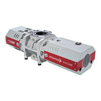
Pfeiffer Vacuum HILOBE 1304 Operating Instructions Manual (136 pages)
Roots pump
Brand:
Pfeiffer Vacuum
| Category:
Water Pump
| Size: 28 MB
Table of Contents
Deutsch
3
Telegram Example
2
Table of Contents
3
Zu dieser Anleitung
8
Gültigkeit
8
Mitgeltende Dokumente
8
Varianten
8
Zielgruppe
8
Konventionen
8
Anweisungen IM Text
8
Piktogramme
9
Aufkleber auf dem Produkt
9
Abkürzungen
11
Sicherheit
12
Allgemeine Sicherheitshinweise
12
Sicherheitshinweise
12
Sicherheitsmaßnahmen
15
Einsatzgrenzen
16
Bestimmungsgemäße Verwendung
17
Vorhersehbarer Fehlgebrauch
17
Personenqualifikation
18
Personenqualifikation Sicherstellen
18
Personenqualifikation bei Wartung und Reparatur
18
Produktbeschreibung
19
Funktion
19
Antrieb
21
Kühlung
21
Einbaulagen
21
Produkt Identifizieren
21
Produktmerkmale
21
Lieferumfang
21
Transport und Lagerung
22
Vakuumpumpe Transportieren
22
Vakuumpumpe Lagern
23
Installation
24
Einbaulagen
24
Vakuumpumpe Aufstellen
25
Schmiermittel Einfüllen
26
Vakuumseite Anschließen
27
Vorvakuumseite Anschließen
28
Schaltkasten Anschließen
29
Temperatursensoren und Lüfter Anschließen
30
Elektrische Schutzmaßnahmen Einrichten
30
Netzanschluss Herstellen
31
Spannungsausgang
33
Schnittstelle "Remote
33
Schnittstellen
33
Eingänge
34
Ausgänge
34
Rs-485
34
Schnittstelle RS-485 Verwenden
35
Pfeiffer Vacuum Protokoll für RS-485-Schnittstelle
36
Telegrammrahmen
36
Telegrammbeschreibung
36
Telegramm Beispiel
36
Telegramm Beispiel
37
Datentypen
37
Parametersatz
38
Allgemeines
38
Stellbefehle
38
Statusabfragen
39
Sollwertvorgaben
40
Zusätzliche Parameter für das Steuergerät
40
Betrieb
41
Vakuumpumpe in Betrieb Nehmen
41
Vakuumpumpe Einschalten
41
Sperrgasmenge Einstellen
42
Anschlüsse mit dem Pfeiffer Vacuum Parametersatz Konfigurieren
42
Betriebsarten
43
Normalbetrieb
44
Stand-By-Betrieb
44
Drehzahlstellbetrieb
44
Betriebsüberwachung
44
Betriebsanzeige über LED
44
Ausschalten und Fluten
45
Schmiermittelstand Kontrollieren
45
Temperaturüberwachung
45
Wartung
47
Wartungsinformationen
47
Checkliste für Inspektion und Wartung
47
Luftfilter Reinigen
49
Schmiermittel Wechseln
49
Schmiermittel Ablassen
50
Schmiermittel Einfüllen
51
Außerbetriebnahme
52
Stillsetzen für Längere Zeit
52
Wiederinbetriebnahme
52
Recycling und Entsorgung
53
Allgemeine Entsorgungshinweise
53
Wälzkolbenpumpe Hilobe Entsorgen
53
Störungen Beheben
54
Allgemeines
54
Störungen
54
Fehlercodes
55
Warn- und Fehlermeldungen bei Betrieb mit Steuergeräten
56
Servicelösungen von Pfeiffer Vacuum
58
Ersatzteilpakete Bestellen
60
Zubehör
61
Zubehörinformationen
61
Zubehör Bestellen
61
Technische Daten und Abmessungen
63
Allgemeines
63
Medienberührende Werkstoffe
63
Technische Daten
64
Abmessungen
65
English
71
About this Manual
76
Applicable Documents
76
Conventions
76
Instructions in the Text
76
Target Group
76
Variants
76
Pictographs
77
Stickers on the Product
77
Fig. 1: Position of Stickers on Product with Vertical Direction of Flow
78
Tbl. 1: Stickers on the Product
78
Abbreviations
79
Fig. 2: Position of Stickers on Product with Horizontal Direction of Flow
79
General Safety Information
80
Safety
80
Safety Instructions
80
Safety Precautions
83
Limits of Use
84
Tbl. 3: Permissible Ambient Conditions
84
Fig. 3: Max. Permissible Pressure Differential between Input and Output Sides, in Ac
85
Foreseeable Improper Use
85
Proper Use
85
Ensuring Personnel Qualification
86
Personnel Qualification
86
Personnel Qualification for Maintenance and Repair
86
Fig. 4: Design, Vertical Direction of Flow
87
Function
87
Product Description
87
Fig. 5: Design, Horizontal Direction of Flow
88
Fig. 6: Design, Switch Box
88
Cooling
89
Drive
89
Identifying Product
89
Mounting Orientations
89
Product Features
89
Scope of Delivery
89
Tbl. 4: Features of the Roots Pumps
89
Transportation and Storage
90
Transporting Vacuum Pump
90
Fig. 7: Transporting Vacuum Pump
91
Storing Vacuum Pump
91
Fig. 8: Mounting Orientation: Vertical Direction of Flow
92
Fig. 9: Mounting Orientation: Horizontal Direction of Flow
92
Installation
92
Mounting Orientations
92
Fig. 10: Minimum Distances
93
Filling with Lubricant
93
Setting up Vacuum Pump
93
Fig. 11: Filling with Lubricant
94
Connecting the Fore-Vacuum Side
95
Connecting the Vacuum Side
95
Connect the Switch Box
96
Connecting Temperature Sensors and Fan
97
Fig. 12: Connect the Switch Box
97
Fig. 13: Connecting Extension Cable
97
Connecting to Mains Power Supply
98
Implement Electrical Safety Measures
98
Fig. 14: Mains Connection Pin Assignment
99
Tbl. 5: Required Properties of the Power Supply Cable
99
Fig. 15: Pin Assignment of the D-Sub Socket, 15-Pin
100
Interfaces
100
Remote" Interface
100
Tbl. 6: Plug Arrangement of the D-Sub Socket, 15-Pin
100
Voltage Output
100
Inputs
101
Outputs
101
Rs-485
101
Using RS-485 Interface
101
Fig. 16: Cross-Link Via Connection RS-485 Using Connection Cables and Accessories
102
Pfeiffer Vacuum Protocol for RS-485 Interface
102
Tbl. 7: Features of the RS-485 Interface
102
Telegram Frame
102
Telegram Description
103
Telegram Example
103
Data Types
104
Control Commands
105
General
105
Parameter Set
105
Tbl. 8: Explanation and Meaning of the Parameters
105
Status Requests
106
Additional Parameters for the Control Unit
107
Reference Value Inputs
107
Commissioning Vacuum Pump
108
Operation
108
Switching on the Vacuum Pump
108
Adjusting Sealing Gas Amount
109
Configuring the Connections with the Pfeiffer Vacuum Parameter Set
109
Normal Operation
110
Operating Modes
110
Tbl. 13: Configuration with Parameters [P:019] and [P:024]
110
Tbl. 14: Configuration with Parameters [P:060] and [P:061]
110
Operating Mode Display Via LED
111
Operation Monitoring
111
Rotation Speed Setting Mode
111
Stand-By Operation
111
Check the Lubricant Level
112
Switching off and Venting
112
Temperature Monitoring
112
Checklist for Inspection and Maintenance
114
Maintenance
114
Maintenance Information
114
Tbl. 16: Maintenance Intervals
115
Changing Lubricant
116
Cleaning Air Filter
116
Fig. 17: Replace the Filter Mat of the Fan
116
Draining Lubricant
117
Fig. 18: Draining Lubricant
117
Fig. 19: Filling with Lubricant
118
Filling with Lubricant
118
Decommissioning
119
Recommissioning
119
Shutting down for Longer Periods
119
Dispose of Hilobe Roots Pumps
120
General Disposal Information
120
Recycling and Disposal
120
General
121
Malfunctions
121
Troubleshooting
121
Error Codes
122
Warning and Malfunction Messages When Operating with Control Units
123
Service Solutions by Pfeiffer Vacuum
124
Ordering Spare Part Packages
126
Tbl. 21: Hilobe Spare Parts Packages
126
Accessories
127
Accessory Information
127
Ordering Accessories
127
Tbl. 22: Accessories
128
Tbl. 23: Consumables
128
General
129
Substances in Contact with the Media
129
Technical Data and Dimensions
129
Technical Data
130
Dimensions
132
Fig. 20: Hilobe 1004, Hilobe 1304, Hilobe 2104 | DN
132
Fig. 21: Electronic Drive Unit RC 5500
133
Advertisement
Pfeiffer Vacuum HILOBE 1304 Operating Instructions Manual (68 pages)
Roots pump
Brand:
Pfeiffer Vacuum
| Category:
Water Pump
| Size: 15 MB
Table of Contents
Table of Contents
3
1 About this Manual
7
Validity
7
Applicable Documents
7
Variants
7
Target Group
7
Conventions
7
Instructions in the Text
7
Pictographs
8
Stickers on the Product
8
Tbl. 1: Stickers on the Product
9
Fig. 1: Position of Stickers on Product with Vertical Direction of Flow
9
Abbreviations
10
Tbl. 2: Abbreviations Used
10
Fig. 2: Position of Stickers on Product with Horizontal Direction of Flow
10
2 Safety
11
General Safety Information
11
Safety Instructions
11
Safety Precautions
14
Limits of Use
15
Tbl. 3: Permissible Ambient Conditions
15
Proper Use
16
Foreseeable Misuse
16
Fig. 3: Max. Permissible Pressure Differential between Input and Output Sides, in Ac
16
Personnel Qualification
17
Ensuring Personnel Qualification
17
Personnel Qualification for Maintenance and Repair
17
3 Product Description
18
Function
18
Fig. 4: Design, Vertical Direction of Flow
18
Fig. 5: Design, Horizontal Direction of Flow
19
Fig. 6: Design, Switch Box
19
Drive
20
Cooling
20
Mounting Orientations
20
Identifying the Product
20
Product Features
20
Scope of Delivery
20
Tbl. 4: Features of the Roots Pumps
20
4 Transportation and Storage
21
Transporting the Vacuum Pump
21
Store the Vacuum Pump
22
Fig. 7: Transporting the Vacuum Pump
22
5 Installation
23
Set up the Vacuum Pump
23
Mounting Orientations
23
Filling with Lubricant
24
Fig. 8: Mounting Orientation: Vertical Direction of Flow
24
Fig. 9: Mounting Orientation: Horizontal Direction of Flow
24
Connecting the Vacuum Side
25
Fig. 10: Filling with Lubricant
25
Connecting the Fore-Vacuum Side
26
Connect the Switch Box
27
Fig. 11: Connect the Switch Box
27
Connect the Temperature Sensors and Fan
28
Implement Electrical Safety Measures
28
Fig. 12: Connect the Extension Cable
28
Connect to Mains Power Supply
29
Fig. 13: Mains Connection Pin Assignment
29
6 Interfaces
31
Remote" Interface
31
Voltage Output
31
Tbl. 6: Plug Arrangement of the D-Sub Socket, 15-Pin
31
Fig. 14: Pin Assignment of the D-Sub Socket, 15-Pin
31
Inputs
32
Outputs
32
Rs-485
32
Interface RS-485
32
Pfeiffer Vacuum Protocol for RS-485 Interface
33
Telegram Frame
33
Tbl. 7: Features of the RS-485 Interface
33
Fig. 15: Cross-Link Via Connection RS-485 Using Connection Cables and Accessories
33
Telegram Description
34
Telegram Example
34
Data Types
35
7 Parameter Set
36
General
36
Control Commands
36
Tbl. 8: Explanation and Meaning of the Parameters
36
Status Requests
37
Reference Value Inputs
38
Additional Parameter for the DCU
38
8 Operation
39
Commissioning the Vacuum Pump
39
Switching on the Vacuum Pump
39
Configuring the Connections with the Pfeiffer Vacuum Parameter Set
39
Operating Modes
40
Tbl. 13: Configuration with Parameters [P:019] and [P:024]
40
Tbl. 14: Configuration with Parameters [P:060] and [P:061]
40
Normal Operation
41
Stand-By Operation
41
Rotation Speed Setting Mode
41
Operation Monitoring
41
Operating Mode Display Via LED
41
Temperature Monitoring
42
Check the Lubricant Level
42
Switching off and Venting
42
Tbl. 15: Meaning of the Leds
42
9 Maintenance
44
Maintenance Information
44
Checklist for Inspection and Maintenance
44
Tbl. 16: Maintenance Intervals
45
Cleaning the Air Filter
46
Changing the Lubricant
46
Fig. 16: Replace the Baffle Strainer of the Fan
46
Draining the Lubricant
47
Filling with Lubricant
47
Fig. 17: Drain the Lubricant
47
Fig. 18: Filling with Lubricant
48
10 Decommissioning
49
Shutting down for Longer Periods
49
Recommissioning
49
11 Recycling and Disposal
50
General Disposal Information
50
Dispose of Hilobe Roots Pumps
50
12 Malfunctions
51
General
51
Troubleshooting
51
Error Codes
52
Warning and Error Messages When Operating with DCU
53
13 Service Solutions by Pfeiffer Vacuum
54
14 Ordering Spare Part Packages
56
Tbl. 21: Hilobe Spare Parts Packages
56
15 Accessories
57
Accessory Information
57
Order Accessories
57
Tbl. 22: Accessories
58
Tbl. 23: Consumables
58
16 Technical Data and Dimensions
59
General
59
Substances in Contact with the Media
59
Technical Data
60
Dimensions
62
Fig. 19: Hilobe 1004, Hilobe 1304, Hilobe 2104 | DN 100
62
Fig. 20: Electronic Drive Unit RC 5500
63
Declaration of Conformity
64
Pfeiffer Vacuum HILOBE 1304 Operating Instructions Manual (64 pages)
Roots pump
Brand:
Pfeiffer Vacuum
| Category:
Water Pump
| Size: 14 MB
Advertisement
Advertisement
Related Products
Pfeiffer Vacuum HILOBE 1302
Pfeiffer Vacuum HILOBE 1302 H
Pfeiffer Vacuum HILOBE 1304 H
Pfeiffer Vacuum HILOBE 1301
Pfeiffer Vacuum HILOBE 1004 H
Pfeiffer Vacuum HIPACE 1200 C
Pfeiffer Vacuum HILOBE 1001
Pfeiffer Vacuum adixen DRYTEL 1025 Series
Pfeiffer Vacuum HIPACE 1500 T
Pfeiffer Vacuum HIPACE 1200 T
Pfeiffer Vacuum Categories
Water Pump
Control Unit
Measuring Instruments
Industrial Equipment
Security Sensors
More Pfeiffer Vacuum Manuals
Login
Sign In
OR
Sign in with Facebook
Sign in with Google
Upload manual
Upload from disk
Upload from URL