Sign In
Upload
Manuals
Brands
Omron Manuals
Network Hardware
SYSMAC CS1W-SCU41-V1
Omron SYSMAC CS1W-SCU41-V1 Manuals
Manuals and User Guides for Omron SYSMAC CS1W-SCU41-V1. We have
1
Omron SYSMAC CS1W-SCU41-V1 manual available for free PDF download: Operation Manual
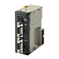
Omron SYSMAC CS1W-SCU41-V1 Operation Manual (781 pages)
SYSMAC CS Series; SYSMAC CJ Series. Serial Communications Boards and Serial Communications Units
Brand:
Omron
| Category:
Network Hardware
| Size: 8.41 MB
Table of Contents
Table of Contents
7
Operation Manual
1
About this Manual
10
Precautions
16
1 Intended Audience
17
2 General Precautions
17
3 Safety Precautions
17
4 Operating Environment Precautions
18
5 Application Precautions
19
6 Conformance to EC Directives
21
Applicable Directives
21
Concepts
21
Conformance to EC Directives
22
EMI Measures for Serial Communications Boards and Units
22
EMS Measures for Serial Communications Units
23
7 Unit Versions of CS/CJ-Series Serial Communications Boards/Units
23
8 Functions Added in the Unit Version 1.3 Upgrade
27
9 Functions Added in the Unit Version 1.2 Upgrade
27
Section 1 Introduction
30
Introduction
30
Using this Manual
31
Overview
32
Serial Communications Boards
32
Serial Communications Units
33
Protocol Overview
36
Host Link Mode
37
Protocol Macros
38
1:N NT Links
39
Loopback Test
40
Serial Gateway Mode
40
No-Protocol Mode
40
Modbus-RTU Slave Mode
41
Features
41
Serial Communications Boards and Units
41
Protocols
41
System Configurations
45
Specifications
52
Serial Communications Boards and Unit
52
General Specifications
54
Protocol Specifications
55
Comparison to Previous Products
64
Selecting the Serial Communications Mode
70
Basic Operating Procedure
71
Overview
71
Explanation of Procedure
72
Section 2 Initial Settings and I\/O Memory Allocations
90
Initial Settings and I/O Memory Allocations
90
Component Names and Functions
91
Serial Communications Boards (CS Series Only)
91
CS-Series Serial Communications Unit
95
CJ-Series Serial Communications Unit
98
Data Exchange with the CPU Unit
101
Serial Communications Board (CS Series Only)
101
Serial Communications Units (CS/CJ Series)
102
I/O Memory Allocations
103
DM Area
103
CIO Area
108
Related Auxiliary Area Bits
114
Section 3 Installation and Wiring
118
Installation and Wiring
118
Installing a Serial Communications Board
119
Precautions in Handling the Board
120
Installing Serial Communications Units
120
System Configuration Precautions
120
CS-Series Serial Communications Unit
121
CJ-Series Serial Communications Unit
122
Unit Handling Precautions
123
Wiring
124
Communications Modes and Ports
124
Port Types
124
Wiring Precautions
124
Connector Pin Layout
125
Mounting Height and Connector Cover Dimensions
126
Reducing Electrical Noise for External Wiring
126
2-Wire and 4-Wire Connections
127
Connections for Host Link Communications
128
NT-AL001-E Link Adapter Settings
128
And Modbus-RTU Slave Mode
135
1:N NT Link Connections with Programmable Terminals
142
Connections in Loopback Test
143
RS-232C and RS-422A/485 Wiring
143
Recommended RS-232C Wiring Examples
143
Recommended RS-422A/485 Wiring Examples
145
Wiring Connectors
147
Soldering
148
Assembling Connector Hood
149
Connecting to Unit
150
Section 4 Using Host Link Communications
152
Using Host Link Communications
152
Host Link Communications
153
Setup Area Allocations
153
Setup Area Words
153
Setup Area Contents
155
Auxiliary Area and CIO Area Allocations
157
Auxiliary Area Allocations
157
CIO Area Allocations
158
Communications Timing
161
Simultaneous Commands and Communications Ports
161
Communications Control Signals and Communications Timing
162
Flags for Network Communications
162
Timing of Commands Addressed to a Host Computer
163
Error Responses
165
Reception Buffers
165
Changes from Previous Products
165
RS-232C Ports
166
RS-422A/485 Ports
167
Host Link Function for Replacing Existing Plcs
168
Support for 1:1 Host Link
168
Host Link-Compatible Device Selection
170
Section 5 Using Protocol Macros
174
Using Protocol Macros
174
Overview of the Protocol Macro Functions
175
Protocol Macro Functions
175
Using the Protocol Macro Function
175
Protocol Structure
177
Setup Area Allocations
182
Setup Area Words
182
Setup Area Allocations
183
Auxiliary Area and CIO Area Allocations
188
Auxiliary Area Allocations
188
CIO Area Allocations
190
Software Switches
191
Status Area
193
Using Protocol Macros
205
Executing Communications Sequences
205
Ladder Program Structure
209
Ladder Program Example
210
Simple Backup Function (Backup of Protocol Macro Data)
216
Enhanced Protocol Macro Functions
219
Data Exchange Timing for Link Words
220
Clearing/Holding Contents of Reception Buffer in Full-Duplex Mode
222
High-Speed Baud Rate for Protocol Macro Mode
222
Section 6 Serial Gateway
224
Serial Gateway
224
Serial Gateway Overview
225
Features
225
Operating Conditions
225
Overview
225
Serial Gateway Specifications
229
DM Area Allocations (Using Serial Gateway Mode)
230
Auxiliary Area and CIO Area in Serial Gateway Mode
233
Using the Serial Gateway
237
Protocol Conversion
241
Converting FINS to Compoway/F
241
Types of Protocol Conversion
241
Compoway/F Connection Examples
245
Converting FINS to Modbus-RTU
246
Converting from FINS to Modbus-ASCII
249
Converting from FINS to Host Link FINS
250
Serial Gateway
255
Serial Gateway Execution Timing for Protocol Macros
255
Serial Gateway Timeout Monitoring
257
Other Functions
259
Conditions Requiring Routing Tables
259
Treating Serial Communications Paths as Networks
259
Using a PLC as the Target
260
Using a Non-PLC Component as the Target
262
Explanation
264
Communications Frames
266
Compoway/F
266
Modbus-RTU
267
Modbus-ASCII
268
Host Link FINS
269
Sending Commands Using the CMND(490) Instruction
270
Section 7 No-Protocol Mode
278
Overview
279
Definition
279
Specifications
280
Allocation DM Area for No-Protocol Mode
281
Auxiliary Area and CIO Area Allocations
283
Basic Operating Procedure in No-Protocol Mode
289
Procedure Using No-Protocol Mode
289
Connections (No-Protocol Mode)
289
Using 1:N NT Links
292
Overview of 1:N NT Links
293
Setup Area Allocations
295
Auxiliary Area and CIO Area Allocations
296
Section 9 Using Modbus-Rtu Slave Mode (Unit Version 1.3 or Later)
302
Modbus-RTU Slave System
303
Communicating with CS/CJ-Series CPU Units Using Modbus
303
Setup Area Allocations (Modbus-RTU Slave Mode)
304
Setup Area Words
304
Setup Area Contents
306
Auxiliary Area and CIO Area Allocations (Modbus-RTU Slave Mode)
307
Auxiliary Area Allocations
307
CIO Area Allocations
308
Supported Modbus-RTU Commands
312
Command and Response Details
312
Communications Timing
319
Simultaneous Commands and Communications Ports
319
Communications Control Signals and Communications Timing
320
Flags for Network Communications
320
Timing of Commands Addressed to a Host Computer
322
Reception Buffers
324
Error Responses
324
Changes from Previous Products
324
RS-232C Ports
324
RS-422A/485 Ports
326
Modbus-RTU Slave Function for Replacing Existing Plcs
327
Support for 1:1 Modbus-RTU Slave
327
Modbus-RTU Slave-Compatible Device Selection
328
Loopback Test
332
Executing Loopback Tests
333
Setup Area Allocations
334
CIO Area Allocations
335
Section 11 Troubleshooting and Maintenance
336
Troubleshooting and Maintenance
336
Serial Communications Unit
337
Indicator Error Displays
337
Serial Communications Boards (CS Series Only)
337
Serial Communications Units (CS/CJ Series)
339
Status Area Error Indications
340
Troubleshooting
341
Host Link Communications
341
Serial Gateway (Serial Gateway or Protocol Macro Mode)
347
No-Protocol Mode
354
1:N NT Link Mode
364
Protocol Macros
366
Modbus-RTU Slave Mode
373
Error Logs
376
Error Log Specifications
376
Error Log Table
376
Error Codes and Details
377
Error Log Table Configuration
377
Error Codes and Troubleshooting
379
Controller Data Read: 05 01
380
Reading and Clearing Error Log Tables
380
Error Log Read: 21 02
381
Error Log Clear: 21 023
382
Cleaning and Inspection
383
Cleaning
383
Inspection
383
Replacement Precautions
384
Precautions When Replacing Board or Unit
384
Replacing the Board or Unit
384
Settings after Replacing Board or Unit
384
A Introduction
388
B Compoway/F Master Protocol
392
Appendix B Compoway/F Master Protocol Example: Variable Area Read
396
First Read Address
411
Variable Type
411
Appendix B Variable Type "C0
415
Number of Elements: 4 Digits Hex
415
Read Data
415
Number of Elements "0001
416
Controller Status Read
418
Response Code
419
Bytes
422
D Host Link FINS Command Master
446
E Mitsubishi Computer Link Master (A-Compatible 1C Frame, Model 1)
470
Connection Configuration
495
I E5ZE Temperature Controller Write Protocol
571
K ES100@ Digital Controller Protocol
588
System Setting
652
M V500/V520 Bar Code Reader Protocol
661
N 3Z4L Laser Micrometer Protocol
662
O Visual Inspection System Protocol
698
P V600/V620 ID Controller Protocol
718
Modem Settings
758
Communication Errors
762
R Changing Communications Port Settings Using STUP(237)
767
Index
768
Revision History
778
Advertisement
Advertisement
Related Products
OMRON CS1W-SLK11-21 - 06-2004
Omron SYSMAC CS1W-SCB21-V1
Omron SYSMAC CS1W-SCB41-V1
Omron SYSMAC CS1W-SCU21-V1
Omron SYSMAC CS1W-SCU31-V1
Omron SYSMAC CS1W-SLK11
Omron SYSMAC CS1W-SLK21
OMRON CS1W-EIP21 - 10-2010
OMRON CS1W-ETN21 - 04-2009
Omron CS1W-EIP21 - REV 02-2010
Omron Categories
Blood Pressure Monitor
Controller
Accessories
Switch
Inverter
More Omron Manuals
Login
Sign In
OR
Sign in with Facebook
Sign in with Google
Upload manual
Upload from disk
Upload from URL