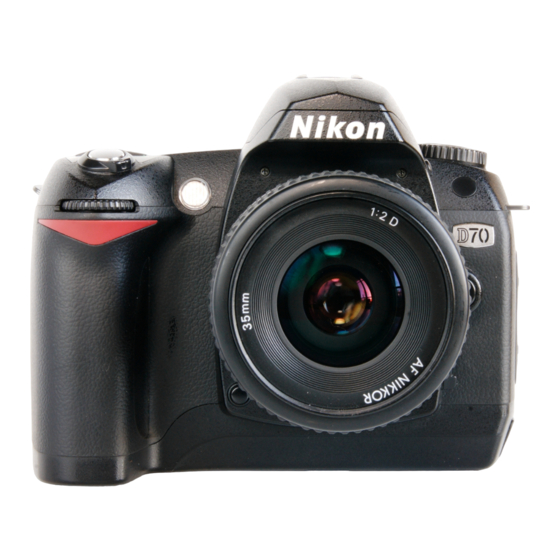
Sign In
Upload
Manuals
Brands
Nikon Manuals
Digital Camera
D70 VBA10401
Nikon D70 VBA10401 Manuals
Manuals and User Guides for Nikon D70 VBA10401. We have
1
Nikon D70 VBA10401 manual available for free PDF download: Repair Manual
Nikon D70 VBA10401 Repair Manual (93 pages)
Brand:
Nikon
| Category:
Digital Camera
| Size: 12.9 MB
Table of Contents
Specifications
2
Disassembly
6
Separate Front and Rear Bodies
6
Discharge Main Condenser
7
Disassemble Rear Cover
8
Memory Compression PCB
9
CCD-PCB Unit
9
DC/DC Pcb
10
Covers
11
SB Pop-Up
11
Top Cover
12
External LCD Unit
12
Disassembly of Top Cover Unit
13
SB Upper Case
13
Lighting Unit PCB
13
Remove Lighting Unit Control PCB, Connection FPC, and Shield Wires
14
SB Lower Case Unit
14
Remove Wire-Holding Screw/Unsolder Wires
14
Remove Flash-Up Spring
15
Remove SB Lower Case Unit
15
Mode Dial PCB Unit, Remote Control Unit, Top Cover FPC
16
Remove Attaching Screws, Soldering Bridges
16
Detach Mode Dial PCB and Remote Control Unit from Top Cover FPC
16
Mode Dial Unit, Release Button, Power-Supply Dial, Other Small Parts
17
Accessory Shoe, Shoe Mold Unit, Outer LCD Window, Other Small Parts
17
Preview SW Unit
18
Front Body
19
Eyepiece Unit
19
Metering FPC Unit
19
Penta Unit
20
Main PCB
21
AF Sensor Unit
22
Shutter Unit
22
Inner LCD Unit
23
Front Body FPC
23
Aperture Control Unit
24
AF Driving Unit
25
Bayonet Unit
25
A/M-Change SW Unit
25
Aperture Lever Unit
26
F-Min Switch Unit
26
Preview Locking Lever Unit
26
Mirror Unit
26
Rear Body
27
If-Pcb
27
Bottom Base Unit
27
Secondary Battery Unit
27
Cf-Pcb
28
Main Condenser
28
Main-SW FPC
29
SB-Pcb/Sub-PCB
29
Separate SB-PCB from Sub-PCB
30
SQ Unit
30
Main-/Sub- Command Dial Unit
31
Rear Body Small Parts
31
Assembly/Adjustment
32
Front Body Assembly
32
Height Adjustment of AF Coupling Shaft
38
Height Adjustment of Aperture Lever
38
Angle Adjustment of Main Mirror and Sub-Mirror
44
Rear Body Assembly
46
Mount Front Body on Rear Body
53
Preview SW Adjustment
53
Inspection and Adjustment of Body Back
54
Inspection and Adjustment of AE CCD Alignment
57
Assembly of Top Cover Unit
58
Accuracy Inspection and Adjustment (Camera Body)
66
How to Connect Communications Tool (J61205)
67
Inspection and Adjustment Software
68
Start-Up of Program
70
AE Inspection and Adjustment
71
AF Inspection and Adjustment
71
Tools Required
71
Infinity Alignment & Adjustment
74
Other Tapes/ Sponges
75
Necessary Adjustments on PC When Parts Are Replaced
77
Adjustment Software
77
Shooting Image Adjustment Software
78
Shooting Image Adjustment
79
The Summary on each Adjustment
82
Sensitivity Adjustment
82
Sensitivity Ratio Adjustment
82
"Sensitivity" and "Sensitivity Ratio" Reference Values Calculation
82
CCD-PCB EEPROM Flashram up
83
TFT PCB EEPROM Flashram up
83
Pixel Defect (Black Spots) Compensation
85
Pixel Defect (White Spots) Compensation
85
Sensitivity Ratio Reference Value Calculation
86
"TFT View Angle" Adjustment (Only for NTSC; Unnecessary for PAL)
86
TFT-PCB EEPROM Flashram up
87
Reading of RISC Version
87
Procedure for Upgrading RISC Firmware
87
Wiring Diagram
88
Tools List
89
Advertisement
Advertisement
Related Products
Nikon D7000
Nikon D70
Nikon D70s
Nikon D700
Nikon D70 - D70 Digital Camera
Nikon D70-series
Nikon D7100
Nikon D7200
Nikon D720
Nikon D780
Nikon Categories
Digital Camera
Camera Lens
Camera Accessories
Microscope
Measuring Instruments
More Nikon Manuals
Login
Sign In
OR
Sign in with Facebook
Sign in with Google
Upload manual
Upload from disk
Upload from URL