Sign In
Upload
Manuals
Brands
Mitsubishi Electric Manuals
Recording Equipment
M800V Series
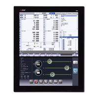
Mitsubishi Electric M800V Series Manuals
Manuals and User Guides for Mitsubishi Electric M800V Series. We have
3
Mitsubishi Electric M800V Series manuals available for free PDF download: Instruction Manual, Manual, Maintenance Manual
Mitsubishi Electric M800V Series Instruction Manual (896 pages)
Numerical Control (CNC)
Brand:
Mitsubishi Electric
| Category:
Control Systems
| Size: 16 MB
Table of Contents
Supported Models
2
Abbreviations in this Manual
2
Manual List
3
Precautions for Safety
7
Treatment of Waste
13
Table of Contents
17
Outline of Display Unit and Screens
26
Display Unit and Keyboard Unit
27
External Memory Interface
30
Standard Screen and Home Screen
31
Change Screen Buttons and Menu Buttons
33
Change Screen Buttons
33
Menu Operations
34
Menu List View Function
35
Main Menu List
37
Main Menu Functions
38
Screen Operations
46
2Screen Operations
47
Standard Screen
47
Screen Configuration
47
Displayed Part System
50
NC Status
51
Operation Mode/MDI Status
52
Operation Status
52
Alarms/Warnings
53
Operation Messages
53
Changing the Screen Theme Color
53
Home Screen
54
Screen Configuration
54
Switching Displayed Part System from the Operation Menu
59
Operating the Application
59
Displaying the Manuals [M800VW Windows-Based Display Unit/M80Vw Windows-Based Display Unit]
61
Home Applications (19-Type Vertical Display Unit)
66
Home Screen (Machine Status Display)
66
Keyboard Application
68
Operation Panel Application
69
Manual Application
70
Note Application
73
Setting Data
75
Setting Numerals and Alphabetical Characters
75
Inputting Operations
76
Guidance Function
78
Parameter Guidance
78
Alarm Guidance
80
G Code Guidance
82
Touchscreen Functions
85
Basic Operation
85
Software Keyboard
87
Touchscreen Operation Functions
92
Changing the Menu Display
93
Displaying the Menu Selection List
93
Scrolling the Displayed Data
94
Changing a Page
95
Switching to the Next Axis or Part System
96
Selecting a File
96
Displaying Edit Window/Selective Display Window
97
Moving a Window
98
Changing the Font Size
99
Displaying the Parameter Guidance
100
Displaying the Alarm Guidance
100
Enlarging or Reducing, Moving, and Rotating a 3D Check Shape
101
Displaying the Screen List
103
Menu Customization Function
104
Changing the Operation Level (Protect Setting Screen)
106
Assigning Arbitrary Character String to a User-Defined Key
107
Format of Configuration File
108
Definition Types of User-Defined Keys
109
Type 1
109
Type 2
111
Editing a Configuration File
113
Outputting the Screen Information (Screenshot Capture Function) [M800VS/M80V Series]
114
Inputting a Machining Program and Defining Variables
116
Inputting a Machining Program
117
Creating and Editing a Machining Program
117
Registering and Editing the MDI Program
130
Registering and Editing the Fixed Cycle Program
132
Fixed Cycle Operation Parameters
132
Transmitting and Erasing the Fixed Cycle Program
132
Erasing a File
133
Editing Operations
135
Changing the Display
135
Displaying an Arbitrary Line
138
Rewriting Data
138
Inserting Data (Initial Data Overwrite Mode)
139
Overwriting Data (Initial Data Insertion Mode)
140
Deleting Data
140
Searching for Character Strings
142
Replacing Character Strings
146
Copying and Pasting Data
147
Undoing Program Changes
149
Searching T Codes
150
Searching a Program from Edit Screen
151
Program Editing Support Function
153
Displaying Input Mistakes
153
Performing Operation Search at the Cursor Position
158
Adding Sequence No. (N No.) Automatically
160
G Code Guidance
161
Playback Editing
162
Displaying the Finished Shape
166
Editing a Multi-Part System Program
167
Multi-Part System Simultaneous Program Editing
167
Special Program Editing Display for Synchronization between Part Systems
174
Inserting Cycle Interactively
176
Types of Cycle
177
Name of Data
179
Screen Configuration
180
Operation Descriptions
181
Operation Procedure
183
Highlighting the Cycle Program
184
Setting Machining Conditions for Vibration Cutting Control
185
Screen Configuration
185
Operation Method
188
Process Analysis Function
191
Screen Configuration
192
Operation Method
195
Defining Variables
197
Common Variables
197
Local Variables
203
Checking a Machining Program on Screen
206
Graphic Check (2D)
207
Checking Continuously
214
Checking One Block at a Time
217
Setting the Coordinate System to Draw
218
Drawing During a Program Check
221
Changing the Display Range
221
Changing the Display Mode
223
Changing the Display Angle
225
Switching the Axis Movement Direction (+/-)
226
Displaying the Machining Program on Checking
227
Switching to Full-Screen Display Mode
227
Setting Auto Graphic
228
Switching the Draw Path
230
Drawing a Path Corresponding to the Rotary Axis (L System)
231
Associating Graphic Check Images with a Machining Program
232
Setting the Drawing Speed of Program Check
233
Availability of Check Mode with Other Functions
234
Handling of Variable Commands, Programmable Parameter Input, and Programmable Compensation Data Input
236
Notes for Graphic Check (2D)
237
Graphic Check (3D) (M System)
242
Switching Check Method
249
Checking Continuously
249
Checking One Block at a Time
252
Checking Multiple Part Systems Simultaneously
253
Canceling the Program Check
254
Enlarging and Reducing the Workpiece Shape
254
Moving the Workpiece Shape
254
Rotating the Workpiece Shape
255
Performing an Interference Check
255
Setting the Workpiece Shape
256
Setting the Tool Shape
262
Associating Graphic Check Images with a Machining Program
262
Setting the Drawing Speed of Program Check
262
Drawing Travel Command of the Rotary Axis
263
Availability of Check Mode with Other Functions
266
Handling of Variable Commands, Programmable Parameter Input, and Programmable Compensation Data Input
269
Notes for Graphic Check (3D)
270
Graphic Check (3D) (L System)
277
Switching Check Method
285
Checking Continuously
285
Checking One Block at a Time
285
Checking Multiple Part Systems Simultaneously
285
Canceling the Program Check
285
Enlarging and Reducing the Workpiece Shape
285
Moving the Workpiece Shape
285
Rotating the Workpiece Shape
285
Performing an Interference Check
286
Setting the Workpiece Shape
287
Setting the Tool Shape
291
Checking a Machining Program between Part Systems
291
Associating Graphic Check Images with a Machining Program
292
Setting the Drawing Speed of Program Check
292
Availability of Check Mode with Other Functions
293
Handling of Variable Commands, Programmable Parameter Input, and Programmable Compensation Data Input
294
Notes for Graphic Check (3D)
294
Machining Simulation (M System) [M800VW Series]
300
Switching Check Method
305
Checking Continuously
305
Checking Block by Block
305
Checking Multiple Part Systems Simultaneously
305
Canceling the Program Check
305
Enlarging/Reducing the Workpiece Shape
305
Moving the Workpiece Shape
305
Rotating the Workpiece Shape
305
Performing an Interference Check
306
Setting the Workpiece Shape
307
Setting the Tool Shape
307
Associating Graphic Check Images with a Machining Program
307
Switching Simulation Modes
308
Availability of Check Mode with Other Functions
309
Handling of Variable Commands, Programmable Parameter Input, and Programmable Compensation Data Input
311
Precautions for 3D Machining Simulation
311
Checking the Tool Command (T Code List)
317
Searching T List
318
Inputting and Outputting a Machining Program
322
Inputting and Outputting a Program
323
Selecting a Device, Directory and File
329
Transferring a File
334
Comparing Files (Compare)
337
Erasing a File
338
Changing a File Name (Rename)
339
Creating a Directory
340
Other Functions
341
Merging a File
341
List of File Names
342
Edit Lock B and C
342
Operation
342
Program Display Lock
343
Data Protection Keys
344
Leading Zero
344
The Batch Input/Output the Machining Program of NC Memory/Nc Memory 2
347
Formatting Memory Card/Ds/Usb Memory
351
Setting a Tool and a Workpiece
352
Setting a Tool
353
Registering a Tool (Tool Registration Screen)
353
Registering a Tool in the Magazine Pot
356
Setting the PLC Command
356
Setting and Erasing the Tool No. of Spindle/Standby Tools
357
Erasing the Tool Registration Data
357
Measuring a Tool (Tool Measurement Screen)
358
Tool Measurement (M System)
358
Tool Measurement (L System)
363
Setting Tool Compensation Amount (Tool Offset Screen)
378
Display Position
383
Setting the Tool Compensation Data
385
Switching the Input Method for the Tool Compensation Data
388
Erasing the Tool Compensation Data
388
Copying and Pasting the Tool Compensation Data
389
Undoing Change of Tool Compensation Data
389
Disabling the Setting of Tool Compensation Amount
390
Measuring Tool Compensation Amount
391
Moving to Designated Compensation Number
400
Setting the Tool Management Data (Tool Management Screen)
401
List of Display Items
403
Data Setting Range
410
Menu Configuration
417
Registering New Tool Management Data
423
Switching the Item Type of the Tool Management Data Detailed Portion
423
Displaying Data by Designating Tool Management Data no
424
Displaying Data by Designating Tool no
425
Sorting the Data by Tool no
426
Deleting the Tool Management Data
427
Copying and Pasting the Tool Management Data
428
Specifying Display Format and Setting Range of Additional Information
431
Tool Life Management
433
Tool Life Management (M System)
434
Registering Tool Life Management Data on the Group Unit Display Screen
435
Operation Descriptions (Tool Life Management I/Lli)
442
Operation Descriptions (Tool Life Management Ll)
442
Registering the Tool Life Management Data Groups on the Group List Display Screen (Tool Life Management I/II)
444
Tool Life Management (L System)
446
Registering the Tool Life Management Data (Tool Life Management I)
447
Registering Tool Life Management Data on the Group Unit Display Screen (Tool Life Management II)
449
Operation Descriptions (Tool Life Management I)
453
Operation Descriptions (Tool Life Management Ll)
454
Registering the Tool Life Management Data Groups on the Group List Display Screen (Tool Life Management II)
456
Tool Life Prediction Function
457
Tool Life Management Set Allocation to Part Systems
458
Setting and Measuring a Workpiece
459
Workpiece Measurement (M System)
459
Carrying out Surface Measurement
462
Carrying out Hole Measurement
464
Carrying out Width Measurement
465
Carrying out Rotation Measurement
467
Performing Automatic Recontact When Contacting the Workpiece
470
Workpiece Measurement (L System)
471
Measuring Instrument I/F Function
477
Setting Workpiece Coordinate System Offset
478
Setting the Coordinate System Offset Amount
481
Erasing the Coordinate System Offset Amount
482
Setting the Workpiece Coordinate Origin
482
Changing the Coordinate System Display
484
Changing the Input Menus to Display
484
Setting the Offset Amount of Workpiece Installation Error
485
Setting the Offset Amount of Workpiece Position for Rotary Axis
488
Setting Workpiece Coordinate System Shift (L System)
490
Manually Setting the Workpiece Coordinate System Shift Value
494
Automatically Setting the Workpiece Coordinate System Shift Value
497
Measuring the Workpiece Installation Error Data
499
Screen Configuration
506
Setting the Measurement Condition
507
Performing Workpiece Installation Error Measurement
509
Precautions for Workpiece Installation Error Measurement
510
Designating the Input Range (Range Setting Screen)
513
Designating the Input Range of the Tool Compensation Amount
514
Designating the Input Range of the Workpiece Coordinate System Offset Amount
516
Designating the Input Range of the Workpiece Coordinate System Shift Amount
518
Setting Parameters
520
Setting User Parameters
521
Selecting the Parameter Number
524
Setting the Parameters
525
Copying and Pasting Parameters
526
Undoing the Parameter Change
527
Parameter Configuration
528
Echoback
528
Ethernet Parameter
528
Setting VNC Server Connection Password
528
Precautions
528
Selecting High-Accuracy Control Parameters (Machining Cond I Screen)
529
Adjusting High-Accuracy Control Parameters
535
Setting Machine Movable Area
540
Setting the Stored Stroke Limit
541
Stored Stroke Limit II
543
Chuck Barrier/Tailstock Barrier (L System)
545
Other Setups
550
Pallet Program Registration
551
Standard Pallet Registration
552
Pallet List Screen
555
Pallet Details Screen
557
R-Navi
560
Selecting Where to Register a Machining Surface (Machining Surface List Screen)
561
Selecting Where to Register a Machining Surface
563
Changing the Surface Name
563
Switching the Workpiece
564
Selecting the Basic Coordinate System
564
Automatically Registering Top and Side Faces as Machining Surfaces
565
Switching the Coordinate System Direction of a Workpiece Graphic
567
Registering and Setting the Workpiece (on the Work Setting Screen)
568
Registering the Workpiece
570
Changing the Workpiece Name
572
Changing the Form of the Work
572
Changing the Workpiece Size
573
Setting the Details of the Surface (on the Surface Detail Screen)
574
Moving the Cursor
577
Setting the Surface Coordinate Origin (Feature Coordinate Origin)
577
Specifying the Surface Coordinate Axial Directions
578
Checking the Setting Value of Coordinate Axis
583
Changing the Combination of Axial Direction
583
Switching the Surface
583
Rotating the Axial Direction of Coordinate Axis
584
Default Settings of Designation Method and Axis Combination
585
Operation
585
Surface Selection
586
Selecting a Machining Target Surface
588
Indexing the Machining Target Surface
589
Canceling the Machining Target Surface
590
Switching the Machining Target Surface
591
Switching the Workpiece
591
Integrated Time
592
Integrated Time Display
592
Setting the Integrated Time
593
Setting the Time Display Selection
594
Counter Setting
595
Origin Set, Origin Cancel
597
Manual Numerical Value Command
599
MDI Program Editing
601
PLC Switch
603
Turning PLC Switches ON/OFF
604
Thread Recutting Function
605
Storing the Thread Groove Position
606
Switching the Stored Thread Groove ON/OFF
607
Erasing the Stored Thread Groove Position
607
Email Notification Function to Operator
608
Setting for Email Transmission Environment
609
Email Transmission Test
614
Description of Email Transmission Function
615
Inputting and Outputting Data
615
Checking the Settings Change History
617
Changing the Data Type Displayed in the Settings Change History
621
Undoing Changes
621
Displaying the Parameter Guidance
621
Machining a Workpiece
622
Operation Search
623
Executing an Operation Search
628
Changing Whether to Show or Hide the Comment Field
631
Changing the Sorting Method
632
Checking the Movement under Machining (Monitor Screen)
633
Screen Layout
633
Switching the Display Format
648
Switching the Counter Types
649
Switching the Spindle No. to be Displayed on Counter
652
Operation of 2-Part/3-Part/4-Part System Simultaneous Display
652
Counter All-Axis Display
654
Modal Display
656
Program Tree Display
661
Integrated Time Display
662
Load Meter Display
663
Spindle, Standby Display
665
Tool Center Coordinate Display
667
All Spindles' Rotation Speed Display
669
Checking the Movement under Machining (Trace Screen)
670
Displaying the Trace
674
Displaying the Machine Position of the Tool Center Point Trace
675
Changing the Display Range
675
Changing the Display Mode
677
Changing the Display Angle
678
Displaying the Machining Program on Checking
679
Switching the Full-Screen Display Mode
679
Switching the Axis Movement Direction (+/-)
679
Drawing a Path Corresponding to the Rotary Axis
679
Precautions for Tracing
679
Machine Interference Check (M System) [M800VW/M80VW Series]
680
Monitor Screen (Main Screen)
683
Registering a Tool Model
684
Setting the Shape Data (Jig/Workpiece)
685
Arranging the Shape Data
688
Entering an Inclination Angle (Block)
688
Measuring a Reference Point of Shape
689
Setting the Shape Group as the Interference Check Target
693
Positioning the Shape Part
694
Setting Whether to Show/Hide the Components
696
Parts Selection Screen
696
Display Setting Screen
697
Inputting/Outputting the Shape Group Data
698
Machining the Workpiece During Interference Check
700
Manual Operation
700
Automatic Operation
700
Canceling the Machine Interference Alarm
701
Disabling the Interference Check
701
Real-Time 3D Machine Interference Check (M System) [M800VW Series]
701
Restart Search
702
Main Screen
706
Top Search Screen
708
File Setting Screen
709
MSTB History Screen
710
Operation Sequence for Program Restart
711
Executing Restart Search (Restart Type 1)
714
Executing Restart Search (Restart Type 2)
715
Executing Restart Search (Restart Search for All Part Systems in Batch)
718
Returning to the Restart Position
719
Executing the MSTB Commands
721
Collation and Stop
722
Correcting the Machining Program
726
Program Editing
726
Buffer Correction
732
Chatter Suppression
736
Adjusting the Variation Conditions
737
Troubleshooting
740
11Troubleshooting
741
Confirming the NC Message (Alarm Screen)
741
Alarm History
743
Checking Machine Status
745
System Configuration Screen
745
Option Display Screen
748
Drive Monitor Screen (Servo Unit)
749
Drive Monitor Screen (Spindle Unit)
754
Drive Monitor Screen (Power Supply Unit)
759
Drive Monitor Screen (Synchronous Error)
761
Clearing the Alarm History on Drive Monitor Screen
762
Diagnosis Screens
763
Self Diagnosis Screen
763
Servo Diagnosis Screen
768
Collecting the Data on the Diagnosis Data Collection Setting Screen
771
Advanced Diagnosis
774
Displaying and Setting the PLC Device Data (I/F Diagnosis Screen)
774
Displaying the PLC Device Data
776
Carrying out Modal Output
777
Carrying out One-Shot Output
778
Writing and Reading the Data Using the NC Data Designation (NC Memory Diagnosis Screen)
779
Collecting the NC Data (Data Sampling Screen)
781
Safety Observation
782
Safety Observation Screen (Configuration Diagnosis)
782
Safety Observation Screen (Signal Monitor)
784
Safety Observation Screen (Drive Monitor)
786
Safety Observation Screen (Version Display)
789
Performing a Backup Operation
790
Selecting a Device, Directory and File
795
Transferring a File
803
Comparing Files (Compare)
807
Erasing a File
808
Changing a File Name (Rename)
809
Creating a Directory
810
Restrictions
811
Device Definition
811
List Display
811
Other Functions
813
Merging a File
813
List of File Names
814
Edit Lock B and C
816
Data Protection Keys
817
The Batch Input/Output the Machining Program of NC Memory
817
Format Memory Card/Ds/Usb Memory
821
Performing Batch Backups of NC Memory Data
822
All Backup
825
All Restoration
827
Daily Maintenance
830
Appendix 1: Rotation Center Error Measurement Function (M System)
834
Screen Configuration
837
Measuring the Rotation Center Error Data
839
Appendix 2: Wireless LAN Function [M800VS/M80V Series]
842
Appendix 2: Wireless LAN Function
842
Configuring the Wireless LAN
845
Configuring for Access Point (AP) Mode
845
Verifying Connection
845
Configuring for Station (STA) Mode
847
Wireless LAN Diagnosis Screen
849
Setting the Access Point (AP) Nearby as Connection Destination
852
Description of Advanced Functions
853
Dhcp
853
ESSID Stealth
856
AP Isolation
856
Abg Mode
856
Bssid
856
Relationship with Other Functions
857
Troubleshooting
858
The Software License Authorized for this Function
859
Appendix 3: IP Filter Setting Function
860
Setting the IP Address Filter
861
Examples for Using IP Address Filter
863
Appendix 4: VNC Server Function
866
Environment Establishment (Preparation)
867
Displaying the NC Screen with VNC Client
868
Connecting VNC Client
868
Operating the NC Using the Keyboard
870
Imposing Restrictions to VNC Client Operations
870
Troubleshooting
871
Appendix 5: Web Access (NC Screen Remote Browsing) [M800VS/M80V Series]
874
Setting for Web Access
876
Setting Parameters
876
Setting the IP Address
876
Displaying the CNC Screen on Web Browser
877
Explanations of the Screens
878
Operation Method
879
Appendix 6: List of Function Codes
880
Appendix 7: RS-232C I/O Device Parameter Setting Examples
882
Appendix 7: RS-232C I/O Device
882
Appendix 8: Other Functions for Reference
884
F1-Digit Feed
885
Global Service Network
893
Advertisement
Mitsubishi Electric M800V Series Manual (788 pages)
Brand:
Mitsubishi Electric
| Category:
Recording Equipment
| Size: 5 MB
Table of Contents
Table of Contents
13
1 List of Devices
14
List of Devices
15
Device Range Setting at Multi-Project
16
File Register General Map
18
2 Input/Output Signals with Controller
20
PLC Input Signals (Bit Type: X***)
23
PLC Input Signals (Data Type: R***)
49
PLC Output Signals (Bit Type: Y***)
87
PLC Output Signals (Data Type: R***)
114
Special Relay/Special Register
142
ZR Devices
144
Classified for each Application
154
3 Other Devices
172
4 Explanation of Interface Signals
176
PLC Input Signals (Bit Type: X***)
178
PLC Input Signals (Data Type: R***)
291
PLC Output Signals (Bit Type: Y***)
370
PLC Output Signals (Data Type: R***)
539
Explanation of Special Relays (SM***)
641
Explanation of ZR Device
642
Smart Safety Observation
642
Plc -> Cnc
642
Cnc -> Plc
660
Memory Switch (PLC Switch)
685
MES Interface Library
686
Diagnosis Data Output
700
Spindle Protection
703
External Encoder Position Output I/F
704
Machine Contact Input/Output I/F
705
Biss Encoder I/F
708
5 Appx.1: PLC Window
710
Details
711
Read/Write Operation
713
PLC Window Interface
715
Parameter Interface
715
Read Window Interface
717
Write Window Interface
718
Read Window Expanded Interface
719
Write Window Expanded Interface
720
Interface for Consecutive Writes Detection Log
721
Data Type
722
Read/Write PLC Axis Data
723
Precautions
724
Usage Example
725
6 Appx.2: List of PLC Window Data
728
Section No. List
729
Sub-Section No. List
731
7 Appx.3: List of Option Status Exported to PLC
762
Mitsubishi Electric M800V Series Maintenance Manual (226 pages)
Numerical Control
Brand:
Mitsubishi Electric
| Category:
Control Systems
| Size: 15 MB
Table of Contents
Supported Models
2
Manual List
3
Precautions for Safety
7
Treatment of Waste
16
Table of Contents
20
System Basic Configuration
24
1System Basic Configuration
25
System Basic Configuration Drawing
25
General Connection Diagram
27
M800VW Series, Windows-Based Display Unit
28
M80VW Series, Windows-Based Display Unit
29
M800VS Series
30
M80V Series
31
19-Type Display Unit (M800VW/M80VW Series, Windows-Based Display Unit)
32
19-Type Display Unit (M800VS/M80V Series)
33
Connecting an Operation Panel I/O Unit (FCU8-DX834) (M800VS/M80V Series)
34
Connecting a Pulse-Controlled Inverter (M80V Series)
35
Connecting an Image Input Expansion Unit (M800VS/M80V Series)
36
Connecting a Laser I/F Unit (M800VW/M80VW Series)
37
Connecting a Laser I/F Unit (M800VS/M80V Series)
38
Connecting a Biss Encoder (M800VS/M80V Series)
39
Connecting an Ecomonitorlight (M800VS/M80V Series)
39
How to Check the System Configuration
40
System Configuration Screen
40
Option Display Screen
43
Each Unit Status Display
44
Control Unit
44
Personal Computer Unit
48
Operation Panel I/O Unit
49
Remote I/O Unit
52
Laser I/F Unit
54
Function Expansion Unit
55
CC-Link Expansion Unit
55
CC-Link IE TSN Expansion Unit
56
PROFIBUS-DP Master Unit
57
CC-Link IE Field
58
Ethernet/Ip
59
FL-Net
60
7-Segment Leds on the Control Unit
61
Normal State Display
61
Error Display at NC Startup
61
Display When an Alarm Occurs
62
Daily Maintenance and Periodic Maintenance
72
Daily Maintenance
74
Touchscreen
74
Escutcheon
74
Periodic Maintenance
75
List of Durable Parts
75
List of Replacing Parts
75
Durable Parts Replacement
76
Control Unit Battery
76
Replacement Procedures
76
Personal Computer Unit Battery [M800VW/M80VW]
78
Personal Computer Unit Cooling Fan [M800VW/M80VW]
79
Replacing Fuse
80
Maintenance of the Drive Unit
84
Periodic Inspections
85
Durable Parts
86
Adding and Replacing Units and Parts
87
MDS-E/EH Series
87
Replacing the Drive Unit
87
Replacing the Unit Fan
88
Replacing the Battery
90
MDS-EJ/EJH Series
93
Replacing the Drive Unit
93
Replacing the Unit Fan
93
Replacing the Battery
99
MDS-EM/EMH Series
102
Replacing the Drive Unit
102
Replacing the Fan Unit
103
Replacing the Battery
104
Failure Diagnosis
108
4Failure Diagnosis
109
Introduction
109
Failure Diagnosis Procedure
109
Diagnosis Based on the Alarm
110
How to Check the Alarm Information
110
Background Color
111
Alarm History
112
Alarm Message Details
114
Diagnosis Based on the I/F Diagnosis Screen
115
I/F Diagnosis Screen
115
Displaying the PLC Device Data
117
Carrying out Modal Output
118
Carrying out One-Shot Output
119
List of Devices for PLC Uses
120
Diagnosis Based on the Self Diagnosis Screen
121
Self Diagnosis Screen
121
Diagnosis Based on the Data Sampling Screen
126
Diagnosis Based on the Drive Monitor Screen
127
Drive Monitor Screen (Servo Unit)
127
Drive Monitor Screen (Spindle Unit)
132
Drive Monitor Screen (Power Supply Unit)
137
Drive Monitor Screen (Synchronous Error)
139
Clearing the Alarm History on Drive Monitor Screen
140
NC Memory Diagnosis Screen
141
Safety Observation Screen
143
Safety Observation Screen (Configuration Diagnosis)
143
Safety Observation Screen (Signal Monitor)
145
Safety Observation Screen (Drive Monitor)
147
Safety Observation Screen (Version Display)
150
Servo Diagnosis Screen
151
Diagnosis Data Collection Setting
154
Starting the Data Collection
156
Stopping the Data Collection
157
Clearing the Collected Data
157
Referring to the Collected Data
158
Display Delay Function for Communication Errors and Servo/Spindle Alarms
161
Application Error Detection
162
IP Address Resetting Procedure at Disabled Network Communication [M800VW/M80VW Series Only]
163
Connectable Control Unit IP Address List Screen
163
Resetting Procedure
164
Message
165
Field Network Diagnostics Function
166
Diagnosis Procedure
167
Statistical Information of Packet Transmission and Reception
167
Protocol-Specific Information
169
Corrective Action
170
Diagnosis Command
171
Clearing Statistical Information of Packet Transmission and Reception
171
Error Code List
172
Troubleshooting
174
Troubleshooting
175
Possible Causes of Trouble
176
Replacing each Unit
178
Data Backup and Restoration
179
All Backup
181
All Restoration
183
Control Unit
186
Display Unit
188
Personal Computer Unit
194
Keyboard Unit
195
Operation Panel I/O Unit
203
Remote I/O Unit
207
Laser I/F Unit
209
Function Expansion Unit
210
Installation Procedures
210
Functional Safety Expansion Unit [M80V]
213
Built-In Disk of the Display Unit
214
SD Card
215
USB Memory
216
Machine Operation Panel
217
Revision History
220
Global Service Network
223
Advertisement
Advertisement
Related Products
Mitsubishi Electric Mac E1070
Mitsubishi Electric MAC-333IF-E
Mitsubishi Electric MX MESInterface-R
Mitsubishi Electric MSZ-LN Series
Mitsubishi Electric MAC-567IF-E
Mitsubishi Electric MSZ-BT Series
Mitsubishi Electric MAC-567IFB2-E
Mitsubishi Electric MSZ-GE19NA
Mitsubishi Electric MAC-497IF-E
Mitsubishi Electric MAC-587-IF
Mitsubishi Electric Categories
Air Conditioner
Controller
Projector
Inverter
Heat Pump
More Mitsubishi Electric Manuals
Login
Sign In
OR
Sign in with Facebook
Sign in with Google
Upload manual
Upload from disk
Upload from URL