Sign In
Upload
Manuals
Brands
Mitsubishi Electric Manuals
Inverter
FR-E840-0040
Mitsubishi Electric FR-E840-0040 Manuals
Manuals and User Guides for Mitsubishi Electric FR-E840-0040. We have
2
Mitsubishi Electric FR-E840-0040 manuals available for free PDF download: Instruction Manual (Connection, Instruction Manual
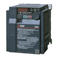
Mitsubishi Electric FR-E840-0040 Instruction Manual (Connection (226 pages)
Compact, high functionality inverters
Brand:
Mitsubishi Electric
| Category:
Inverter
| Size: 9 MB
Table of Contents
Table of Contents
2
Safety Instructions
5
Electric Shock Prevention
6
Fire Prevention
6
Injury Prevention
7
Additional Instructions
8
General Instruction
12
Harmonic Suppression Guidelines
15
Chapter 1 Introduction
15
Product Checking and Accessories
16
Inverter Model
16
Rating Plate
16
How to Read the SERIAL Number
18
Component Names
19
Standard Model
19
Ethernet Model
20
Operation Steps
23
Related Manuals
26
Chapter 2 Installation and Wiring
29
Peripheral Devices
29
Inverter and Peripheral Devices
29
Peripheral Devices (Standard Model / Ethernet Model / Safety Communication Model)
32
Peripheral Devices (IP67 Model)
34
Removal and Reinstallation of the
36
Removal and Reinstallation of the Front Cover
36
Installation of the Inverter and Enclosure Design
42
Inverter Installation Environment
42
Amount of Heat Generated by the Inverter (Standard Model / Ethernet Model / Safety Communication Model)
44
Amount of Heat Generated by the Inverter (IP67 Model)
45
Output Current Reduction When the Surrounding Air Temperature Is between 50°C and 60°C (Standard Model / Ethernet Model / Safety Communication Model)
46
Output Current Reduction When the Surrounding Air Temperature Is between 40°C and 50°C (IP67 Model)
47
Standby Power Consumption by the Inverter (Standard Model / Ethernet Model / Safety Communication Model)
47
Standby Power Consumption by the Inverter (IP67 Model)
48
Cooling System Types for Inverter Enclosure
48
Inverter Installation
49
Inverter Placement
49
Terminal Connection Diagrams
52
Main Circuit Terminals (Standard Model / Ethernet Model / Safety Communication Model)
63
Details on the Main Circuit Terminals
63
Main Circuit Terminal Layout and Wiring to Power Supply and Motor
63
Applicable Cables and Wiring Length
66
Earthing (Grounding) Precautions
72
Main Circuit Terminals (IP67 Model)
73
Details on the Main Circuit Terminals
73
Main Circuit Terminals (Connector) Layout and Wiring to Power Supply and Motor
73
Wiring Method
74
Applicable Cables and Wiring Length
75
Earthing (Grounding) Precautions
77
Control Circuit (Standard Model / Ethernet Model / Safety Communication Model)
78
Details on the Control Circuit Terminals (Standard Model)
78
Input Signal
78
Output Signal
79
Common Terminal
80
Details on the Control Circuit Terminals (Ethernet Model)
81
Details on the Control Circuit Terminals (Safety Communication Model)
83
Control Logic (Sink/Source) Change (Standard Model / Ethernet Model)
85
Wiring of Control Circuit
87
Control Circuit Terminal Layout
87
Wiring Method
88
Wiring Connection
88
Wire Removal
90
Signal Inputs by Contactless Switches
91
Wiring Precautions
91
Safety Stop Function (Standard Model / Ethernet Model)
92
Function Description
92
Connection Diagram
92
Safety Communication Function (Safety Communication Model)
94
Control Circuit (IP67 Model)
96
Details on the Control Circuit Terminals
96
Wiring of Control Circuit
98
When Supplying 24 V External Power to the Control Circuit
101
Safety Communication Function
102
Connection to a Motor with Encoder (Vector Control)
105
Encoder Cable
107
Communication Connectors and Terminals
112
PU Connector (Standard Model)
112
Communication Operation
112
Ethernet Connector (Ethernet Model / Safety Communication Model)
113
Ethernet Communication Specifications
113
Connection Cable
113
Wiring Method
113
Wiring Precautions
114
Network Configuration
114
Ethernet Connector (IP67 Model)
115
USB Connector
116
USB Device Communication
116
Connection of Stand-Alone Option Units
118
Communication Model)
118
Connection of the Brake Resistor (FR-E820-0030(0.4K) or Higher, FR-E840-0016(0.4K) or Higher, FR-E820S-0030(0.4K) or Higher, and FR-E810W-0030(0.4K) or Higher)
118
Connection of the Brake Unit (FR-BU2)
122
Connection of the High Power Factor Converter (FR-HC2) (Standard Model / Ethernet Model)
124
Connection of the Multifunction Regeneration Converter (FR-XC) (Standard Model / Ethernet Model)
125
Connection of the Power Regeneration Common Converter (FR-CV) (Standard Model / Ethernet Model)
126
Connection of the AC Reactor (FR-HAL)
127
Connection of the DC Reactor (FR-HEL)
128
Connection of Stand-Alone Option Units (IP67 Model)
129
2.12.1 Connection of the Brake Resistor
129
Connection of the Brake Unit (FR-BU2)
130
Connection of the AC Reactor (FR-HAL)
132
Chapter 3 Precautions for Use of the Inverter
134
Electro-Magnetic Interference (EMI) and Leakage Currents
135
Leakage Currents and Countermeasures
135
Selecting the Rated Sensitivity Current for the Earth Leakage Circuit Breaker
136
Techniques and Measures for Electromagnetic Compatibility (EMC)
137
Power Supply Harmonics
140
Harmonic Suppression Guidelines in Japan
140
Conversion Factor
141
Installation of a Reactor
144
Power Shutdown and Magnetic Contactor (MC)
145
Countermeasures against Deterioration of the 400 V Class Motor Insulation
147
Checklist before Starting Operation
148
Failsafe System Which Uses the Inverter
151
Specifications
154
Inverter Rating
155
Motor Rating
161
Mitsubishi Electric High-Performance Energy-Saving Motor with Encoder SF-PR-SC
161
Mitsubishi Electric Vector Control Dedicated Motor SF-V5RU
163
PM Motor MM-GKR
165
Motor Specifications
165
PM Motor EM-A
169
Motor Torque
172
Common Specifications
173
Outline Dimension Drawings
176
Inverter Outline Dimension Drawings (Standard Model)
176
Inverter Outline Dimension Drawings (Ethernet Model / Safety Communication Model)
185
Inverter Outline Dimension Drawings (IP67 Model)
194
Dedicated Motor Outline Dimension Drawings
196
Chapter 5 Appendix
214
How to Check Specification Changes
215
Details of Specification Changes
215
Instructions for EAC
222
Compliance with the UK Certification Scheme
222
Restricted Use of Hazardous Substances in Electronic and Electrical Products
223
Referenced Standard (Requirement of Chinese Standardized Law)
223
Warranty
224
Advertisement
Mitsubishi Electric FR-E840-0040 Instruction Manual (140 pages)
Connection
Brand:
Mitsubishi Electric
| Category:
Inverter
| Size: 5 MB
Table of Contents
Table of Contents
2
Safety Instructions
4
Chapter 1 Introduction
13
Product Checking and Accessories
14
Component Names
16
Operation Steps
19
Related Manuals
21
Chapter 2 Installation and Wiring
23
Peripheral Devices
23
Inverter and Peripheral Devices
23
Peripheral Devices
26
Removal and Reinstallation of the
28
Installation of the Inverter and Enclosure Design
34
Inverter Installation Environment
34
Amount of Heat Generated by the Inverter
36
Cooling System Types for Inverter Enclosure
36
Inverter Installation
37
Terminal Connection Diagrams
40
Main Circuit Terminals
46
Details on the Main Circuit Terminals
46
Main Circuit Terminal Layout and Wiring to Power Supply and Motor
47
Applicable Cables and Wiring Length
48
Earthing (Grounding) Precautions
52
Control Circuit
54
Details on the Control Circuit Terminals (Standard Model)
54
Details on the Control Circuit Terminals (Ethernet Model)
57
Details on the Control Circuit Terminals (Safety Communication Model)
59
Control Logic (Sink/Source) Change (Standard Model / Ethernet Model)
61
Wiring of Control Circuit
63
Wiring Precautions
66
Safety Stop Function (Standard Model / Ethernet Model)
67
Safety Communication Function (Safety Communication Model)
68
Connection to a Motor with Encoder (Vector Control)
71
Communication Connectors and Terminals
78
PU Connector (Standard Model)
78
Ethernet Connector (Ethernet Model / Safety Communication Model)
79
USB Connector
81
Connection of Stand-Alone Option Units
82
Connection of the Brake Resistor (FR-E820-0030(0.4K) or Higher, FR-E840-0016(0.4K) or Higher, and FR-E820S-0030(0.4K) or Higher)
82
Connection of the Brake Unit (FR-BU2)
85
Connection of the High Power Factor Converter (FR-HC2) (Standard Model / Ethernet Model)
86
Connection of the Multifunction Regeneration Converter (FR-XC) (Standard Model / Ethernet Model)
87
Connection of the Power Regeneration Common Converter (FR-CV) (Standard Model / Ethernet Model)
88
Connection of the DC Reactor (FR-HEL)
89
Chapter 3 Precautions for Use of the Inverter
91
Electro-Magnetic Interference (EMI) and Leakage Currents
91
Leakage Currents and Countermeasures
91
Techniques and Measures for Electromagnetic Compatibility (EMC)
93
Power Supply Harmonics
96
Harmonic Suppression Guidelines in Japan
96
Installation of a Reactor
100
Power Shutdown and Magnetic Contactor (MC)
101
Countermeasures against Deterioration of the 400 V Class Motor Insulation
103
Checklist before Starting Operation
104
Failsafe System Which Uses the Inverter
107
Chapter 4 Specifications
111
Inverter Rating
111
Motor Rating
114
Common Specifications
117
Outline Dimension Drawings
119
Inverter Outline Dimension Drawings (Standard Model)
119
Inverter Outline Dimension Drawings (Ethernet Model / Safety Communication Model)
125
Dedicated Motor Outline Dimension Drawings
131
Chapter 5 Appendix
136
How to Check the Specification Change
137
Specification Change
137
Advertisement
Related Products
Mitsubishi Electric FR-E840-0047-HVC
Mitsubishi Electric FR-E840-0016E
Mitsubishi Electric FR-E840-0026
Mitsubishi Electric FR-E840-0016SCE
Mitsubishi Electric FR-E840-0018-HVC
Mitsubishi Electric FR-E840-0030-HVC
Mitsubishi Electric FR-E840-0059-HVC
Mitsubishi Electric FR-E840-0094-HVC
Mitsubishi Electric FR-E840-0095
Mitsubishi Electric FR-E840-0060
Mitsubishi Electric Categories
Air Conditioner
Controller
Projector
Inverter
Heat Pump
More Mitsubishi Electric Manuals
Login
Sign In
OR
Sign in with Facebook
Sign in with Google
Upload manual
Upload from disk
Upload from URL