Sign In
Upload
Manuals
Brands
Mennekes Manuals
Automobile Battery Charger
AMTRON Light
Mennekes AMTRON Light Manuals
Manuals and User Guides for Mennekes AMTRON Light. We have
5
Mennekes AMTRON Light manuals available for free PDF download: Operating And Installation Manual, Installation Manual, Operation Manual For User, Installation Instructions Manual, Manual
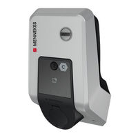
Mennekes AMTRON Light Operating And Installation Manual (260 pages)
Charge Control
Brand:
Mennekes
| Category:
Automobile Accessories
| Size: 3.77 MB
Table of Contents
Deutsch
3
Table of Contents
3
Zu diesem Dokument
5
Homepage
5
Kontakt
5
Warnhinweise
5
Verwendete Symbolik
5
Zu Ihrer Sicherheit
7
Zielgruppen
7
Bestimmungsgemäße Verwendung
7
Bestimmungswidrige Verwendung
7
Grundlegende Sicherheitshinweise
8
Sicherheitsaufkleber
8
Produktbeschreibung
10
Wesentliche Ausstattungsmerkmale
10
Typenschild
10
Lieferumfang
11
Produktaufbau
11
Betriebsarten
12
Lademodi bei Solar-Laden
13
LED-Infofeld
13
Ladeanschlüsse
14
Technische Daten
15
Installation
17
Standort Auswählen
17
Zulässige Umgebungsbedingungen
17
Vorarbeiten am Standort
17
Vorgelagerte Elektroinstallation
17
Schutzeinrichtungen
18
Produkt Transportieren
19
Produkt Öffnen
19
Produkt an der Wand Montieren
19
Elektrischer Anschluss
20
Netzformen
20
Produkt auf Einphasigen Betrieb Einrichten
21
Produkt Vernetzen
21
Spannungsversorgung
21
Inbetriebnahme
22
Anschlüsse auf der ECU
22
Produkt Einschalten
22
Verbindung zur ECU Einrichten
22
Über USB
23
Über Ethernet
23
Über das Netzwerk
23
Aufbau der Weboberfläche
24
Weboberfläche Bedienen
24
Statusinformationen Einsehen
24
Maximalen Ladestrom Einstellen
24
Betriebsart „Standalone mit Autorisierung
25
Produkt in ein Lokales Netzwerk Einbinden
25
Betriebsart „Standalone Autostart
25
Betriebsarten Einstellen
25
Betriebsart „Standalone Backend-System
26
Betriebsart „Vernetzt
27
Weitere Funktionen Einstellen
27
Externen Energiezähler Anbinden
27
Downgrade bei Verwendung eines Energiezählers vom Typ Siemens PAC2200
30
Schnittstelle (Modbus TCP Server) für Energiemanagementsysteme Aktivieren
31
Schnittstelle (Eebus) für Energiemanagementsysteme Aktivieren
32
Schnittstelle (SEMP) für Energiemanagementsysteme Aktivieren
32
Vorgenommene Konfiguration auf Werkseinstellung Zurücksetzen
33
Produkt Prüfen
33
Produkt Schließen
33
Fahrzeug Laden
35
Autorisieren
35
Bedienung
35
Benutzer-Weboberfläche
36
Benutzer-Weboberfläche Aufrufen
36
Aufbau der Benutzer-Weboberfläche
37
Benutzer-Weboberfläche Bedienen
37
Lademodus Wechseln
38
Ladestatistiken Exportieren
38
Zeitserver Angeben
38
Whitelist Verwalten
38
Instandhaltung
39
Wartung
39
Reinigung
40
Firmware Update
40
Firmware Update von allen Produkten IM Netzwerk Parallel Durchführen
40
Firmware-Update auf Version 5.22.4: Passwort der Benutzer-Weboberfläche („User")
41
Störungsbehebung
42
Störungsmeldungen
42
Ersatzteile
42
Ladestecker Manuell Entriegeln
42
Außerbetriebnahme
44
Lagerung
44
Entsorgung
44
EU-Konformitätserklärung
45
English
47
About this Document
49
Contact
49
Symbols Used
49
Warning Notices
49
Website
49
Basic Safety Information
50
For Your Safety
50
Improper Use
50
Intended Use
50
Target Groups
50
Safety Labels
51
Main Features
52
Product Description
52
Rating Plate
52
Delivery Contents
53
Product Structure
53
Operating Modes
54
LED Information Panel
55
Solar Charging Modes
55
Charging Connections
56
Technical Data
57
Installation
59
Permissible Ambient Conditions
59
Preparatory Work on Site
59
Select Location
59
Upstream Electrical Installation
59
Protective Devices
60
Installing the Product on the Wall
61
Opening the Product
61
Transporting the Product
61
Electrical Connection
62
Network Configurations
62
Networking the Product
63
Power Supply
63
Set the Product up for Single-Phase Operation
63
Commissioning
64
Connections on the ECU
64
Setting up a Connection to the ECU
64
Switching on the Product
64
Via Ethernet
65
Via the Network
65
Via USB
65
Integrating the Product into a Local Network
66
Operating the Web Interface
66
Setting the Maximum Charging Current
66
Structure of the Web Interface
66
View Status Information
66
Setting Operating Modes
67
Standalone Autostart" Operating Mode
67
Standalone with Authorisation" Operating Mode
67
Networked" Operating Mode
68
Standalone Backend-System" Operating Mode
68
Connecting an External Energy Meter
69
Setting Other Functions
69
Downgrade When Using an Energy Meter Type Siemens PAC2200
71
Activate the Interface (Modbus TCP Server) for Energy Management Systems
72
Activating the Interface (Eebus) for Energy Management Systems
72
Activating the Interface (SEMP) for Energy Management Systems
73
Closing the Product
74
Reset the Configuration to the Factory Setting
74
Testing the Product
74
Authorisation
75
Charging the Vehicle
75
Operation
75
Calling up the User Web Interface
76
User Web Interface
76
Structure of the User Web Interface
77
Using the User Web Interface
77
Changing the Charging Mode
78
Exporting Charging Statistics
78
Specifying a Time Server
78
Whitelist Management
78
Maintenance
79
Servicing
79
Cleaning
80
Execute Firmware Updates for All Products in the Network in Parallel
80
Firmware Update
80
Firmware Update to Version 5.22.4: Pass
81
Word for the User Web Interface ("User")
81
Fault Messages
82
Spare Parts
82
Troubleshooting
82
Unlocking the Charging Plug Manually
82
Disposal
84
Storage
84
Taking out of Service
84
EU Declaration of Conformity
85
Français
87
Contact
89
Mentions D'avertissement
89
Site Web
89
Symboles Utilisés
89
À Propos du Présent Document
89
Groupes Cibles
90
Pour Votre Sécurité
90
Utilisation Conforme
90
Utilisation Non Conforme
90
Autocollant de Sécurité
91
Consignes de Sécurité Fondamentales
91
Description du Produit
93
Principales Caractéristiques D'équipement
93
Plaque Signalétique
94
Étendue de la Livraison
94
Modes de Fonctionnement
95
Structure du Produit
95
Modes de Charge en cas de Recharge Solaire
96
Champ D'informations à del
97
Connexions de Charge
97
Caractéristiques Techniques
99
Choix de L'emplacement
101
Conditions Ambiantes Admissibles
101
Installation
101
Installation Électrique en Amont
101
Travaux Préliminaires Sur le Site
101
Dispositifs de Protection
102
Montage Mural du Produit
103
Ouverture du Produit
103
Transport du Produit
103
Configurations du Réseau
104
Raccordement Électrique
104
Alimentation Électrique
105
Configuration du Produit pour un Fonctionnement Monophasé
105
Mise en Réseau du Produit
105
Configuration de la Connexion à L'ecu
107
Mise en Marche du Produit
107
Mise en Service
107
Raccords Sur L'ecu
107
Via Ethernet
108
Via le Réseau
108
Via USB
108
Structure de L'interface Web
109
Utilisation de L'interface Web
109
Affichage des Informations à Propos du Statut
110
Configuration des Modes de Fonctionnement
110
Intégration du Produit à un Réseau Local
110
Mode de Fonctionnement " Standalone Autostart
110
Réglage du Courant de Charge Maximal
110
Mode de Fonctionnement " Standalone Avec Autorisation
111
Mode de Fonctionnement " Standalone Backend-System
111
Configuration D'autres Fonctions
112
Connexion du Compteur D'énergie Externe
112
Mode de Fonctionnement " en Réseau
112
Downgrade en cas D'utilisation du Compteur D'énergie du Type Siemens PAC2200
115
Activation de L'interface (Serveur Modbus TCP) pour Systèmes de Gestion de L'énergie
116
Activation de L'interface (Eebus) pour les
117
Activation de L'interface (SEMP) pour les Systèmes de Gestion de L'énergie
117
Systèmes de Gestion de L'énergie
117
Contrôle du Produit
118
Restauration des Paramètres Par Défaut de la Configuration
118
Fermeture du Produit
119
Autorisation
120
Charge du Véhicule
120
Utilisation
120
Accès à L'interface Web Utilisateur
121
Interface Web Utilisateur
121
Changement du Mode de Charge
123
Exportation des Statistiques de Charge
123
Saisie D'un Serveur de Temps
123
Structure de L'interface Web Utilisateur
123
Utilisation de L'interface Web Utilisateur
123
Gestion de la Whitelist
124
Entretien
125
Maintenance
125
Mise à Jour du Firmware
126
Nettoyage
126
Installation Parallèle de la Mise à Jour du Firmware Sur Tous les Produits au sein du Réseau
127
Mise à Jour du Firmware à la Version 5.22.4 : Mot de Passe de L'interface Web Utilisateur (" User ")
127
Dépannage
128
Déverrouillage Manuel de la Fiche de Charge
128
Messages de Panne
128
Pièces de Rechange
128
Mise au Rebut
130
Mise Hors Service
130
Stockage
130
11 Déclaration de Conformité UE
131
Italiano
133
Avvisi DI Pericolo
135
Contatto
135
Home Page
135
In Merito al Presente Documento
135
Simboli Utilizzati
135
Gruppi Target
136
Per la Vostra Sicurezza
136
Uso Conforme Alla Destinazione
136
Uso Non Conforme Alla Destinazione Prevista
136
Adesivo DI Sicurezza
137
Indicazioni DI Sicurezza Fondamentali
137
Caratteristiche Essenziali DI Dotazione
139
Descrizione del Prodotto
139
Targhetta Identificativa
140
Volume DI Fornitura
140
Modalità Operative
141
Struttura del Prodotto
141
Campo DI Informazione a LED
142
Modalità Per la Ricarica Solare
142
Connettori Per la Ricarica
143
Dati Tecnici
145
Condizioni Ambientali Ammesse
147
Impianto Elettrico a Monte
147
Installazione
147
Operazioni Preliminari Sul Posto
147
Selezione Della Posizione
147
Dispositivi DI Protezione Integrati
148
Apertura del Prodotto
149
Montaggio del Prodotto a Parete
149
Trasporto del Prodotto
149
Alimentazione DI Tensione
151
Collegamento Elettrico
151
Forme DI Rete
151
Impostazione del Prodotto Su Funzionamento Monofase
151
Collegamento in Rete del Prodotto
152
Collegamenti Dell'unità ECU
153
Impostazione Collegamento Alla ECU
153
Inserzione del Prodotto
153
Messa in Funzione
153
Via Ethernet
154
Via la Rete
154
Via USB
154
Impostazione Della Corrente DI Carico Massima
155
Struttura Dell'interfaccia Web
155
Uso Dell'interfaccia Web
155
Visualizzazione Delle Informazioni DI Stato
155
Collegamento del Prodotto in una Rete Locale
156
Impostazione Delle Modalità Operative
156
Modalità Operativa „Standalone Autostart
156
Modalità Operativa „Standalone con Autorizzazione
156
Modalità Operativa „Standalone Backend-System
157
Collegamento DI un Contatore DI Energia Esterno
158
Impostazione DI Altre Funzioni
158
Modalità Operativa "Collegato in Rete
158
Downgrade in Caso DI Impiego DI un Contatore DI Energia DI Tipo Siemens PAC2200
161
Attivazione Interfaccia (Modbus TCP Server) Per Sistemi DI Gestione Energia
162
Attivazione Interfaccia (Eebus) Per Sistemi DI Gestione Dell'energia
163
Attivazione Interfaccia (SEMP) Per Sistemi DI Gestione Dell'energia
163
Chiusura del Prodotto
164
Controllo del Prodotto
164
Ripristino Della Configurazione Effettuata Sull'impostazione DI Fabbrica
164
Autorizzazione
166
Comando
166
Ricarica del Veicolo
166
Interfaccia Web Dell'utente
167
Richiamo Dell'interfaccia Web Dell'utente
167
Struttura Dell'interfaccia Web Dell'utente
168
Cambio Modalità DI Ricarica
169
Esportazione Statistiche DI Ricarica
169
Gestione Della Whitelist
169
Indicazione DI un Time Server
169
Uso Dell'interfaccia Web Dell'utente
169
Manutenzione
170
Manutenzione, Riparazione E Revisione
170
Aggiornamento del Firmware
172
Aggiornamento del Firmware Alla Versione 5.22.4: Password Per Accedere All'interfaccia Web Dell'utente ("User")
172
Esecuzione in Parallelo Dell'aggiornamento del Firmware DI Tutti I Prodotti Nella Rete
172
Pulizia
172
Eliminazione DI Anomalie
173
Pezzi DI Ricambio
173
Sblocco Manuale Della Spina DI Ricarica
173
Segnalazioni DI Guasto
173
Immagazzinamento
175
Messa Fuori Servizio
175
Smaltimento
175
Dichiarazione DI Conformità UE
176
Dutch
177
Contact
179
Gebruikte Symbolen
179
Homepage
179
Over Dit Document
179
Waarschuwingen
179
Beoogd Gebruik
180
Doelgroepen
180
Oneigenlijk Gebruik
180
Voor Uw Veiligheid
180
Fundamentele Veiligheidsinstructies
181
Veiligheidsstickers
181
Essentiële Uitrustingskenmerken
183
Productbeschrijving
183
Typeplaatje
183
Leveringsomvang
184
Productopbouw
184
Bedrijfsmodi
185
Laadmodi Bij Laden Op Zonne-Energie
186
LED-Infoveld
186
Laadaansluiting
187
Technische Gegevens
189
Installatie
191
Locatie Kiezen
191
Toelaatbare Omgevingsomstandigheden
191
Veiligheidsvoorzieningen
192
Voorbereidende Werkzaamheden Ter Plaatse
192
Voorgeschakelde Elektrische Installatie
192
Product Openen
193
Product Vervoeren
193
Product Aan de Wand Monteren
194
Elektrische Aansluiting
195
Netvormen
195
Stroomvoorziening
195
Product Instellen Op Eenfasig Bedrijf
196
Product Koppelen
196
Aansluitingen Op de ECU
197
Inbedrijfstelling
197
Product Inschakelen
197
Verbinding Naar ECU Instellen
197
Via Ethernet
198
Via Het Netwerk
198
Via USB
198
Maximale Laadstroom Instellen
199
Statusinformatie Bekijken
199
Structuur Van de Webinterface
199
Webinterface Bedienen
199
Bedrijfsmodi Instellen
200
Bedrijfsmodus "Autostart"Bedrijfsmodus "Standalone Autostart
200
Bedrijfsmodus „Standalone Met Autorise
200
Product Integreren in Een Lokaal Netwerk
200
Bedrijfsmodus "Standalone Backend- System
201
Andere Functies Instellen
202
Bedrijfsmodus "Gekoppeld
202
Externe Energiemeter Aansluiten
202
Downgrade Bij Gebruik Van Een Energiemeter Van Het Type Siemens PAC2200
205
Interface (Modbus TCP-Server) Voor Energiemanagementsystemen Activeren
206
Interface (Eebus) Voor Energiemanagementsystemen Activeren
207
Interface (SEMP) Voor Energiemanagementsystemen Activeren
207
Gemaakte Configuratie Resetten Naar de Fabrieksinstelling
208
Product Sluiten
208
Product Testen
208
Autoriseren
210
Bediening
210
Voertuig Laden
210
Gebruikers-Webinterface
211
Gebruikers-Webinterface Oproepen
211
Gebruikers-Webinterface Bedienen
212
Structuur Van de Gebruikers-Webinterface
212
Laadmodus Wisselen
213
Laadstatistieken Exporteren
213
Tijdserver Aangeven
213
Whitelist Beheren
213
Instandhouding
214
Onderhoud
214
Firmware-Update Van alle Producten in Het Netwerk Parallel Uitvoeren
215
Reiniging
215
Update Firmware
215
Firmware-Update Naar Versie 5.22.4: Wachtwoord Van de Gebruikers-Webinterface ("User")
216
Laadstekker Handmatig Ontgrendelen
217
Reserveonderdelen
217
Storingsmeldingen
217
Storingsoplossing
217
Afvoeren
219
Buitendienststelling
219
Opslag
219
EU-Conformiteitsverklaring
220
Advertisement
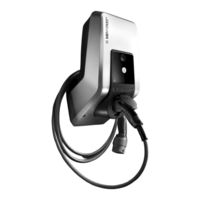
Mennekes AMTRON Light Installation Manual (172 pages)
Charging station for electric vehicles
Brand:
Mennekes
| Category:
Battery Charger
| Size: 13.72 MB
Table of Contents
Deutsch
2
Table of Contents
2
1 Allgemeines
3
Aufbau der Installationsanleitung
3
2 Sicherheit
3
Allgemeines zur Sicherheit
3
Sicherheitshinweise
4
Bestimmungsgemäße Verwendung
4
Qualifikation des Personals
4
Gewährleistung
4
Rücksendung von Geräten
4
3 Produktbeschreibung
5
Allgemeines
5
Optionale Ausstattung
5
Typenschild
6
Lieferumfang
6
Aufbau
7
Außenansicht
7
Innenansicht
8
Komponenten
9
Frontpanel
9
CPX-Kommunikationsbox
9
4 Technische Daten
10
Allgemeine Daten
10
Maximale Querschnitte an den Anschlussklemmen
10
Umgebungsbedingungen
10
5 Installation
11
Standortwahl
11
Auspacken
11
Öffnen der Ladestation
12
Montage
12
Mindestabstände
12
Verlegung der Zuleitung
12
Montage der Ladestation an der Wand
13
Elektrischer Anschluss
14
Spannungsversorgung / Netzanschluss
14
Absicherung und Personenschutz
14
Anschlussklemmen
15
6 Inbetriebnahme
16
Einstellung der Konfigurationsschalter
16
Einstellung der Ladestrombegrenzung
16
Einstellung des Farbschemas des LED- Infofeldes
17
Einschalten des Gerätes
17
Prüfung der Ladestation
17
Schließen der Ladestation
18
7 Bedienung
18
Ladekabelaufhängung
18
LED-Infofeld
19
Multifunktionstaster
19
Beenden eines Laufenden Ladevorgangs
19
Wiedereinschalten des Fehlerstrom- und Leitungsschutzschalters
20
Testen des Integrierten Fehlerstromschutzschalters (FI)
20
Quittieren von Störungen
20
Schlüsselschalter
20
Laden des Fahrzeugs
20
Starten des Ladevorgangs
20
Beenden des Ladevorgangs
21
Spannungsausfall während des Ladevorgangs
21
8 Instandhaltung
22
Wartungsplan
22
9 Störungsbehebung
23
Störungsbehebung durch eine Elektrofachkraft
23
Notentriegelung des Ladesteckers
25
Systemüberwachung
25
10 Demontage, Lagerung und Entsorgung
26
Demontage
26
Lagerung
26
Entsorgung
26
11 Anhang
27
Zubehör
27
Glossar
27
Index
28
English
30
1 General
31
Structure of the Installation Instructions
31
2 Safety
31
General Safety Information
31
Safety Information
32
Intended Use
32
Qualification of Personnel
32
Warranty
32
Returning Devices
32
3 Product Description
33
General Information
33
Optional Equipment
33
Identification Plate
34
Delivery Contents
34
Assembly
35
Exterior View
35
Interior View
36
Components
37
Front Panel
37
CPX Communication Box
37
4 Technical Data
38
General Data
38
Maximum Cable Cross-Sections at Terminals
38
Ambient Conditions
38
5 Installation
39
Choice of Location
39
Unpacking
39
Opening the Charging Station
40
Assembly
40
Minimum Distances
40
Installing the Supply Cable
40
Installing the Charger Station on the Wall
41
Electrical Connection
42
Voltage Supply / Supply Network Connection
42
Safeguarding and Personal Protection
42
Terminals
43
6 Commissioning
44
Setting the Configuration Switches
44
Setting the Charging Current Upper Limit
44
Setting the Colour Code of the LED Info Bar16
45
Switching on the Device
45
Checking the Charging Station
45
Closing the Charging Station
46
7 Operation
46
Charing Cable Storage
46
LED Info Bar
47
Multi-Function Button
47
Terminating an On-Going Charging Process
47
Re-Activating the Residual Current Circuit Breaker and Circuit Breaker
48
Testing the Integrated Residual Current Circuit Breaker (RCCB)
48
Acknowledging Faults
48
Key Switch
48
Charging the Vehicle
48
Starting the Charging Process
48
Terminating the Charging Process
49
Power Failure During Charging Process
49
8 Maintenance
50
Maintenance Plan
50
9 Troubleshooting
51
Troubleshooting by a Qualified Electrician
51
Emergency Release of Charging Plug
53
System Monitoring
53
10 Disassembly, Storage and Disposal
54
Disassembly
54
Storage
54
Disposal
54
11 Appendix
55
Accesories
55
Glossary
55
Index
56
Français
86
1 Généralités
87
Structure des Instructions D'installation
87
2 Sécurité
87
Généralités Sur la Sécurité
87
Consignes de Sécurité
88
Utilisation Conforme
88
Qualification du Personnel
88
Garantie
88
Renvoi D'équipements
88
3 Description du Produit
89
Généralités
89
Équipement Optionnel
89
Plaque Signalétique
90
Éléments Livrés
90
Constitution
91
Extérieur
91
Intérieur
92
Composants
93
Panneau Avant
93
Coffret de Communication CPX
93
4 Caractéristiques Techniques
94
Caractéristiques Générales
94
Sections Maximales Sur Les Bornes de Connexion
94
Conditions Ambiantes
94
5 Installation
95
Choix du Site
95
Déballer L'appareil
95
Ouverture de la Station de Charge
96
Montage
96
Distances Minimales
96
Installation de la Ligne D'alimentation
96
Montage Mural de la Station de Charge
97
Raccordement Électrique
98
Alimentation en Tension / Alimentation Sur Secteur
98
Protection Par Fusibles Et Protection des Personnes
98
Bornes de Connexion
99
6 Mise en Service
100
Réglage des Interrupteurs de Configuration
100
Réglage de la Limitation du Courant de Charge
100
Réglage du Schéma de Couleurs du Champ D'informations À del
101
Mise en Marche de L'appareil
101
Contrôle de la Station de Charge
101
Fermeture de la Station de Charge
102
7 Manipulation
102
Suspension du Câble de Charge
102
Champ D'informations À del
103
Touche Multifonctions
103
Fin du Cycle de Charge en Cours
103
Réarmement du Disjoncteur Différentiel Et du Disjoncteur de Protection de Circuit
104
Test du Disjoncteur Différentiel Intégré (DDR)19
104
Acquittement D'anomalies
104
Interrupteur À Clé
104
Charge du Véhicule
104
Démarrage du Cycle de Charge
104
Fin du Cycle de Charge
105
Défaillance de Tension Durant Le Cycle de Charge
105
8 Maintenance
106
Calendrier de Maintenance
106
9 Dépannage
107
Dépannage Par un Électricien Spécialisé
107
Déverrouillage D'urgence de la Fiche de Charge
109
Surveillance du Système
109
10 Démontage, Entreposage Et Élimination
110
Démontage
110
Entreposage
110
Élimination
110
11 Annexe
111
Accessoires
111
Glossaire
111
Index
112
Mennekes AMTRON Light Operation Manual For User (100 pages)
Charging station for Electric Vehicles
Brand:
Mennekes
| Category:
Automobile Battery Charger
| Size: 5.71 MB
Table of Contents
Deutsch
2
Table of Contents
2
1 Allgemeines
3
Aufbau der Betriebsanleitung
3
2 Sicherheit
3
Allgemeines zur Sicherheit
3
Sicherheitshinweise
4
Bestimmungsgemäße Verwendung
4
Qualifikation des Personals
4
Gewährleistung
4
Rücksendung von Geräten
4
3 Produktbeschreibung
5
Allgemeines
5
Optionale Ausstattung
5
Typenschild
6
Lieferumfang
6
Aufbau
7
Außenansicht
7
Komponenten
8
Frontpanel
8
4 Bedienung
8
Ladekabelaufhängung
8
LED-Infofeld
8
Multifunktionstaster
9
Beenden eines Laufenden Ladevorgangs
9
Wiedereinschalten des Fehlerstrom- und Leitungsschutzschalters
10
Testen des Integrierten Fehlerstromschutzschalters (FI)
10
Quittieren von Störungen
10
Schlüsselschalter
10
Laden des Fahrzeugs
10
Starten des Ladevorgangs
10
Beenden des Ladevorgangs
11
Spannungsausfall während des Ladevorgangs
11
5 Instandhaltung
12
Wartungsplan
12
6 Störungsbehebung
13
Störungsbehebung durch den Betreiber
13
7 Demontage, Lagerung und Entsorgung
15
Demontage
15
Lagerung
15
Umgebungsbedingungen
15
Entsorgung
15
Index
16
8 Anhang
16
English
18
1 General
19
Structure of the Operating Manual
19
2 Safety
19
General Safety Information
19
Safety Information
20
Intended Use
20
Qualification of Personnel
20
Warranty
20
Returning Devices
20
3 Product Description
21
General Information
21
Optional Equipment
21
Identification Plate
22
Delivery Contents
22
Assembly
23
Exterior View
23
Front Panel
24
4 Operation
24
Charing Cable Storage
24
LED Info Bar
25
Multi-Function Button
25
Terminating an On-Going Charging Process
25
Re-Activating the Residual Current Circuit Breaker and Circuit Breaker
26
Testing the Integrated Residual Current Circuit Breaker (RCCB)
26
Acknowledging Faults
26
Key Switch
26
Charging the Vehicle
26
Starting the Charging Process
26
Terminating the Charging Process
27
Power Failure During Charging Process
27
5 Maintenance
28
Maintenance Plan
28
6 Troubleshooting
29
Troubleshooting by the Operator
29
7 Disassembly, Storage and Disposal
31
Disassembly
31
Storage
31
Ambient Conditions
31
Disposal
31
8 Appendix
32
Accesories
32
Glossary
32
Index
33
Français
50
1 Généralités
51
Structure du Mode D'emploi
51
2 Sécurité
51
Généralités Sur la Sécurité
51
Consignes de Sécurité
52
Utilisation Conforme
52
Qualification du Personnel
52
Garantie
52
Renvoi D'équipements
52
3 Description du Produit
53
Généralités
53
Équipement Optionnel
53
Plaque Signalétique
54
Éléments Livrés
54
Constitution
55
Extérieur
55
Composants
56
Panneau Avant
56
4 Manipulation
56
Suspension du Câble de Charge
56
Champ D'informations À del
57
Touche Multifonctions
57
Fin du Cycle de Charge en Cours
57
Réarmement du Disjoncteur Différentiel Et du Disjoncteur de Protection de Circuit
58
Test du Disjoncteur Différentiel Intégré (DDR)9
58
Acquittement D'anomalies
58
Interrupteur À Clé
58
Charge du Véhicule
58
Démarrage du Cycle de Charge
58
Fin du Cycle de Charge
59
Défaillance de Tension Durant Le Cycle de Charge
59
5 Maintenance
60
Calendrier de Maintenance
60
6 Dépannage
61
Dépannage Par L'exploitant
61
Démontage
63
Entreposage
63
Conditions Ambiantes
63
Élimination
63
8 Annexe
64
Accessoires
64
Glossaire
64
Index
65
Advertisement
Mennekes AMTRON Light Installation Instructions Manual (48 pages)
Protective Roof
Brand:
Mennekes
| Category:
Power distribution unit
| Size: 1.83 MB
Table of Contents
Deutsch
2
1 Zu diesem Dokument
2
2 Allgemeines
2
Table of Contents
2
3 Zu Ihrer Sicherheit
2
Allgemeine Sicherheitshinweise
2
Arbeitsplatzsicherheit
2
Elektrische Sicherheit
2
Bestimmungsgemäße Verwendung
3
Elektrofachkraft
3
4 Mögliche Fehlanwendungen
3
5 Ladestation Demontieren
3
6 Schutzdach Montieren
4
7 Reinigung von Edelstahl
5
Aloys-Mennekes-Str. 1
6
D-57399 Kirchhundem
6
E-Mail Info@Mennekes.de
6
Elektrotechnik Gmbh & Co. KG
6
Fax +49 (0) 2723 / 41-2
6
Internet Www.mennekes.de
6
Mennekes
6
Spezialfabrik für Steckvorrichtungen
6
Tel
6
English
8
Possible Misuse
9
Intended Use
9
Qualified Electrician
9
Remove Charging Station
9
Install Protective Roof
10
Cleaning of Stainless Steel
11
57399 Kirchhundem
12
Aloys-Mennekes-Str. 1
12
E-Mail Info@Mennekes.de
12
Elektrotechnik Gmbh & Co. KG
12
Fax +49 (0) 2723 / 41-2
12
Germany
12
Internet Www.mennekes.de
12
Mennekes
12
Tel
12
Dutch
14
1 Over Dit Document
14
2 Algemeen
14
3 Voor Uw Veiligheid
14
Veiligheid Op de Werkplek
14
Elektrische Veiligheid
14
4 Mogelijke Verkeerde Toepassingen
15
5 Laadstation Demonteren
15
6 Afdak Monteren
16
7 Reiniging Van Roestvast Staal
17
Aloys-Mennekes-Str. 1
18
D-57399 Kirchhundem
18
E-Mail Info@Mennekes.de
18
Elektrotechnik Gmbh & Co. KG
18
Fax +49 (0) 2723 / 41-2
18
Internet Www.mennekes.de
18
Mennekes
18
Speciale Fabriek Voor Steekverbindingen
18
Tel
18
Français
20
Utilisations Incorrectes Prévisibles
21
Utilisation Conforme
21
Électricien Spécialisé
21
Démontage de la Station de Charge
21
Montage de L'auvent
22
Nettoyage de L'acier Inoxydable
23
Aloys-Mennekes-Str. 1
26
D-57399 Kirchhundem Tél. +49 (0) 2723
26
E-Mail Info@Mennekes.de
26
Elektrotechnik Gmbh & Co. KG
26
Fax +49 (0) 2723 / 41-2
26
Internet Www.mennekes.de
26
Mennekes
26
Norsk
32
Sikkerhet På Arbeidsplassen
32
Mulige Feil Bruk
33
Elektrikere
33
Tiltenkt Bruk
33
Demonter Ladestasjonen
33
Montere Beskyttelsestak
34
Rengjøring Av Rustfritt Stål
35
Aloys-Mennekes-Str. 1
36
D-57399 Kirchhundem
36
E-Post Info@Mennekes.de
36
Faks +49 (0) 2723 / 41-2
36
Internet Www.mennekes.de
36
Tel
36
Mennekes AMTRON Light Manual (29 pages)
Charging station for Electric Vehicles
Brand:
Mennekes
| Category:
Battery Charger
| Size: 6.15 MB
Table of Contents
Table of Contents
2
1 General
3
Structure of the Installation Instructions
3
2 Safety
3
General Safety Information
3
Safety Information
4
Intended Use
4
Qualification of Personnel
4
Warranty
4
Returning Devices
4
3 Product Description
5
General Information
5
Optional Equipment
5
Identification Plate
6
Delivery Contents
6
Assembly
7
Exterior View
7
Interior View
8
Components
9
Front Panel
9
CPX Communication Box
9
4 Technical Data
10
General Data
10
Maximum Cable Cross-Sections at Terminals
10
Ambient Conditions
10
5 Installation
11
Choice of Location
11
Unpacking
11
Opening the Charging Station
12
Assembly
12
Minimum Distances
12
Installing the Supply Cable
12
Installing the Charger Station on the Wall
13
Electrical Connection
14
Voltage Supply / Supply Network Connection
14
Safeguarding and Personal Protection
14
Terminals
15
6 Commissioning
16
Setting the Configuration Switches
16
Setting the Charging Current Upper Limit
16
Setting the Colour Code of the LED Info Bar16
17
Switching on the Device
17
Checking the Charging Station
17
Closing the Charging Station
18
7 Operation
18
Charing Cable Storage
18
LED Info Bar
19
Multi-Function Button
19
Terminating an On-Going Charging Process
19
Re-Activating the Residual Current Circuit Breaker and Circuit Breaker
20
Testing the Integrated Residual Current Circuit Breaker (RCCB)
20
Acknowledging Faults
20
Key Switch
20
Charging the Vehicle
20
Starting the Charging Process
20
Terminating the Charging Process
21
Power Failure During Charging Process
21
Advertisement
Related Products
Mennekes AMTRON Start E
Mennekes AMTRON Pro
Mennekes AMTRON Standard E
Mennekes AMTRON Basic E
Mennekes AMTRON Basic R
Mennekes AMTRON 4You 100 11
Mennekes AMTRON 4You 100 22
Mennekes AMTRON Series
Mennekes AMTRON Premium E
Mennekes AMTRON Premium R
Mennekes Categories
Battery Charger
Automobile Accessories
Cables and connectors
Industrial Equipment
Power distribution unit
More Mennekes Manuals
Login
Sign In
OR
Sign in with Facebook
Sign in with Google
Upload manual
Upload from disk
Upload from URL