Sign In
Upload
Manuals
Brands
Lucent Technologies Manuals
Switch
CBX 500
Lucent Technologies CBX 500 Manuals
Manuals and User Guides for Lucent Technologies CBX 500. We have
4
Lucent Technologies CBX 500 manuals available for free PDF download: Configuration Manual, Installation Manual, Brochure, Specifications
Lucent Technologies CBX 500 Configuration Manual (888 pages)
Brand:
Lucent Technologies
| Category:
Switch
| Size: 9.04 MB
Table of Contents
Section 1
7
Table of Contents
7
Section 2
33
About this Guide
35
What You Need to Know
36
Reading Path
37
How to Use this Guide
40
What's New in this Guide
43
Conventions
44
Related Documents
45
Lucent
45
Third Party
46
Customer Comments
47
Ordering Printed Manuals Online
47
Technical Support
47
Chapter 1 Overview
49
Logical Ports
49
Atm Fcp
50
ATM Trunks
50
ATM over MPLS
51
Pvcs
51
Network-Wide Features
51
Fault-Tolerant Pvcs
52
Rlmi
52
Svcs
52
Cugs
53
Port Security Screening
53
Spvcs
53
SVC Proxy Signaling
53
Pnni
54
Cac
54
ATM Traffic Descriptors
54
CBX 500 Shared SP Threads
54
FCP Rate Profile Tables
55
Priority Routing
55
Reliable Scalable Circuit
55
OSPF Name Aggregation
55
Customer Names
55
Trunk Conditioning
56
Abbreviations and Acronyms
56
Chapter 2 About ATM Logical Ports
57
ATM UNI Concepts
58
ATM UNI DCE and DTE
59
ATM UNI 4.0 Support
60
Using ILMI
61
ILMI VCC Trap Support
62
Using Logical Port Signaling
62
Configurable Control Circuits
63
ILMI and Signaling Example
63
ATM Optimum Cell Trunk
64
Configuring the VPI
64
Configuring the Optimum Trunk for Vpcs
65
IP-Related Connections
65
PVC/SVC VPC Connections
65
ATM Direct Trunk
66
Atm Ce
66
Atm Nni
67
Virtual UNI/NNI
67
Vps and Vcs
68
Figure 2-2. Virtual UNI with VP Multiplexer
68
Setting the Number of Valid Bits in the VPI/VCI
69
VPI/VCI Bit Allocation
69
Table 2-3. Number of Valid Bits in VPI/VCI for CBX 500 or CBX 3500
70
Table 2-4. Number of Valid Bits in VPI/VCI for GX 550
71
Configuring VCC VPI Start and Stop Values for Virtual UNI/NNI
72
Atmompls UNI/NNI
72
About Logical Port Bandwidth
72
Table 2-5. Physical and Logical Port Bandwidth Conversions
73
CBX 500 SP Thread Bandwidth Available for Logical Ports
74
Modifying Logical Port Bandwidth
74
About the Oversubscription Factor
75
About VP Shaping on the CBX 500 and CBX 3500
76
About VP Shaping on the GX 550
77
Administrative Tasks
79
Using Templates
79
Figure 2-3. Choose Template Dialog Box
80
Modifying Switch Configuration Attributes
81
Deleting ATM Logical Ports
83
Deleting Trunks
84
Chapter 3 Configuring CBX or GX Logical Ports
86
Working with ATM Logical Ports
86
Figure 3-2. Managing Logical Ports in the Switch Tab
87
Adding an ATM Logical Port
88
Figure 3-4. Navis EMS-CBGX Switch Object Tree
89
Figure 3-5. Add Logical Port Dialog Box
92
Defining a Logical Port
93
Modifying an ATM Logical Port
94
Figure 3-7. Modify Logical Port Dialog Box
96
Setting Logical Port Attributes
98
General Attributes
100
Administrative Attributes
104
Table 3-3. Add Logical Port: Administrative Tab Fields
105
Configuring VP Shaping on CBX 500 Virtual UNI Logical Ports
109
Modifying the VP Shaping Mode on GX 550 Virtual UNI Logical Ports
111
Figure 3-10. Add Logical Port: ATM Tab (UNI Logical Ports)
112
Table 3-4. Add Logical Port: ATM Tab Fields
113
ILMI/OAM Attributes
118
Table 3-5. Add Logical Port: ILMI/OAM Tab Fields
119
CES Attributes
121
Table 3-6. Add Logical Port: CES Parameters Tab Fields
122
Traffic Descriptor Attributes
125
Figure 3-14. Node-To-Node Forward Traffic Descriptor Dialog Box
126
Figure 3-15. Node-To-Node Reverse Traffic Descriptor Dialog Box
127
Figure 3-17. Trunk Signaling Reverse Traffic Descriptor Dialog Box
128
Optimum Trunk VPI Range Attributes
129
Table 3-7. Add Logical Port: VPI Range Tab Fields
130
ATM FCP Attributes
133
Tunnel VP Shaping Rate Attributes
134
Qos Attributes
135
Figure 3-20. Add Logical Port: Qos Tab
136
Table 3-9. Add Logical Port: Qos Tab Fields
137
Setting SVC Qos Parameters
140
Completing the Logical Port Configuration
141
Configuring Virtual ATM UNI/NNI Logical Ports
142
Configuring Logical Ports for Use with ATM Svcs
143
Chapter 4 Configuring ATM Logical Ports on Frame-Based Modules
146
About ATM Logical Ports
146
ATM Optimum Cell Trunk
147
ATM Optimum Frame Trunk
148
Setting the Number of Valid Bits in VPI/VCI for the B-STDX 9000
149
Using VP Shaping
150
I/O Modules for ATM Services
151
Configuring Ports for ATM DXI/FUNI and ATM Services
152
Logical Port Congestion Thresholds
153
About ATM Logical Port Functions
155
Adding an ATM Logical Port
158
Defining ATM UNI DCE/DTE Logical Ports
159
Table 4-6. Add Logical Port: General Tab Fields
160
Figure 4-2. Add Logical Port: Administrative Tab
162
Table 4-7. Add Logical Port: Administrative Tab Fields
163
Table 4-8. Configuring UNI DCE/DTE Attributes
164
ATM Attributes
165
Table 4-9. Add Logical Port: ATM Tab Fields
166
ILMI/OAM Attributes
170
Congestion Control Attributes
172
Table 4-11. Add Logical Port: Congestion Control Tab Fields
173
Trap Control Attributes
175
Table 4-12. Add Logical Port: Trap Control Tab Fields
176
Priority Frame Attributes
178
Defining ATM Direct Trunk and Optimum Cell Trunk Logical Ports
180
ATM Optimum Cell Trunks
181
Figure 4-8. Select Traffic Shaper Dialog Box
182
Defining ATM Optimum Frame Trunk Logical Ports
184
Table 4-16. Configuring Optimum Frame Trunk Attributes
185
Defining ATM Network Interworking for Frame Relay NNI Logical Ports
186
Link Management Attributes
187
Discard/Congestion Mapping Attributes
191
Table 4-19. Add Logical Port: Discard/Congestion Mapping Tab Fields
192
Optimum Trunk VPI Range Attributes
194
Completing the Logical Port Configuration
196
Chapter 5 About the ATM FCP
200
Modules Supported
200
Supported ATM Service Classes
201
ATM FCP Architecture
202
Closed-Loop Flow Control
203
RM Cell Generation
204
Figure 5-2. Closed-Loop Flow Control
205
CCRM Closed-Loop Flow Control
206
CCRM Closed-Loop Flow Control on a UNI (Traffic Shaping)
207
BCM Closed-Loop Flow Control
208
BCM Closed-Loop Flow Control on a UNI
209
BCM Cell Termination
210
ABR RM Closed-Loop Flow Control
211
Idle Circuits and Idle VC Factor
212
Rate Profile Tables
213
Per-VC Traffic Shaping
214
Figure 5-6. ATM FCP Buffers
215
ATM FCP Discard Mechanisms
216
VP Shaping
217
Shaping Rates
218
Chapter 6 Working with the ATM FCP
220
Configuration Process Overview
220
Figure 6-1. Modify Card Dialog Box
221
Table 6-1. Modify Card: ATM Flow Control Processor Tab Fields
222
Downloading Buffer Threshold and Rate Profile Tables
226
Figure 6-2. Selecting Load Profile
227
Setting Logical Port FCP Attributes
228
Figure 6-4. Add Logical Port: ATM FCP Tab (1-Port Channelized STM/E1 ATM W/Ima Enhanced IOM)
229
Frequently Asked Questions about the FCP
232
What Are the Performance Limitations of the FCP?
233
Is the CI Bit Set When BCM Cells Are Generated?
234
How Is Fair Bandwidth Determined?
235
Why Does the EPD Option Only Work When Enabled for All Circuit Connections?
236
Chapter 7 Configuring Trunks
237
About Administrative Cost
238
About LTP
239
Static and Dynamic Delay
240
Figure 7-2. Modify Trunk Dialog Box
241
About APS
242
Table 7-1. Fast APS Support
243
Table 7-2. Slow APS Support
245
CBX 3500 Notes:
246
Intra-Card APS 1+1
247
APS Resilient UNI
248
About Trunk Backup for the B-STDX 9000
251
Process for Switching over to a Backup Trunk
252
Defining a Trunk
253
Working with Trunks
254
Figure 7-5. Add Trunk Dialog Box
255
Figure 7-6. Select Trunk Endpoints Dialog Box
256
Figure 7-7. Add Trunk Dialog Box with Defined Lport Parameters
257
Table 7-3. Add Trunk: Administrative Tab Fields
258
Using B-STDX 9000 Trunk Backup
261
Table 7-4. Add Trunk: Primary Options Tab Fields
262
Configuring the Backup Trunk for APS Trunk Backup
263
Figure 7-10. Select Primary Trunk Dialog Box
264
Configuring APS Trunk Backup and Fast APS 1+1 for ATM Direct Trunks
265
Figure 7-11. Modify Pport Dialog Box
266
Figure 7-12. Modify Pport: APS Tab
267
Fast APS 1+1
269
Configuring the Backup Trunk for APS Trunk Backup
270
Configuring the Primary Trunk for Fast APS 1+1
271
Configuring Fast APS 1+1 for PNNI Links
272
Table 7-6. Configuring an ATM NNI Logical Port
273
Figure 7-13. Add Logical Port: PNNI Tab
274
Table 7-7. Add Logical Port: PNNI Tab Fields
275
Adding an External Device Object to the Network
278
Figure 7-15. Add Psax Dialog Box
279
Launching the Navis Aqueview Client
280
Modifying a Device on the Map
281
Displaying a Connection on the Map
282
Configuring VNN OSPF
283
Configuring VNN OSPF Area Aggregates
284
Table 7-9. Add VNN Area Aggregate Dialog Box Fields
285
Configuring VNN OSPF Virtual Links
286
Configuring VNN OSPF External Route Aggregates
287
Figure 7-22. Add VNN External Route Aggregation Dialog Box
288
Table 7-11. Add VNN External Route Aggregation Dialog Box Fields
289
Configuring OSPF External Route Aggregates
291
Configuring VNN OSPF Optimized Flooding
293
Interoperability in Lucent Switch Networks
295
Configuring VNN OSPF Name LSA Suppression
297
Chapter 8 Configuring ATM over MPLS Trunks
300
Atmompls Trunk Licensing
300
Managing License Keys with Navis EMS-CBGX
301
How the Atmompls License Works
302
Figure 8-1. One License Key Per NMS
303
About Atmompls Trunks
304
Module Support
305
Multiservice MPLS Core Solution Architecture
306
Atmompls Trunk Features
307
About the Lucent Trunk VPN
308
Chapter 20 Port Security Screening
310
Configuration Overview
310
Configuring Atmompls Trunks
311
Configuring Physical Ports for Atmompls Trunks
312
Figure 8-7. Modify Pport Dialog Box (ATM OC-12C/Stm)
313
Configuring Feeder Logical Ports
314
Figure 8-8. Managing Lports
315
General Attributes
316
Table 8-3. Add Logical Port: General Tab Fields
317
Administrative Attributes
318
Figure 8-11. Add Logical Port: Administrative Tab
319
ATM Attributes
321
ATM FCP Attributes (CBX 500 and CBX 3500)
324
Table 8-6. Add Logical Port: ATM FCP Tab Fields
325
Figure 8-14. Add Logical Port: Qos Tab
326
ILMI/OAM Tab
328
Table 8-8. Add Logical Port: ILMI/OAM Tab
329
Figure 8-16. Add Logical Port: NTM Tab
330
Table 8-9. Add Logical Port: NTM Tab Fields
331
Configuring Atmompls Trunk Logical Ports
332
Atmompls Trunk Logical Port General Attributes
333
Figure 8-19. Add Logical Port: General Tab
334
Atmompls Trunk Logical Port Administrative Attributes
335
Table 8-11. Add Logical Port: Administrative Tab Fields
336
Atmompls Trunk Logical Port Qos Attributes
338
Atmompls Trunk Logical Port Traffic Descriptor Attributes
340
Configuring the Atmompls Trunk
341
Figure 8-24. Add Trunk Dialog Box
342
Table 8-13. Add Trunk: Administrative Tab
343
ATM over MPLS Application Overview
349
Supported Modules
350
PWE3 over an MPLS Core Network
351
Table 9-1. PWE3 Tunnel Switch Guidelines
352
Chapter 9 Configuring ATM over MPLS Gateway Solution on CBX 3500
349
Network-Wide MPLS Settings
353
Configuring MPLS Tunnel Hop Lists
354
Table 9-2. Add Hoplist Dialog Box Fields
355
Configuring Intserv and Diffserv Profiles
356
Figure 9-5. Add Intserv Dialog Box
357
Table 9-3. Add Intserv Dialog Box Fields
358
Creating Diffserv Profiles
359
Table 9-4. Add Diffserv Dialog Box Fields
360
Configuring a Layer 2 Tunnel over MPLS Core Network
362
Configuring Node-Based MPLS Parameters
363
Table 9-5. Modify Switch: MPLS Tab Fields
364
Adding a PPP Lport
365
Figure 9-9. Add Logical Port Dialog Box: Point-To-Point
366
General Attributes for POS Lports
367
Administrative Attributes for POS Lports
368
Qos Attributes for POS Lports
369
Figure 9-11. Add Logical Port: Qos Tab
370
Table 9-9. Add Logical Port: Qos Tab Fields
371
Trap Control Attributes
372
Table 9-10. Add Logical Port: Trap Control Tab
373
MPLS Attributes for POS Lports
374
Table 9-11. Add Logical Port: MPLS Tab Fields
375
Congestion Control Attributes
376
Point to Point Attributes
377
Adding an IP Lport
378
Configuring RSVP-TE on IP Lports
380
Figure 9-18. Modify Rsvpte Dialog Box
381
Specifying the IP Interface Address
384
Configuring OSPF IP Parameters
385
Figure 9-20. Add OSPF IP Interface Dialog Box
386
Configuring a PSN Tunnel
389
Figure 9-21. Add Tunnel: General Tab
390
General Tab Attributes
391
RSVP Signalling Attributes
393
Figure 9-23. Add Tunnel: RSVP-TE Tab
394
Figure 9-24. Add Tunnel: Static Tab
395
Table 9-20. Add Tunnel: Static Tab Fields
396
Configuring a Layer 2 Tunnel
397
Layer 2 Tunnel General Attributes
398
Table 9-21. Add Layer2 Tunnel: General Tab Fields
399
Layer 2 Tunnel ATM Attributes
400
Table 9-22. Add Layer 2 Tunnel: ATM Tab Fields
401
Layer 2 Tunnel VNN Attributes
402
Layer 2 Tunnel PNNI Attributes
404
Table 9-24. Add Layer 2 Tunnel: PNNI Tab Fields
405
Configuring an ATM or FR Circuit over a Layer 2 Tunnel
406
Configuring PWE3 over MPLS Core Network
407
Configuring LDP Entities
408
Table 9-25. Add LDP Entity Dialog Box Fields
409
Configuring a PWE3 Circuit
410
Figure 9-30. Add PVC: Pwe3 Tab
411
Configuring an ATM or FR Circuit
414
Chapter 10 Configuring ATM Pvcs
416
GX 550 VC Provisioning Guidelines
416
PVC Endpoint Rules
418
PVC Establishment Rate Control
419
VC Overload Control
420
About Overload Severity Levels
421
Reliable Scalable Circuit
422
Setting the VPI/VCI Values for Pvcs
423
Accessing Pvcs Using Navis EMS-CBGX
425
Figure 10-2. Right-Clicking on a Circuit
426
Defining a Point-To-Point Circuit Connection
427
Figure 10-4. Select Endpoints Dialog Box
428
About the PVC Tabs
430
Administrative Attributes
431
How PVC Routing Thresholds Interact with Lport Routing Metrics
435
Traffic Type Attributes
436
Table 10-4. Add PVC: Traffic Type Tab Fields
437
User Preference Attributes
440
Table 10-5. Add PVC: User Preference Tab Fields
441
Traffic Management Attributes
445
Table 10-6. Add PVC: Traffic Mgmt Tab Fields
446
Completing the PVC Configuration
447
About Redirect Pvcs
448
Defining Redirect Pvcs
449
Figure 10-9. Select Endpoints Dialog Box (Redirect Pvcs)
450
Configuring Redirect PVC Parameters
451
Figure 10-10. Add Redirect PVC: Administrative Tab
452
Completing the Redirect PVC Configuration
453
Configuring Frame Relay-To-ATM Interworking Circuits
454
Frame Relay-To-ATM Network Interworking
455
Special Network Interworking PVC Configuration Parameters
456
Rate Enforcement
459
Graceful Discard
460
Frame Relay-To-ATM Parameters Conversion Formula
461
Defining Service or Network Interworking PVC Connections
462
Traffic Type Attributes
468
Table 10-12. Add PVC: Traffic Type Tab Fields
469
User Preference Attributes
474
Table 10-13. Add PVC: User Preference Tab Fields
475
FRF.5 Attributes
480
Manually Defining the Circuit Path
482
Figure 10-16. Define Path Dialog Box
483
Configuring PMP Circuits
485
Selecting a PMP PVC Root Endpoint
486
Figure 10-19. Select Endpoint Dialog Box
487
Selecting an Endpoint from a Switch
488
Selecting an Endpoint from a Physical Port
489
Configuring PMP PVC Root Parameters
490
Figure 10-23. Add Point-To-Multipoint PVC Root: Traffic Type Tab
492
Figure 10-24. Choose Vpn/Policy Dialog Box
494
Defining PMP Circuit Leafs
495
Figure 10-25. Add Point-To-Multipoint PVC Leaf Dialog Box
496
Selecting a PMP PVC Leaf Endpoint
497
Figure 10-26. Add Point-To-Multipoint PVC Leaf: Administrative Tab
498
Figure 10-27. Add Point-To-Multipoint PVC Leaf: Accounting Tab
499
Restrictions on Multiple Leafs on the same Physical Port
500
Figure 10-28. PMP Circuit Example
501
Deleting a PMP Circuit Root and Leafs
502
Moving Circuits
503
Figure 10-30. Move Circuit Endpoint Dialog Box
504
Figure 10-31. Select Endpoints Dialog Box
505
Using Templates to Define Circuits
506
Figure 11-1. Connecting a PNNI Network
508
Chapter 11 Configuring Management Paths
509
Using Mpvcs
509
Configuring an MPVC
510
Figure 11-2. Add PVC Dialog Box (MPVC)
511
Table 11-1. Configuring Standard MPVC Attributes
512
Defining a Redirect MPVC Connection
513
Using Management VPI/VCI
515
Using Mspvcs
516
Using Mspvcs in a PNNI Environment
517
Defining the MSPVC Connection
518
Figure 11-5. Offnet Endpoint Selection Dialog Box
519
Completing the Management Configuration
521
Configuring the Attached Device
522
Overview
524
Chapter 12 Configuring ATM Traffic Descriptors
525
About Tds
525
About Logical Port Qos Parameters
526
Table 12-3. Qos Class Tds
528
Configuring ATM Tds
530
Figure 12-2. Add Traffic Descriptor Dialog Box
531
Defining TD Attributes
533
Deleting TD Definitions
534
Control Channel Default Tds
535
Table 12-6. ILMI Control Channel TD Defaults
536
Table 12-7. Trunk Control Channel TD Defaults
537
Table 12-8. PNNI Routing Control Channel Tds
538
About Layer 2 Vpns
540
Chapter 13 Configuring Layer 2 Vpns
540
Figure 13-2. Layer 2 VPN Inclusive Mode Example
541
Configuring a Layer 2 VPN
542
Adding Customers to the Layer 2 VPN
543
Figure 13-4. Add Customer Dialog Box
544
Configuring a Logical Port for Layer 2 VPN
545
Using the Layer 2 Vpn/Customer View Feature
546
Configuring a PVC for Layer 2 VPN
547
Layer 2 Vpns over PNNI
548
Chapter 14 Configuring Fault-Tolerant Pvcs
550
Creating a Primary Port
551
Creating Service Names
552
Table 14-1. Add Service Name: Add RNNI/UNI Service Name Fields
553
Activating a Backup Binding Port
554
Figure 14-3. Select Backup Lport Dialog Box
555
Figure 14-4. Modify Service Name Dialog Box Containing Backup Lport Information
556
Returning the Primary Lport to Service
557
Working Port and Protection Port Configuration Guidelines
558
Configuring APS Resilient UNI
559
Defining ATM UNI Logical Ports on the Protection Ports
560
Defining the APS Fault-Tolerant Pvc/Resilient UNI Configuration
561
Configuration Overview
564
RLMI Terms
565
Chapter 15 Configuring RLMI
566
Configuration Guidelines
566
RLMI Configuration Procedure
567
Figure 15-1. Adding a Service Name
568
Figure 15-2. Add RLMI Service Name Dialog Box
569
Figure 15-3. Select Backup Lport Dialog Box
570
Configuring the RLMI Switchover Mode
571
Chapter 16 About Svcs
574
Address Formats
574
Figure 16-1. Native E.164 Address Converted to BCD Format
575
Table 16-1. AFI Default Values
576
Table 16-2. IDI Default Values
577
Figure 16-3. AESA Address Formats
578
Native E.164 Address Format
579
About Address Registration
580
Figure 16-4. Address Registration
581
About Route Determination
582
Table 16-5. Called-Party Address SVC Routing
583
About Address Translation
584
Table 16-7. Calling Party Address Translation at Egress Port
585
Table 16-8. Called Party Address Translation at Egress Port
586
Figure 16-5. State of Connection SETUP Message Address Elements (1)
587
Figure 16-7. State of Connection SETUP Message Address Elements (3)
588
About Network ID Addressing
589
About Proxy Signaling
590
Figure 16-9. Establishing Svcs for Endsystem Via PSA
591
VPCI/SVC Address Association
592
Chapter 17 Configuring SVC Parameters
594
Configuring SVC Attributes
594
Figure 17-2. Configure SVC Dialog Box
595
General Attributes for Svcs
596
Table 17-1. Configure SVC: General Tab Fields
597
Defining SVC TD Limits Attributes
601
Signaling Attributes for Svcs
603
Setting Logical Port Signaling Tuning Parameters
605
Configuring a Management VPCI Table Entry
608
Figure 17-8. Peer Client & Agent Dialog Box
609
Modifying a Management VPCI Table Entry
610
Address Attributes for Svcs
611
Figure 17-11. Configure SVC: Address Tab
612
Table 17-6. Configure SVC: Address Tab Fields
613
Connection ID Attributes for Svcs
618
Figure 17-12. Configure SVC: Connection ID Tab
619
CUG Attributes for Svcs
620
Table 17-8. Configure SVC: CUG Tab Fields
621
Configuring Node Prefixes
622
Defining a Node Prefix
623
Table 17-9. Address Format Descriptions
624
E.164 Native Node Prefix Format
625
DCC and ICD AESA Node Prefix Format
626
E.164 AESA Node Prefix Format
627
Custom AESA Node Prefix Format
629
Defining Address and Routing Options
630
Configuring SVC Port Prefixes
633
E.164 Native Port Prefix Format
635
DCC and ICD AESA Port Prefix Format
636
E.164 AESA Port Prefix Format
637
Custom AESA Port Prefix Format
639
Setting the Local and Remote Gateway Address for Port Prefixes
641
Figure 17-25. Add SVC Port Prefix: Gateway Tab
642
Defining Default Routes for Network-To-Network Connections
644
Defining Port Prefix Options
645
Configuring SVC Port Addresses
647
Figure 17-28. Add SVC Port Address Dialog Box
649
E.164 Native SVC Address Format
651
DCC and ICD AESA SVC Address Format
652
E.164 AESA SVC Address Format
653
Custom AESA SVC Address Format
654
Defining SVC Port Address Options
655
Configuring PVP and PVC Termination
657
Configuring the Port User Part of the Address
659
Defining a Port User Part
660
Defining Network ID Parameters
661
Table 17-17. Add Network ID Dialog Box Fields
662
Modifying a Network ID
663
Supported Modules
665
Chapter 18 Configuring Spvcs
666
About Spvcs
666
ATM SPVC Scalability
667
Specifying the Target Select Type
668
Setting the VPI/VCI Values for Spvcs
669
Defining a Point-To-Point Offnet Circuit Connection
670
Selecting an Endpoint from a Switch
671
Selecting an Endpoint from a Physical Port
672
Figure 18-3. Add Offnet Circuit Dialog Box
674
Configuring Offnet Circuit Parameters
675
Table 18-4. Add Offnet Circuits: Administrative Tab Fields
676
Traffic Type Attributes
679
Table 18-5. Allowable Qos Classes
680
Table 18-6. Add Offnet Circuit: Traffic Type Tab Fields
681
User Preference Attributes
685
Accounting Attributes
686
Path Attributes
688
Figure 18-9. Define Path Dialog Box
689
FRF.5 Attributes
691
Restarting an Offnet Circuit
693
Defining a PMP SPVC (Offnet Circuit)
694
Selecting an Endpoint from a Switch
695
Selecting an Endpoint from a Physical Port
696
Figure 18-14. Add Offnet Point-To-Multipoint PVC Root Administrative Tab
697
Figure 18-15. Add Offnet Point-To-Multipoint PVC Root: Traffic Type Tab
699
Deleting an Offnet PMP Root
701
Figure 18-17. Select Endpoint Dialog Box (Offnet PMP Leaf)
702
Figure 18-18. Select Endpoint: Address Tab
703
Modifying an Offnet PMP Leaf
705
Configuration Overview
707
About CUG Member Rules
708
Defining Incoming and Outgoing Access
709
Using Cugs in the Network
710
Configured Addresses and CUG Membership
712
Administrative Tasks
713
Figure 19-3. Add CUG Member Dialog Box
714
Defining a CUG
715
Configuration Overview
717
About Port Security Screening
718
Table 20-1. Default Screens
719
Chapter 19 Cugs
708
Security Screens
720
Port Security Screening Sample Configuration
721
Administrative Tasks
724
Figure 20-2. Add Security Screen Dialog Box
725
Assigning Security Screens to Logical Ports
726
Figure 20-3. Assigning a Security Screen to a Logical Port
727
Table 20-4. Activate and Assign Security Screen Dialog Box
728
Figure 20-5. Activate and Assign Security Screen: Assigned Screens Tab
729
Supported PNNI Features
732
Chapter 21 Configuring PNNI Routing
738
PNNI Routing Protocol Overview
738
Figure 21-1. Three-Tiered PNNI Routing Hierarchy Example
739
PNNI Routing Example
740
Figure 21-3. Flow of PNNI Topology Information
741
PNNI Packets
742
Logical Port and Protocol Types
743
UBR Load Balancing over Parallel PNNI Links
744
UNI 4.0 Signaling Features
745
Lucent ATM Node Prefix
746
Integrating VNN OSPF and PNNI Networks
747
E.164 Native Address Advertisement
748
Frame Relay-To-ATM over PNNI Interworking
749
PNNI Reroute Load Balancing
750
Defining Reroute Tuning
751
Figure 21-4. Add Switch Dialog Box
752
Figure 21-5. Modify Switch Dialog Box
753
Table 21-2. Modify Switch: Reroute Tuning Tab Fields
754
Resilient UNI and APS Resilient UNI over PNNI
755
Configuring Resilient UNI and APS Resilient UNI
756
PNNI Policy-Based Routing
757
Definition of PNNI Policy-Based Routing Terms
758
Application of Policy-Based Routing
759
Figure 21-7. VNN-PNNI Policy-Based Routing Example
760
Policy-Based Routing Configuration
761
VNN-PNNI Network Configuration
762
Figure 21-8. Add VPN Dialog Box
763
Table 21-3. Add Vpn:general Tab Fields
764
Figure 21-9. Modify VPN Dialog Box
765
Figure 21-10. Associate Policy Mapping to Switch Dialog Box
766
Figure 21-11. Add Logical Port: PNNI Tab
769
Figure 21-12. Choose Vpn/Policy Dialog Box
770
Configuring PNNI Routing
771
Enabling Name LSA Flooding on the Switch
772
Configuring PNNI Node Parameters
773
Table 21-4. Add PNNI Node Dialog Box Fields
774
Adding PNNI Summary Addresses
778
Table 21-5. Add Pnni Address Summary Dialog Box Fields
779
Configuring an ATM NNI Logical Port
780
Figure 21-15. Add Logical Port: PNNI Tab
781
Table 21-7. Add Logical Port: PNNI Tab Fields
782
Configuring Pvcs
784
Configuring Spvcs (Offnet Circuits) over PNNI
785
Viewing PNNI Links
786
Appendix A Adjusting the CAC
789
About the Customizable CAC Options
789
Configuring the CAC
790
Tuning the CAC
791
Customizing the CAC for VBR-RT, VBR-NRT, and ABR
793
Customizing the CAC for VBR-NRT and ABR
796
PCR CLP=0 and PCR CLP=0+1
798
PCR CLP=0 and PCR CLP=0+1 with Tagging
799
Pcr Clp=0+1
800
Table B-3. PCR CLP=0+1, SCR CLP=0, and MBS CLP=0
801
PCR CLP=0+1, SCR CLP=0, and MBS CLP=0 with Tagging
802
PCR CLP=0+1, SCR CLP=0+1, and MBS CLP=0+1
804
Table B-5. PCR CLP=0+1, SCR CLP=0+1, and MBS CLP=0+1
805
Appendix B ATM Traffic Descriptors
808
Appendix C Allocating Logical Port Bandwidth on CBX 500 Shared SP Threads
808
Shared SP Thread Example
808
Appendix D ATM FCP Rate Profile Tables
809
About FCP Rate Profile Tables
809
Determining FCP Rate Profile Values
810
MCR Class Mappings
812
T1/E1 IOM MCR Class Mapping
816
OC-3/STM-1 IOM MCR Class Mapping
818
OC-12/STM-4 IOM MCR Class Mapping
822
IMA Group Configuration
826
Appendix E Priority Routing
827
About Priority Routing
827
Network Convergence Time
828
Using Restricted Priority Routing
829
Routing Priority Rules
830
Balance Rerouting
831
Priority Routing and Path Cost
832
Appendix F Reliable Scalable Circuit
835
Circuit Add Errors
835
Circuit Modify Errors
837
Circuit Delete Errors
838
Table F-3. Errors Encountered During Circuit Delete Procedure
839
Appendix G OSPF Name Aggregation
841
About OSPF Name Aggregation
841
Name Limitations
842
Port-Level Name Aggregation
843
Switch-Level Name Aggregation
844
Network Hierarchical Addressing Plans
845
Monitoring Network OSPF Name Activity
847
Viewing OSPF Names at the Switch Level
848
Viewing OSPF Names at the Card Level
850
Appendix H Customer Names
851
Adding Customer Names
851
Figure H-1. Adding a VNN Customer
852
Associating a Logical Port with a Customer Name
853
Using the Layer2 Customer/Vpn View Feature
854
Figure I-1. Typical CE Application
855
Structured Service with Nxds0 Bundle
856
Configuration Values in the Downstream Direction
857
Configuration Values in the Upstream Direction
858
Unstructured Service with Full DS1
859
Advertisement
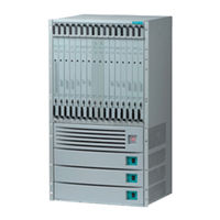
Lucent Technologies CBX 500 Installation Manual (232 pages)
Multiservice WAN Switch Hardware
Brand:
Lucent Technologies
| Category:
Switch
| Size: 1.69 MB
Table of Contents
Installation Guide
1
Maintenance Agreements
5
If the Product Is Damaged
5
If Problems Arise
6
Table of Contents
7
About this Guide
21
What You Need to Know
21
Reading Path
22
Documentation for New Modules
23
How to Use this Guide
23
What's New in this Guide
24
Conventions
25
Related Documents
26
Lucent
26
Ordering Printed Manuals Online
27
Customer Comments
27
Technical Support
27
Chapter 1 Overview
29
CBX 500 Product Description
29
CBX 500 Features
30
Hardware Component Descriptions
32
Figure 1-1. CBX 500 Switch
33
Figure 1-2. Relationship of SP and IOP Modules to Backplane
34
SP Modules
35
SP Features
35
SP Redundancy
35
IOP Modules (Iops)
36
Table 1-1. Supported Redundant SP Configurations
36
I/O and SP Adapters (Ioas and Spas)
37
CBX 500 Multiservice WAN Switch Hardware Installation Guide
37
Chapter 2 Specifications and Safety Warnings
39
Electronic/Electrical Requirements
40
Table 2-1. CBX 500 Electronic/Electrical Specifications
40
Physical Specifications
41
Table 2-2. CBX 500 Physical Specifications
41
Site Specifications
42
Operating Environment
42
Space Requirements
42
Table 2-3. CBX 500 Site Specifications
42
DC Power Supply Warnings
43
Safety Warnings
43
Signes Précurseurs de Sécurité
45
Achtung: Zusätzliche Sicherheitshinweise
46
Power Cord Requirements
47
Table 2-4. AC Power Cord Requirements
47
Selecting the Installation Site
49
Checking the Switch for Damage
50
Figure 3-1. CBX 500 Switch, Typical Shipping Configuration
50
Moving the Switch to the Installation Site
51
Unpacking the Switch
51
Unpacking the Accessory Kit
52
Verifying the Hardware Configuration
53
Before Handling Equipment
53
Checking the SP and IOP Modules
53
Figure 3-2. Front View of the CBX 500
54
Checking the SPA and IOA Modules
55
Figure 3-3. CBX 500 Showing SPA and IOA Module Locations
55
Checking the PCMCIA Configuration
56
Figure 3-4. PCMCIA Card Bay
56
What's Next
57
Installing the CBX 500 Switch
59
Before You Begin
59
Required Installation Tools and Equipment
60
Setting up the Switch
61
As a Free-Standing Switch
61
As a Rack-Mounted Switch
61
Installing 19-Inch MID-Mount Brackets
62
Figure 4-1. Installing 19-Inch MID-Mount Brackets
62
Installing 23-Inch MID-Mount Brackets
63
Figure 4-2. Installing 23-Inch MID-Mount Brackets
63
Installing 23-Inch Front-Mount Brackets
64
Figure 4-3. Installing 23-Inch Front-Mount Brackets
64
Installing the Switch into the Cabinet
66
Connecting Cables to the Switch
67
Network Management Connections
67
Figure 4-4. CBX 500 Switch Connected to NMS and Console Terminal
67
Chapter 3 Preparing for the Installation
49
Connecting the Console
68
Figure 4-5. Console Connection to CBX 500 Switch
68
Setting up the NMS
69
Connecting the NMS
69
Figure 4-6. Direct Ethernet Method
70
Figure 4-7. Indirect Ethernet Method
70
Figure 4-8. Management VC/PVC Method
71
Figure 4-9. Direct Ethernet Connection
71
Using Direct Ethernet
71
Figure 4-10. Indirect Ethernet Connection
72
Using Indirect Ethernet
72
Figure 4-11. Management VC/PVC Connection
73
Using Management VC/PVC
73
Connecting External Clock Inputs and Outputs
74
T1 Clock Connection
74
E1 Clock Connection
75
Figure 4-12. External Clock Inputs and Clock Outputs
75
Connecting External T1 Clock Source Inputs/Outputs
76
Connecting Alarm Relays
77
Connecting a Remote Alarm
78
Figure 4-13. Remote Alarm Terminals
78
G.703 Product Attachment Information
79
Table 4-1. Cable Specifications
79
Determining the Operating Status
81
Before You Begin
81
Status Leds
82
Switch Status Leds
82
Table 5-1. Switch Status Leds on SP Module
82
Module Status Leds
83
Port Alarm Leds
83
Table 5-2. Module Status Leds
83
Table 5-3. Port Alarm Leds
83
Redundancy Status Leds
84
Figure 5-1. Redundancy Status Leds
84
Table 5-4. IOP LED "Boot" States
84
PCMCIA Status Leds
85
Figure 5-2. PCMCIA Status Leds
85
Power Supply Status Leds
86
DC Power Failures - LED Status
86
Table 5-5. AC/DC Power-Supply Leds
86
Table 5-6. DC Power Failures - LED Status
86
Evaluating Power Loads for a Two-Power Supply Switch
87
Calculating Power Consumption
87
Table 5-7. Power Consumption by CBX 500 Components
88
Connecting Power to the Switch
89
Switches with AC Power Supplies
89
Figure 5-3. Connecting an AC Power Supply
90
Switches with DC Power Supplies
91
Figure 5-4. Connecting the -48 VDC Power Supplies
91
Powering up the Switch
94
What's Next
95
Installing and Removing Modules
97
Installation and Removal Precautions
98
Parts Repair
98
Static Protection
98
Electrical Energy Hazard
98
Switch Processor Module
99
CBX 500 Multiservice WAN Switch Hardware Installation Guide 4/5/03Ix
99
Removing an SP Module
99
Figure 6-1. Removing a Switch Processor (SP) Module
99
Installing an SP Module
101
Figure 6-2. Installing an SP Module
101
Installing a Redundant SP
102
Replacing the SPA Module
104
Figure 6-3. Removing the SPA Module
105
Figure 6-4. PCMCIA Card Bay
106
Removing and Replacing PCMCIA Cards
108
Figure 6-5. PCMCIA Card Slot Configuration
109
Installing or Replacing IOA Modules
110
Figure 6-6. Removing IOA Modules
111
Installing IOA Modules
112
Replacing IOA Modules
113
Installing and Replacing IOP Modules
114
IOP Slots According to SP Model Number
114
Figure 6-7. IOP Slots with SP 10
115
Redundant IOP Modules
116
Figure 6-9. Redundant-Pair Slots
116
Installing a New IOP Module
117
Installing a New IOA Module
117
Installing a New IOP Module
118
Replacing an IOP Module
119
Figure 6-10. Removing IOP Modules
119
Installing or Replacing Power Supplies
121
Figure 6-11. Power Distribution Unit for the AC Power Supply
122
Figure 6-12. Power Distribution Unit for a -48 VDC Power Supply
123
Removing a Power Supply
124
Installing a Power Supply
125
Figure 6-15. Connecting the -48 VDC Power Supply
127
Replacing the Cooling Fan Module
129
Removing the Cooling Fan Module
130
Installing the Cooling Fan Module
131
Installing or Replacing Air Filters
132
Figure 6-19. Installing or Replacing the Top Air Filter
133
Chapter 7 Troubleshooting
135
Power-Up Diagnostics for SP and IOP Modules
136
Table 7-1. DIP Switch Settings
136
Switch Troubleshooting
137
Table 7-2. Switch Troubleshooting
137
IOP Module Troubleshooting
138
Table 7-3. IOP Module Status
138
Power Supply Troubleshooting
139
Table 7-4. Power Supply Status
139
Appendix A IOP and IOA Module Specifications
142
8-Port T1 and E1 IOP Modules
142
Specifications
142
Physical Dimensions
142
Power Requirements
142
Agency Approvals
142
Table A-1. 8-Port T1 and E1 IOP/IOA Physical Dimensions
142
Temperature Range
143
Physical Interfaces
143
Physical Connectors (T1
143
Status Indicators
144
Port Alarm Indicators
144
Figure A-1. T1/E1 IOP and IOA Modules
145
32-Port Channelized T1/E1 FR/IP IOM
146
Specifications
146
Physical Dimensions
146
Temperature Range
146
Agency Approvals
146
Interface Standards
147
Other Standards
147
Physical Interfaces
147
Physical Connectors
147
Cable Requirements
148
Framing
148
Clocking Options
148
Module LED Status
149
Table A-2. Module LED Status Indicators
149
Table A-3. Port Alarm Status Indicators
149
Figure A-2. 32-Port Channelized T1/E1 FR/IP IOP and IOA Modules
150
8-Port DS3 and E3 ATM UNI IOP Modules
151
Specifications
151
Physical Dimensions
151
Power Requirements
151
Table A-4. 8-Port DS3 and E3 ATM UNI IOP/IOA Physical Dimensions
151
Temperature Range
152
Agency Approvals
152
Interface Standards
152
Other Standards Supported - DS3
152
Other Standards Supported - E3
153
Physical Interfaces - DS3
153
Physical Interfaces - E3
153
Module Status Indicators
153
Port Alarm Indicators
154
Figure A-3. DS3/E3 IOP and IOA Modules
155
6-Port DS3 Frame/Ip IOP Module
156
Specifications
156
Physical Dimensions
156
Table A-5. 6-Port DS3 Frame/Ip IOP/IOA Physical Dimensions
156
Power Requirements
157
Temperature Range
157
Agency Approvals
157
Interface Standards
157
Other Standards
157
Physical Interfaces
157
Physical Connectors
157
Module Status Indicators
158
Port Alarm Indicators
158
Figure A-4. 6-Port DS3 Frame/Ip IOP and IOA Modules
159
4-Port Channelized DS3 Frame/Ip IOP Module
160
Specifications
160
Physical Dimensions
160
Power Requirements
160
Table A-6. 4-Port Channelized DS3 Frame/Ip IOP/IOA Physical Dimensions
160
Agency Approvals and Electromagnetic Emissions Certifications
161
Physical Interfaces
161
Physical Connectors
161
Interface Standards
161
Line Coding
162
Framing
162
Signal Levels
162
Table A-7. DS3 and DS1 Standards
162
Status Indicators
163
Table A-8. Module LED Status Indicators
163
Table A-9. Physical Port Status Indicators
163
Figure A-5. 4-Port Channelized DS3 Frame/Ip IOP and IOA Modules
164
4-Port ATM UNI OC-3C/Stm-1 IOP Module
165
Specifications
165
Physical Dimensions
165
Power Requirements
165
Table A-10. 4-Port ATM UNI Oc03C/Stm-1 IOP/IOA Physical Dimensions
165
Table A-11. Cable Specifications
167
Other OC-3C Standards
168
Figure A-6. OC-3C/Stm-1 IOP and IOA Modules
170
1-Port OC-12C/Stm-4 IOP Module
171
Specifications
171
Physical Dimensions
171
Power Requirements
171
Agency Approvals
171
Table A-12. 1-Port OC-12C/Stm-4 IOP/IOA Physical Dimensions
171
Temperature Range
172
Physical Interfaces
172
Signal Distance/Levels (Single-Mode Laser Optics
172
Nebs
172
Interface Standards
173
Other STM-4 Standards
173
Status Indicators
174
Port Alarm Indicators
174
Figure A-7. OC-12C/Stm-4 IOP and IOA Modules
175
4-Port Ethernet IOP Module
176
Specifications
176
Physical Dimensions
176
Power Requirements
176
Temperature Range
176
Table A-13. 4-Port Ethernet IOP/IOA Physical Dimensions
176
Physical Interfaces
177
Interface Standards
177
Management Standards
177
Nebs
177
Agency Approvals
177
Port Alarm Indicators
178
Figure A-8. 4-Port Ethernet IOP and IOA Modules
179
8-Port Subrate Module
180
Specifications
180
Physical Dimensions
180
Power Requirements
180
Temperature Range
180
Agency Approvals Electromagnetic Emissions Certifications
180
Interface Standards
181
Other Standards
181
Physical Interfaces
181
Physical Connectors
181
Line Coding
181
Framing
181
Signal Levels
181
Link Performance Monitoring
182
Miscellaneous Link Message Support
182
Module Status Indicators
182
Table A-14. Module LED Status Indicators
182
Clocking Options
182
Port Alarm Indicators
183
Table A-15. Port Alarm Status Indicators
183
Figure A-9. 8-Port Subrate DS3 FR/IP IOM Front and Back Panel
184
3-Port Channelized Inverse Multiplexing over ATM (IMA) Module
185
Specifications
185
Power Requirements
185
Temperature Range
185
Agency Approvals Electromagnetic Emissions Certifications
186
Interface Standards
186
DS1 Standards
187
Physical Interfaces
187
Line Coding
187
Signal Levels
187
Clocking Options
187
Link Performance Monitoring
188
Module LED Status
188
Port Alarm Status
188
Table A-16. Module LED Status Indicators
188
Figure A-10. 3-Port Channelized DS3/1 IMA IOM IOP and IOA Panel
189
Appendix B Cables and Pinout Assignments
191
RS-232 Shielded Null-Modem Cable
192
Figure B-1. RS-232 Shielded Null-Modem Cable
193
RS-232 Shielded Straight-Through Modem Cable
194
Figure B-2. RS-232 Shielded Straight-Through Modem Cable
195
RS-232 DB-9 to DB-25 Shielded Crossover Cable
196
Figure B-3. RS-232 DB-9 to DB-25 Shielded Crossover Cable
197
T1 Straight-Through Cable
198
T1 Crossover Cable
199
Media Independent Interface (MII
200
Appendix C Regulatory Information
203
Regulatory Standards Compliance (Pending
204
Canadian IC CS-03 Requirements
205
Avis D'industrie Canada
206
FCC Part 68 General Information
207
FCC and Telephone Company Procedures and Requirements
209
Radio Frequency Interference
209
VCCI Statement
210
BSMI Statement
210
If Problems Arise
211
Example Affidavit (United States
212
Figure D-1. Slot Assignments for IOM Redundancy
214
Appendix D Redundancy
215
SP Redundancy
215
Status Indicators
216
Redundancy Manager
217
Keep-Alive Monitoring
218
Checksum/Version Number Exchange
219
Tftp Support
219
NMS Support
220
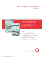
Lucent Technologies CBX 500 Brochure (4 pages)
CBX Multiservice Edge Switch Portfolio
Brand:
Lucent Technologies
| Category:
Switch
| Size: 0.41 MB
Advertisement
Lucent Technologies CBX 500 Specifications (2 pages)
3-Port Channelized DS3/1 ATM with IMA Input/Output (I/O) Module for the CBX 500 Multiservice Switch
Brand:
Lucent Technologies
| Category:
I/O Systems
| Size: 2.93 MB
Advertisement
Related Products
Lucent Technologies CBX 3500
Lucent Technologies CBX
Lucent Technologies Cajun A500
Lucent Technologies CentreVu Supervisor Version 8
Lucent Technologies CELLPIPE 20 series
Lucent Technologies CentreVu Release 3 Version 8 External Call History Interface
Lucent Technologies CentreVu Release 3 Version 8 Disk-Mirrored Systems
Lucent Technologies CentreVu Release 3 Version 8 Database Items and Calculations
Lucent Technologies CALLMASTER V
Lucent Technologies CentreVu
Lucent Technologies Categories
Telephone
Switch
Conference System
Software
Telephone System
More Lucent Technologies Manuals
Login
Sign In
OR
Sign in with Facebook
Sign in with Google
Upload manual
Upload from disk
Upload from URL