Lucent Technologies CBX 500 Installation Manual
Multiservice wan switch hardware
Hide thumbs
Also See for CBX 500:
- Specifications (2 pages) ,
- Brochure (4 pages) ,
- Configuration manual (888 pages)

Related Manuals for Lucent Technologies CBX 500


Summary of Contents for Lucent Technologies CBX 500
-
Page 1: Installation Guide
Beta Draft Confidential Beta Draft Confidential CBX 500 Multiservice WAN Switch Hardware Installation Guide Product Code: 80011 Revision 10 April 2003... - Page 2 Trademarks. NavisXtend and NavisCore are trademarks of Lucent Technologies. IP Navigator, Navis, CBX 500, GX 550, and B-STDX 9000 are registered trademarks of Lucent Technologies. Other trademarks and trade names mentioned in this document belong to their respective owners.
- Page 3 Beta Draft Confidential LUCENT TECHNOLOGIES LIMITED WARRANTY ON HARDWARE Lucent Technologies warrants the CBX 500 against defects in materials and workmanship for a period of one year from the date of shipment. During the warranty period, Lucent will, at its option, repair, replace, or refund the purchase price of any defective product at no additional cost, provided you return it during the warranty period, transportation charges prepaid, to Lucent.
- Page 4 This device must withstand any interference received, including interference that may cause undesired operation. The CBX 500 has been tested and found to comply with the limits for a Class A digital device pursuant to Part 15 of the FCC Rules and Regulations. These limits are designed to provide reasonable protection against harmful interference when this equipment is operated in a commercial environment.
-
Page 5: Maintenance Agreements
Upon receipt of this information, Lucent will provide you with service instructions, or a Return Authorization Number and shipping information. All items returned under warranty must be shipped to the manufacturer with the charges prepaid. CBX 500 Multiservice WAN Switch Hardware Installation Guide 4/5/03v... -
Page 6: If Problems Arise
FCC. In the event that repairs are ever needed on this equipment, they should be performed by Lucent Technologies or an authorized Lucent representative. For information contact the Lucent TAC at 1-866-LUCENT8 (in the U.S.). For international telephone numbers see “Technical Support”... -
Page 7: Table Of Contents
CBX 500 Product Description ...................1-1 CBX 500 Features ......................1-2 Hardware Component Descriptions ................1-4 SP Modules......................1-7 SP Features....................1-7 SP Redundancy .....................1-7 IOP Modules (IOPs) ....................1-8 I/O and SP Adapters (IOAs and SPAs) ...............1-9 CBX 500 Multiservice WAN Switch Hardware Installation Guide... - Page 8 Installing 19-inch Mid-Mount Brackets ............4-4 Installing 23-inch Mid-Mount Brackets ............4-5 Installing 23-inch Front-Mount Brackets ............. 4-6 Installing the Switch into the Cabinet............4-8 Connecting Cables to the Switch................4-9 Network Management Connections..............4-9 viii4/5/03 CBX 500 Multiservice WAN Switch Hardware Installation Guide...
- Page 9 Switches with DC Power Supplies ..............5-11 Powering Up the Switch...................5-14 What’s Next?......................5-15 Chapter 6 Installing and Removing Modules Installation and Removal Precautions................6-2 Parts Repair......................6-2 Static Protection....................6-2 Electrical Energy Hazard..................6-2 Switch Processor Module...................6-3 CBX 500 Multiservice WAN Switch Hardware Installation Guide 4/5/03ix...
- Page 10 8-port T1 and E1 IOP Modules ................A-2 Specifications ..................... A-2 Physical Dimensions..................A-2 Power Requirements..................A-2 Agency Approvals ..................A-2 Temperature Range..................A-3 Physical Interfaces..................A-3 Physical Connectors (T1) ................A-3 x4/5/03 CBX 500 Multiservice WAN Switch Hardware Installation Guide...
- Page 11 Physical Interfaces - DS3................A-13 Physical Interfaces - E3................A-13 Module Status Indicators ................A-13 Port Alarm Indicators.................A-14 6-port DS3 Frame/IP IOP Module ................A-16 Specifications....................A-16 Physical Dimensions ..................A-16 Power Requirements ..................A-17 Temperature Range ..................A-17 CBX 500 Multiservice WAN Switch Hardware Installation Guide 4/5/03xi...
- Page 12 Cable Specifications (STM-1 Electrical)..........A-27 Signal Distance/Levels (Single-mode Laser Optics)......... A-27 Signal Distance/Levels (Multimode LED Optics)........A-27 Other OC-3c Standards................A-28 Other STM-1 Standards................A-28 Status Indicators ..................A-28 Port Alarm Indicators ................A-29 xii4/5/03 CBX 500 Multiservice WAN Switch Hardware Installation Guide...
- Page 13 8-port Subrate Module ....................A-40 Specifications....................A-40 Physical Dimensions ..................A-40 Power Requirements ..................A-40 Temperature Range ..................A-40 Agency Approvals Electromagnetic Emissions Certifications ....A-40 Interface Standards..................A-41 Other Standards..................A-41 Physical Interfaces ..................A-41 Physical Connectors...................A-41 Line Coding....................A-41 CBX 500 Multiservice WAN Switch Hardware Installation Guide 4/5/03xiii...
- Page 14 T1 Crossover Cable (DB-15)..................B-9 Media Independent Interface (MII) ................ B-10 Appendix C Regulatory Information Regulatory Standards Compliance (Pending)............C-2 Canadian IC CS-03 Requirements................C-3 Avis D’Industrie Canada..................C-4 FCC Part 68 General Information................C-5 xiv4/5/03 CBX 500 Multiservice WAN Switch Hardware Installation Guide...
- Page 15 Example Affidavit (United States)................C-10 Appendix D Redundancy IOM Redundancy ......................D-1 SP Redundancy ......................D-3 Status Indicators ......................D-4 Redundancy Manager....................D-5 Keep-Alive Monitoring ..................D-6 TFTP Support .....................D-7 Checksum/Version Number Exchange...............D-7 NMS Support......................D-8 Acronyms Index CBX 500 Multiservice WAN Switch Hardware Installation Guide 4/5/03xv...
- Page 16 Installing 23-inch Mid-Mount Brackets ......... 4-5 Figure 4-3. Installing 23-inch Front-Mount Brackets ........4-6 Figure 4-4. CBX 500 Switch Connected to NMS and Console Terminal ..4-9 Figure 4-5. Console Connection to CBX 500 Switch ........4-10 Figure 4-6. Direct Ethernet Method ..............4-12 Figure 4-7.
- Page 17 T1 Crossover Cable Diagram............B-9 Figure D-1. Slot Assignments for IOM Redundancy ........D-2 Figure D-2. SP Slots in a CBX 500 Switch............D-3 Figure D-3. Redundancy Status LEDs .............. D-4 CBX 500 Multiservice WAN Switch Hardware Installation Guide 4/5/03xvii...
- Page 18 4-port Ethernet IOP/IOA Physical Dimensions ......A-36 Table A-14. Module LED Status Indicators ............ A-42 Table A-15. Port Alarm Status Indicators ............A-43 Table A-16. Module LED Status Indicators ............ A-48 xviii4/5/03 CBX 500 Multiservice WAN Switch Hardware Installation Guide...
- Page 19 T1 Straight-through Cable Pinouts (DB-15)........B-8 Table B-5. T1 Crossover Cable Pinouts (DB-15) ..........B-9 Table B-6. Media Independent Interface (MII) Pinouts ........ B-10 Table C-1. CBX 500 FCC Information............C-5 CBX 500 Multiservice WAN Switch Hardware Installation Guide 4/5/03xix...
- Page 20 Contents xx4/5/03 CBX 500 Multiservice WAN Switch Hardware Installation Guide...
-
Page 21: About This Guide
Beta Draft Confidential About This Guide The CBX 500 Hardware Installation Guide describes how to install and set up the ® CBX 500 switch hardware, replace hardware modules, and interpret LED status indicators. This guide also provides basic troubleshooting solutions for potential hardware-related problems. -
Page 22: Reading Path
Beta Draft Confidential About This Guide Reading Path Use the following guides to install and manage the CBX 500 switch: This guide describes how to install and set up the CBX 500 switch hardware, replace hardware modules, and interpret LED status indicators. -
Page 23: Documentation For New Modules
Chapter 2 Product specifications for the CBX 500 hardware, including environmental and electrical considerations. This chapter also lists the Safety Warnings related to the use of the CBX 500 hardware. Chapter 3 Installation prerequisites, such as unpacking the unit, taking inventory, and gathering installation items and equipment. -
Page 24: What's New In This Guide
User’s Guide into this Guide. Added a note to indicate that air filters must page 6-36 be vacuumed or replaced once a month to prevent heat from building up inside the chassis. xxiv4/5/03 CBX 500 Multiservice WAN Switch Hardware Installation Guide... -
Page 25: Conventions
Warning – Warnings notify the reader to proceed carefully to avoid hazards due to electrical shock that may arise from dangerous voltages. Warning – Electrostatic Discharge (ESD) Susceptibility warnings indicate that the following procedures may make the device susceptible to electrostatic charge. CBX 500 Multiservice WAN Switch Hardware Installation Guide 4/5/03xxv... -
Page 26: Related Documents
B-STDX, CBX, and GX Switch Diagnostics User’s Guide (Product Code: 80192) All manuals for the Core Switching Division and the Master Glossary are available on the Core Switching Division Technical Publications Documentation Library CD-ROM (Product Code: 80025). xxvi4/5/03 CBX 500 Multiservice WAN Switch Hardware Installation Guide... -
Page 27: Ordering Printed Manuals Online
The Lucent Technical Assistance Center (TAC) is available to assist you with any problems encountered while using this Lucent product. Log on to our Customer Support web site to obtain telephone numbers for the Lucent TAC in your region: http://www.lucent.com/support CBX 500 Multiservice WAN Switch Hardware Installation Guide 4/5/03xxvii... - Page 28 Beta Draft Confidential About This Guide xxviii4/5/03 CBX 500 Multiservice WAN Switch Hardware Installation Guide...
-
Page 29: Chapter 1 Overview
Beta Draft Confidential Overview This chapter is an overview of the CBX 500 multiservice switch, and includes the following topics: • CBX 500 Product Description • CBX 500 Features • Hardware Component Descriptions CBX 500 Product Description The CBX 500 is a multiservice, high-capacity ATM switch (5 Gbps) that supports ATM, Frame Relay, and IP switching at DS1/E1 through OC-12/STM-4 rates. -
Page 30: Cbx 500 Features
Beta Draft Confidential Overview CBX 500 Features CBX 500 Features The multiservice CBX 500 switch provides or supports the following features: • Multiprocessor and custom silicon design for highest performance and throughput • Quad-plane switch architecture with 128K cell buffers to ensure the highest level of data integrity •... - Page 31 Interim Link Management Interface (ILMI) and address registration on each port • Three system-timing modes: recovered, external, or internal • Four transmit timing and synchronization modes: loop, recovered, external, or internal CBX 500 Multiservice WAN Switch Hardware Installation Guide 4/5/031-3...
-
Page 32: Hardware Component Descriptions
Beta Draft Confidential Overview Hardware Component Descriptions Hardware Component Descriptions The CBX 500 has the following hardware components: • Switch processors (SPs) • Switch processor adapters (SPAs) • Input/output processors (IOPs) • Input/output adapters (IOAs) • Power supplies • Cooling fans •... -
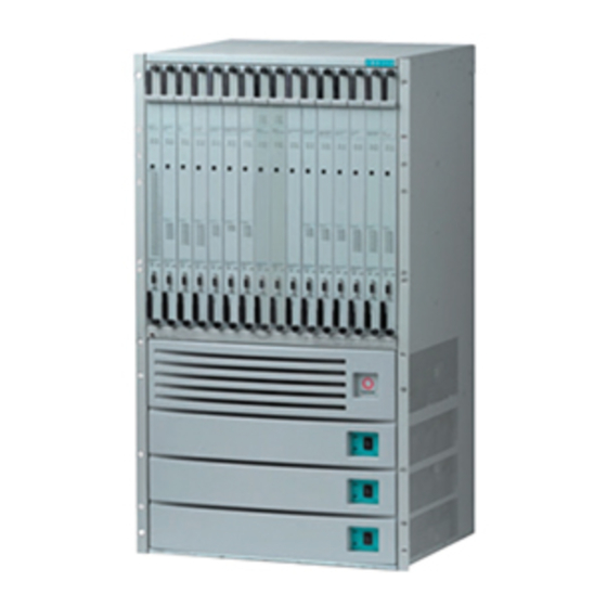
Page 33: Figure 1-1. Cbx 500 Switch
(SPA). The IOAs and SPA contain the connections for network cables and provide a hardware bridge between the physical network and the IOPs. CBX 500 Multiservice WAN Switch Hardware Installation Guide 4/5/031-5... -
Page 34: Figure 1-2. Relationship Of Sp And Iop Modules To Backplane
SP/SPA and IOP/IOA pair connect directly to each other. SPA or IOA SP or IOP Modules Modules Chassis Backplane Chassis Front with Bus Connectors Rear Switch Chassis Figure 1-2. Relationship of SP and IOP Modules to Backplane 1-64/5/03 CBX 500 Multiservice WAN Switch Hardware Installation Guide... -
Page 35: Sp Modules
Overview Hardware Component Descriptions SP Modules The switch processor (SP) provides background management and static networking functions for the IOP modules. CBX 500 SPs are available in four models: • Model 10 supports throughputs up to 2.5 Gbps • Models 20, 30, and 40 support throughputs up to 5 Gbps SP Features •... -
Page 36: Iop Modules (Iops)
SPs, via a separate backplane connection. All IOP modules are supported on SP Models 10, 20, 30, and 40. When upgrading (or downgrading) your switch, you do not have to replace the IOP modules. 1-84/5/03 CBX 500 Multiservice WAN Switch Hardware Installation Guide... -
Page 37: I/O And Sp Adapters (Ioas And Spas)
The SPA has a covered bay that houses the Ethernet and IDE hard drive PCMCIA card pair for each SP. The SPA also has timing and alarm connections. IOA configurations vary, depending on the specific module they support. CBX 500 Multiservice WAN Switch Hardware Installation Guide 4/5/031-9... - Page 38 Beta Draft Confidential Overview Hardware Component Descriptions 1-104/5/03 CBX 500 Multiservice WAN Switch Hardware Installation Guide...
-
Page 39: Chapter 2 Specifications And Safety Warnings
This chapter describes the following specifications and safety warnings for the CBX 500 switch: • Electronic/Electrical Requirements • Physical Specifications • Site Specifications • DC Power Supply Warnings • Safety Warnings • Power Cord Requirements CBX 500 Multiservice WAN Switch Hardware Installation Guide 4/5/032-1... -
Page 40: Electronic/Electrical Requirements
For either AC or DC input versions, the CBX 500 is powered by a minimum of two power supplies. For some applications, you can add a third power for redundancy, in... -
Page 41: Physical Specifications
19.0 in. (48.26 cm) wide x 33.25 in. (84.455 cm) high x Overall Switch Chassis Size 15 in. (38.1 cm) deep Switch Weight 200 lb max (fully configured) Depth size does not include calculations for cable spacing. CBX 500 Multiservice WAN Switch Hardware Installation Guide 4/5/032-3... -
Page 42: Site Specifications
-40°C to +65°C, 95% relative humidity Storage Altitude -1,000 to +30,000 ft (-305 to 9150 m) Space Requirements The CBX 500 hardware requires the following minimum clearances for the chassis: • 6 in. (15 cm) at the back panel (for cable routing) •... -
Page 43: Dc Power Supply Warnings
1. There are mechanical and electrical shock hazards present throughout the system if one or more of the modules is removed. There are no operator serviceable components. Only qualified personnel are allowed to service the unit. CBX 500 Multiservice WAN Switch Hardware Installation Guide 4/5/032-5... - Page 44 Warning – This unit has more than one power supply cord. To avoid electrical shock, disconnect the appropriate power supply cord prior to servicing. 2-64/5/03 CBX 500 Multiservice WAN Switch Hardware Installation Guide...
-
Page 45: Signes Précurseurs De Sécurité
à l'arrière de l'appareil. Warning – Cet appareil comporte plus d'un cordon d'alimentation. Afin de prévenir les chocs électriques débrancher le cordon d'alimentation approprié avant le dépannage. CBX 500 Multiservice WAN Switch Hardware Installation Guide 4/5/032-7... -
Page 46: Achtung: Zusätzliche Sicherheitshinweise
Möglichkeit das Netzteil ganz abzuschalten ist die entsprechende Zuleitung an der Rückseite des Gehäuses herauszuziehen. Warning – Achtung: Dieses Gerät hat mehr als eine Zuleitung. Um einen elektrischen Strom-schlag zu vermeiden muß die entsprechende Strom-Zuleitung vor der Wartung vomNetz getrenntwerden. 2-84/5/03 CBX 500 Multiservice WAN Switch Hardware Installation Guide... -
Page 47: Power Cord Requirements
Specifications and Safety Warnings Power Cord Requirements Power Cord Requirements The CBX 500 power cord is connected via a three-prong plug that grounds the switch and polarizes the connection. The ground connector must be grounded properly. Table 2-4 lists the country requirements for the plug types and their ratings. - Page 48 Beta Draft Confidential Specifications and Safety Warnings Power Cord Requirements 2-104/5/03 CBX 500 Multiservice WAN Switch Hardware Installation Guide...
-
Page 49: Preparing For The Installation
• Verifying the Hardware Configuration Selecting the Installation Site Before you choose a setup location for the CBX 500 switch, read and follow the site and electrical requirements defined in Chapter When selecting the setup location, you must ensure that the switch has adequate ventilation and space for current and future cabling requirements. -
Page 50: Checking The Switch For Damage
Checking the Switch for Damage Checking the Switch for Damage The CBX 500 is delivered in a protective shipping carton. The switch is shipped with all the ordered modules installed. The switch chassis is attached to a wooden pallet with screws and L-brackets (see Figure 3-1). -
Page 51: Moving The Switch To The Installation Site
2. Check the contents of the carton against the items listed on the packing slip. 3. Using a #2 Phillips-head screwdriver, remove the screws from the L-brackets on the delivery pallet (see Figure 3-1 on page 3-2). 4. Carefully remove the switch from the pallet. CBX 500 Multiservice WAN Switch Hardware Installation Guide 4/5/033-3... -
Page 52: Unpacking The Accessory Kit
The items in the accessory kit vary with each order. Unpack the accessory kit and check the contents against the items listed on the packing slip. The following required items are shipped with each CBX 500 order: • RS-232 shielded straight-through modem cable, M-F, 15 ft. (4.575 m) •... -
Page 53: Verifying The Hardware Configuration
Checking the SP and IOP Modules The CBX 500 switch has a backplane design that enables the SP and IOP modules in the front of the switch to connect to the SPAs and IOAs in the back of the switch. -
Page 54: Figure 3-2. Front View Of The Cbx 500
Front Bezel Figure 3-2. Front View of the CBX 500 Slots 1 and 2 are reserved for the SP modules; they cannot be used for IOP modules. Slot 1 contains the main SP module and Slot 2 may contain the optional redundant SP module. -
Page 55: Checking The Spa And Ioa Modules
SPA Module (Slots 1 & 2) Figure 3-3. CBX 500 Showing SPA and IOA Module Locations The SP adapter (SPA) and I/O adapter (IOA) modules are installed in the back of the switch. The SPA always occupies two slots (Slots 1 and 2), even if only one SP module is installed. -
Page 56: Checking The Pcmcia Configuration
This enables you to use the standard Ethernet connector on the SPA when you connect the switch to the console terminal or NMS. The SPA is shipped with the appropriate Ethernet and hard disk drive cards installed. 3-84/5/03 CBX 500 Multiservice WAN Switch Hardware Installation Guide... -
Page 57: What's Next
Preparing for the Installation What’s Next? What’s Next? When you finish unpacking and taking inventory of the CBX 500 hardware and accessory kit and have checked the installed modules, you can install the switch. Proceed to Chapter 4, “Installing the CBX 500 Switch.”... - Page 58 Beta Draft Confidential Preparing for the Installation What’s Next? 3-104/5/03 CBX 500 Multiservice WAN Switch Hardware Installation Guide...
-
Page 59: Installing The Cbx 500 Switch
Beta Draft Confidential Installing the CBX 500 Switch This chapter describes, in the following topics, how to set up and install the CBX 500 switch: • Required Installation Tools and Equipment • Setting Up the Switch • Connecting Cables to the Switch •... -
Page 60: Required Installation Tools And Equipment
Installing the CBX 500 Switch Required Installation Tools and Equipment Required Installation Tools and Equipment To install the CBX 500 hardware, you need the following tools and equipment: • An NMS or console terminal connection to the SP’s network management port to download installation scripts to the switch. -
Page 61: Setting Up The Switch
You can order these brackets from Lucent. For a current product code/price list, contact your Lucent account manager. Caution – The weight and position of the CBX 500 switch within the cabinet may make the cabinet top-heavy or unstable. You must anchor the cabinet securely before installing the switch. -
Page 62: Installing 19-Inch Mid-Mount Brackets
3. Repeat Steps 1 and 2 to install the second mid-mount bracket onto the other side of the switch. Caution – Failure to use the proper screws may damage the switch. 4-44/5/03 CBX 500 Multiservice WAN Switch Hardware Installation Guide... -
Page 63: Installing 23-Inch Mid-Mount Brackets
2. Using a #2 Phillips-head screwdriver, install the seven #10-32 x .25 truss-head screws and #10 external tooth lock washers that came with the brackets through the mid-mount bracket holes into the switch. Use a maximum of 6 to 8 inch-pounds of torque. CBX 500 Multiservice WAN Switch Hardware Installation Guide 4/5/034-5... -
Page 64: Installing 23-Inch Front-Mount Brackets
23-inch front-mount brackets onto the switch. Front-Mount Brackets 6 Screws (#10-32 x .25) 6 #10 Ext. Tooth Lock Washers 6 Screws (#10-32 x .25) 6 #10 Ext. Tooth Lock Washers Figure 4-3. Installing 23-inch Front-Mount Brackets 4-64/5/03 CBX 500 Multiservice WAN Switch Hardware Installation Guide... - Page 65 3. Repeat Steps 1 and 2 to install the second front-mount bracket onto the other side of the switch. Caution – Failure to use the proper screws may damage the switch. CBX 500 Multiservice WAN Switch Hardware Installation Guide 4/5/034-7...
-
Page 66: Installing The Switch Into The Cabinet
Note – Upon completion of the assembly of the chassis to the equipment rack, you may have some remaining screws, depending on the mounting configuration selected. This extra hardware can be discarded, if desired. 4-84/5/03 CBX 500 Multiservice WAN Switch Hardware Installation Guide... -
Page 67: Connecting Cables To The Switch
“virtual port” that enables the NMS to manage the switch through a single router or through an ATM network interface card (NIC) UNI-DCE connection. Figure 4-4 shows the CBX 500 switch connected to an NMS and console terminal. ASCII/VT100 Network Management... -
Page 68: Connecting The Console
Management Port To Console Serial Port Figure 4-5. Console Connection to CBX 500 Switch To connect the console terminal to the switch: • If the console is a PC, connect the DB-25 end of the RS-232 DB-9 to DB-25 Shielded Crossover cable to the network management port on the SPA. Then connect the DB-9 end of the RS-232 DB-9 to DB-25 Shielded Crossover cable to the serial port on the PC. -
Page 69: Setting Up The Nms
NMS to the switch, as described in the next section. Connecting the NMS You can connect the CBX 500 switch to the NMS, using the following methods: Direct Ethernet — Connects the switch and NMS when they are on the same LAN. -
Page 70: Figure 4-6. Direct Ethernet Method
Lucent network as a backup. Figure 4-6 through Figure 4-8 show the types of NMS-connection methods. Ethernet Port Figure 4-6. Direct Ethernet Method Ethernet Router Port Figure 4-7. Indirect Ethernet Method 4-124/5/03 CBX 500 Multiservice WAN Switch Hardware Installation Guide... -
Page 71: Using Direct Ethernet
Figure 4-8. Management VC/PVC Method Using Direct Ethernet Figure 4-9 shows how to make a direct Ethernet connection from the switch to the NMS. Ethernet Port Ethernet Port Figure 4-9. Direct Ethernet Connection CBX 500 Multiservice WAN Switch Hardware Installation Guide 4/5/034-13... -
Page 72: Using Indirect Ethernet
3. Connect the switch’s Ethernet port to a remote LAN that has router connectivity to the LAN on which the NMS resides. 4. Ensure that the Ethernet transceivers are connected properly to the network. 4-144/5/03 CBX 500 Multiservice WAN Switch Hardware Installation Guide... -
Page 73: Using Management Vc/Pvc
(local switch) or a management PVC connection (remote switch). 3. Configure the switch to route management traffic through the designated management VC/PVC connection. 4. Configure the router or ATM NIC with a static route to the Lucent network. CBX 500 Multiservice WAN Switch Hardware Installation Guide 4/5/034-15... -
Page 74: Connecting External Clock Inputs And Outputs
The SPA panel on the back of the switch contains three sets of wire-wrap pins for connecting the following: • An external T1 clock input • A redundant external T1 clock input • A T1 clock output 4-164/5/03 CBX 500 Multiservice WAN Switch Hardware Installation Guide... -
Page 75: E1 Clock Connection
SPA module. T1 Clock Inputs E1 Clock Inputs T1 Clock Output E1 Clock Output Figure 4-12. External Clock Inputs and Clock Outputs CBX 500 Multiservice WAN Switch Hardware Installation Guide 4/5/034-17... -
Page 76: Connecting External T1 Clock Source Inputs/Outputs
5. Reinstall the protective cover onto the wire-wrap pins. To connect an external E1 clock-source input or clock output, connect a 75-ohm cable with a BNC connector to the appropriate BNC port on the SPA module. 4-184/5/03 CBX 500 Multiservice WAN Switch Hardware Installation Guide... -
Page 77: Connecting Alarm Relays
– critical switch error condition – major switch error condition – minor switch error condition • Power (connects to power relay) – major switch error condition – minor switch error condition CBX 500 Multiservice WAN Switch Hardware Installation Guide 4/5/034-19... -
Page 78: Connecting A Remote Alarm
4. Insert the wire leads into the appropriate positive terminal connector and its return. 5. Using a 1/8-in. flathead screwdriver, tighten the screws on the positive and return terminals to secure the leads. 4-204/5/03 CBX 500 Multiservice WAN Switch Hardware Installation Guide... -
Page 79: G.703 Product Attachment Information
CBX 500 equipment. Table 4-1. Cable Specifications Interface Number DC Res. Nom. Nom. Max. Ω /km Type Twisted Capacitance Shield Length Ω Pairs pf/m G.703 - 75 Ω 49.2 66.7 120 m CBX 500 Multiservice WAN Switch Hardware Installation Guide 4/5/034-21... - Page 80 Beta Draft Confidential Installing the CBX 500 Switch G.703 Product Attachment Information 4-224/5/03 CBX 500 Multiservice WAN Switch Hardware Installation Guide...
-
Page 81: Determining The Operating Status
4. Connect the NMS to the switch (see page 4-11). 5. (Optional) Connect the external clock source inputs and outputs (see page 4-16). 6. (Optional) Connect the remote alarms (see page 4-20). CBX 500 Multiservice WAN Switch Hardware Installation Guide 4/5/035-1... -
Page 82: Status Leds
Determining the Operating Status Status LEDs Status LEDs The status LEDs on the CBX 500’s modules indicate the operating status of the switch and of each module. You can monitor these LEDs locally on the switch, or remotely through the NMS. -
Page 83: Module Status Leds
A downstream equipment failure has been detected on the (also called a Blue Alarm) circuit for the indicated port. Red Alarm ON A loss of signal has occurred on the port. CBX 500 Multiservice WAN Switch Hardware Installation Guide 4/5/035-3... -
Page 84: Redundancy Status Leds
Redundant Pair of Modules Non-Redundant Pair of Modules = OFF Redundancy Redundancy Redundancy Redundancy = ON Status Status Status Status Active Standby = BLINKING Module Module Figure 5-1. Redundancy Status LEDs 5-44/5/03 CBX 500 Multiservice WAN Switch Hardware Installation Guide... -
Page 85: Pcmcia Status Leds
Status LEDs Figure 5-2. PCMCIA Status LEDs Caution – If a PCMCIA card’s LED is on (indicating an error condition), you must power down the switch before removing the PCMCIA card. CBX 500 Multiservice WAN Switch Hardware Installation Guide 4/5/035-5... -
Page 86: Power Supply Status Leds
Green LED Blinking Pattern Indicates Power Failure on Three seconds ON, one second OFF DC Input A Three seconds ON, one second OFF; then one DC Input B second ON and one second OFF 5-64/5/03 CBX 500 Multiservice WAN Switch Hardware Installation Guide... -
Page 87: Evaluating Power Loads For A Two-Power Supply Switch
I/O modules before you connect power to the switch. The CBX 500’s 120-VAC chassis power supplies deliver 1050 watts of +5V power. Depending on the switch configuration and the power supplies, the total I/O module capacity may be limited if a single-chassis power supply is used. -
Page 88: Table 5-7. Power Consumption By Cbx 500 Components
Evaluating Power Loads for a Two-Power Supply Switch • CBX 500 IOPs have a maximum power consumption limit of 100 watts per slot. Using this number, you can calculate the worst-case power consumption on the switch backplane, as follows: 14 x 100 (IOMs) + 260 (SPs) + 75 (fans) = 1735 watts.To obtain the input power, divide this number by the power supply... -
Page 89: Connecting Power To The Switch
Fans Connecting Power to the Switch The CBX 500 is powered by either two AC or two DC power supplies. You can also install a third power supply for redundancy, to ensure continuous power in the event of a circuit or power-supply failure. -
Page 90: Figure 5-3. Connecting An Ac Power Supply
Determining the Operating Status Connecting Power to the Switch Cable Strain Relief Clamps Redundant Power Supply Receptacle Secondary Power Supply Primary Receptacle Power Supply Receptacle Figure 5-3. Connecting an AC Power Supply 5-104/5/03 CBX 500 Multiservice WAN Switch Hardware Installation Guide... -
Page 91: Switches With Dc Power Supplies
Connecting Power to the Switch Switches with DC Power Supplies To connect the switch’s DC power supplies to a power source: 1. Verify that the correct power source is available for the CBX 500 power supplies. (See Chapter 2, “Specifications and Safety Warnings,”... - Page 92 (see Figure 5-4 on page 5-11). Note – It is recommended that, to provide a single-point ground connection, only one of the chassis grounds should be connected to earth ground ( 5-124/5/03 CBX 500 Multiservice WAN Switch Hardware Installation Guide...
- Page 93 4. Plug the other end of the main power cords into the DC power source for the switch. To ensure continuous power in the event of a power source failure, you should plug each power cord into different DC power sources, if possible. CBX 500 Multiservice WAN Switch Hardware Installation Guide 4/5/035-13...
-
Page 94: Powering Up The Switch
LED remains solid green, as does the switch’s Good LED located at the top of the module. Also, the Good LED on each configured IOP module comes on solid green. (The Good LED on any unconfigured IOP module blinks slowly.) 5-144/5/03 CBX 500 Multiservice WAN Switch Hardware Installation Guide... -
Page 95: What's Next
Download the software configuration to the switch; see the B-STDX, CBX, and GX Getting Started User’s Guide for instructions. • Install and configure the NMS software; see the B-STDX, CBX, and GX Network Management Station Installation Guide for instructions. CBX 500 Multiservice WAN Switch Hardware Installation Guide 4/5/035-15... - Page 96 Beta Draft Confidential Determining the Operating Status What’s Next? 5-164/5/03 CBX 500 Multiservice WAN Switch Hardware Installation Guide...
-
Page 97: Installing And Removing Modules
Beta Draft Confidential Installing and Removing Modules The chapter provides information about installing and removing CBX 500 modules, in the following topics: • Installation and Removal Precautions • Switch Processor Module • Replacing the SPA Module • Removing and Replacing PCMCIA Cards •... -
Page 98: Installation And Removal Precautions
Installation and Removal Precautions Installation and Removal Precautions The CBX 500 switch design enables you to install, remove, and replace most modules by “hot-swapping” (that is, without powering down the switch). However, you may choose to power down the switch as a precaution if the switch is not currently operational. -
Page 99: Switch Processor Module
See the B-STDX, CBX, and GX Switch Module Configuration Guide for information about switching to a redundant card, using NavisCore. Removing an SP Module Figure 6-1. Removing a Switch Processor (SP) Module CBX 500 Multiservice WAN Switch Hardware Installation Guide 4/5/036-3... - Page 100 5. Lift the top and bottom card ejectors simultaneously to remove the module from the switch. 6. Carefully slide the SP module out of the chassis and place it into an antistatic container. 6-44/5/03 CBX 500 Multiservice WAN Switch Hardware Installation Guide...
-
Page 101: Installing An Sp Module
3. Slide the card ejector lock up. 4. Using a #2 Phillips-head screwdriver, tighten the two thumbscrews (using a maximum of 6 to 8 inch-pounds of torque). 5. If necessary, restore power to the switch. CBX 500 Multiservice WAN Switch Hardware Installation Guide 4/5/036-5... -
Page 102: Installing A Redundant Sp
6. Slide the card ejector lock up. 7. Using a #2 Phillips-head screwdriver, secure the module into the chassis by tightening the two thumbscrews (using a maximum of 6 to 8 inch-pounds of torque). 6-64/5/03 CBX 500 Multiservice WAN Switch Hardware Installation Guide... - Page 103 Note – If the original operating system (loaded at the factory before shipping the SP) becomes lost or corrupted, follow the instructions in the appropriate switch-code release note to download a new OS and configuration. CBX 500 Multiservice WAN Switch Hardware Installation Guide 4/5/036-7...
-
Page 104: Replacing The Spa Module
Slide the SP module out of the chassis about one inch (2.54 cm). 4. From the back of the switch, disconnect any external cables and wires from the existing SPA module. Tag the cables and wires for identification and reconnection. 6-84/5/03 CBX 500 Multiservice WAN Switch Hardware Installation Guide... -
Page 105: Figure 6-3. Removing The Spa Module
10. In the front of the switch, install the SP. Ensure that you push the ejector lock up and tighten the thumbscrews. 11. On the back of the switch, finish tightening the thumbscrews at the top and bottom of the SPA module. CBX 500 Multiservice WAN Switch Hardware Installation Guide 4/5/036-9... -
Page 106: Figure 6-4. Pcmcia Card Bay
Each SP has a pair of PCMCIA cards; the thinner one on the right is the Ethernet card. The hard drive is thicker than the Ethernet card and occupies the left slot. (There can be an Ethernet/hard drive pair for both SPs in the switch.) 6-104/5/03 CBX 500 Multiservice WAN Switch Hardware Installation Guide... - Page 107 17. Slide the PCMCIA cover back into position, and using a #2 Phillips-head screwdriver, tighten the screw at the top of the PCMCIA cover (using a maximum of 6 to 8 inch-pounds of torque). CBX 500 Multiservice WAN Switch Hardware Installation Guide 4/5/036-11...
-
Page 108: Removing And Replacing Pcmcia Cards
6. Push the square, flat black buttons at the bottom of each PCMCIA card to eject the cards. After the cards are removed, ensure that they are protected from static discharge. 6-124/5/03 CBX 500 Multiservice WAN Switch Hardware Installation Guide... -
Page 109: Figure 6-5. Pcmcia Card Slot Configuration
Note – At this time, if you want to replace the PCMCIA card on the other SP, wait 15-20 minutes after the SP is back online before performing another card switchover. This delay provides adequate time for the switch to synchronize its internal files. CBX 500 Multiservice WAN Switch Hardware Installation Guide 4/5/036-13... -
Page 110: Installing Or Replacing Ioa Modules
The IOA module has to be installed in the back of the switch before you can install the IOP module that it supports. Caution – Unlike previous CBX 500 modules, the 32-Port Channelized T1/E1 FR/IP IOM uses a new type of connector with closely-spaced pin alignments. You should carefully plug in and secure the IOA before connecting the input/output processor (IOP) module to it. -
Page 111: Figure 6-6. Removing Ioa Modules
Beta Draft Confidential Installing and Removing Modules Installing or Replacing IOA Modules Figure 6-6. Removing IOA Modules CBX 500 Multiservice WAN Switch Hardware Installation Guide 4/5/036-15... -
Page 112: Installing Ioa Modules
Installing or Replacing IOA Modules Installing IOA Modules Caution – Unlike previous CBX 500 modules, the 32-Port Channelized T1/E1 FR/IP IOM uses a new type of connector with closely-spaced pin alignments. You should carefully plug in and secure the IOA before connecting the input/output processor (IOP) module to it. -
Page 113: Replacing Ioa Modules
8. Insert the new or replacement IOA module into the back of the switch, aligning it with the card guides. CBX 500 Multiservice WAN Switch Hardware Installation Guide 4/5/036-17... -
Page 114: Installing And Replacing Iop Modules
14. Check the LEDs to verify the operational status of the cards. Installing and Replacing IOP Modules In the CBX 500 switch, the installation of IOP modules depends on the SP model type. IOP Slots According to SP Model Number You can install IOP modules in slots 7-9 and 10-12 (with an SP 10;... -
Page 115: Figure 6-7. Iop Slots With Sp 10
Figure 6-7. IOP Slots with SP 10 3 4 5 6 7 8 9 1 2 10 11 1213 14 15 16 Figure 6-8. IOP Slots with SP 20, 30, 40 CBX 500 Multiservice WAN Switch Hardware Installation Guide 4/5/036-19... -
Page 116: Redundant Iop Modules
3 4 5 6 7 8 9 1 2 10 11 1213 14 15 16 Figure 6-9. Redundant-Pair Slots Appendix D, “Redundancy” for more information about CBX 500 redundancy. 6-204/5/03 CBX 500 Multiservice WAN Switch Hardware Installation Guide... -
Page 117: Installing A New Iop Module
Warning – The following procedure may make the device susceptible to electrostatic charge. Caution – Unlike previous CBX 500 modules, the 32-Port Channelized T1/E1 FR/IP IOM uses a new type of connector with closely-spaced pin alignments. You should carefully plug in and secure the IOA before connecting the input/output processor (IOP) module to it. -
Page 118: Installing A New Iop Module
Warning – The following procedure may make the device susceptible to electrostatic charge. Caution – Unlike previous CBX 500 modules, the 32-Port Channelized T1/E1 FR/IP IOM uses a new type of connector with closely-spaced pin alignments. You should carefully plug in and secure the IOA before connecting the input/output processor (IOP) module to it. -
Page 119: Replacing An Iop Module
(via the NMS) before replacing the module. When an IOP is removed, all of its ports and circuits are terminated. Data loss may also occur on those circuits. Figure 6-10. Removing IOP Modules CBX 500 Multiservice WAN Switch Hardware Installation Guide 4/5/036-23... - Page 120 SP automatically downloads its current version of the boot code to the IOP card before downloading the application code. The IOP card may reboot several times before the download process completes. 6-244/5/03 CBX 500 Multiservice WAN Switch Hardware Installation Guide...
-
Page 121: Installing Or Replacing Power Supplies
Note – Before replacing the power supply, see the section,“DC Power Supply Warnings,” in Chapter 2. CBX 500 switches support both AC and DC power supplies. Figure 6-11 on page 6-26 shows the Power Distribution Unit for the AC power supply module. -
Page 122: Figure 6-11. Power Distribution Unit For The Ac Power Supply
Installing or Replacing Power Supplies Redundant Cable Strain Power Supply Relief Clamps Receptacle Secondary Power Supply Primary Receptacle Power Supply Receptacle Figure 6-11. Power Distribution Unit for the AC Power Supply 6-264/5/03 CBX 500 Multiservice WAN Switch Hardware Installation Guide... -
Page 123: Figure 6-12. Power Distribution Unit For A -48 Vdc Power Supply
Although the AC and DC power supply modules look different, the removal and replacement procedures are identical except for the power cord connection. Both AC and DC power supplies are removed from the front of the switch. CBX 500 Multiservice WAN Switch Hardware Installation Guide 4/5/036-27... -
Page 124: Removing A Power Supply
Figure 6-13. Removing the Power Supply Module 4. Grasp and lift the handle on the front of the power supply, then carefully pull the power supply out of the power supply bay. 6-284/5/03 CBX 500 Multiservice WAN Switch Hardware Installation Guide... -
Page 125: Installing A Power Supply
4. Tighten the two screws with a #2 Phillips-head screwdriver (using a maximum of 6 to 8 inch-pounds of torque). 5. Reconnect or reinstall the power cords, as described on the next page, for both AC and DC power cords. CBX 500 Multiservice WAN Switch Hardware Installation Guide 4/5/036-29... - Page 126 Locate the three #10 studs on the back of the power supply. c. Using a #2 Phillips-head screwdriver, remove the two screws that secure the protective cover over the studs. Then remove the protective cover. 6-304/5/03 CBX 500 Multiservice WAN Switch Hardware Installation Guide...
-
Page 127: Figure 6-15. Connecting The -48 Vdc Power Supply
(see Figure 5-4 Chapter 5). Note – It is recommended that, to provide a single-point ground connection, only one of the chassis grounds should be connected to earth ground ( CBX 500 Multiservice WAN Switch Hardware Installation Guide 4/5/036-31... - Page 128 Then push on both sides of the cover with the palms of your hands to snap the cover back into place. 6-324/5/03 CBX 500 Multiservice WAN Switch Hardware Installation Guide...
-
Page 129: Replacing The Cooling Fan Module
Before removing the cooling fan module from the switch, you must remove the fan module cover and fan access cover, as shown in Figure 6-16. Figure 6-16. Accessing the Cooling Fan Module CBX 500 Multiservice WAN Switch Hardware Installation Guide 4/5/036-33... -
Page 130: Removing The Cooling Fan Module
5. Carefully slide the fan tray out of the switch along the card guides, as shown in Figure 6-17. Figure 6-17. Removing the Cooling Fan Module 6-344/5/03 CBX 500 Multiservice WAN Switch Hardware Installation Guide... -
Page 131: Installing The Cooling Fan Module
Then push on both sides of the bezel with the palms of your hands to snap the cover into place, as shown in Figure 6-18. Figure 6-18. Installing the Cooling Fan Module CBX 500 Multiservice WAN Switch Hardware Installation Guide 4/5/036-35... -
Page 132: Installing Or Replacing Air Filters
Installing and Removing Modules Installing or Replacing Air Filters Installing or Replacing Air Filters There are two air filters that you can optionally order and install in the CBX 500 switch: • The top filter slides into the air intake area above the fan tray on the front of the chassis •... -
Page 133: Figure 6-19. Installing Or Replacing The Top Air Filter
7. Remove the cover plate’s top screw with a 1/4-in. Phillips-head screwdriver. 8. Carefully pull out the cover plate from the chassis (Figure 6-20). Figure 6-20. Installing or Replacing the Side Air Filter CBX 500 Multiservice WAN Switch Hardware Installation Guide 4/5/036-37... - Page 134 12. To replace the air filters, follow the steps to remove the old filters and reinstall new ones. 6-384/5/03 CBX 500 Multiservice WAN Switch Hardware Installation Guide...
-
Page 135: Chapter 7 Troubleshooting
If you suspect software problems, see the B-STDX, CBX, and GX Switch Diagnostics Guide. The status of the CBX 500 switch and its modules is indicated by status LEDs. For more information about the location and meaning of the LEDs, see Chapter 5, “Determining the Operating Status.”... -
Page 136: Power-Up Diagnostics For Sp And Iop Modules
SP polling mechanism suspects a failure in an IOP module slot, it reboots the card. If either position on the SP module DIP switch is in the OFF (left) position, the SP cannot reboot the cards. 7-24/5/03 CBX 500 Multiservice WAN Switch Hardware Installation Guide... -
Page 137: Switch Troubleshooting
The PCMCIA hard drive is Check the LEDs on the PCMCIA cards. not working or is inserted Reseat or replace the cards as needed. improperly. CBX 500 Multiservice WAN Switch Hardware Installation Guide 4/5/037-3... -
Page 138: Iop Module Troubleshooting
LED (green) condition on the IOP standby. See the B-STDX, CBX, and GX was on and is module. Switch Diagnostics Guide for now blinking. information about checking the Traps Alarm log. 7-44/5/03 CBX 500 Multiservice WAN Switch Hardware Installation Guide... -
Page 139: Power Supply Troubleshooting
Replace the power supply module. LED on a power experienced a partial failure, See the section, “Installing or Replacing supply. but is still operational. Power Supplies,” in Chapter 6 for instructions. CBX 500 Multiservice WAN Switch Hardware Installation Guide 4/5/037-5... - Page 140 Beta Draft Confidential Troubleshooting Power Supply Troubleshooting 7-64/5/03 CBX 500 Multiservice WAN Switch Hardware Installation Guide...
- Page 141 4-port Channelized DS3 Frame/IP IOP Module • 4-port ATM UNI OC-3c/STM-1 IOP Module • 1-port OC-12c/STM-4 IOP Module • 4-port Ethernet IOP Module • 8-port Subrate Module • 3-port Channelized Inverse Multiplexing over ATM (IMA) Module CBX 500 Multiservice WAN Switch Hardware Installation Guide 4/5/03A-1...
-
Page 142: 8-Port T1 And E1 Iop Modules
8-port T1 and E1 IOP Modules In the CBX 500 switch, the 8-port T1 and E1 IOP modules provide user connections at data rates of 1.544 Mbps (T1) or 2.048 Mbps (E1) on each of the eight ports. You can configure each port individually as a User-to-Network Interface (UNI). -
Page 143: Temperature Range
Jitter: meets or exceeds template defined in AT&T Publication 62411 T1 Interface Standards • ATM Forum UNI 3.0/3.1 • ANSI T1.102 • ANSI T1.107 • ANSI T1.231 • ANSI T1 403 • ITU G.804 • AT&T 62411 • AT&T 54016 CBX 500 Multiservice WAN Switch Hardware Installation Guide 4/5/03A-3... -
Page 144: Status Indicators
Red ON Loss of signal Red BLINKING Downstream equipment failure Figure A-1 on page A-5 shows the T1 IOP and IOA, the E1 IOP, and 75-ohm and 120-ohm E1 IOA modules. A-44/5/03 CBX 500 Multiservice WAN Switch Hardware Installation Guide... -
Page 145: Figure A-1. T1/E1 Iop And Ioa Modules
Diag Port E1 75-Ohm E1 120-Ohm Adpt. Mod. Adpt. Mod. Adpt. Mod. T1 IOP T1 IOA E1 IOP 75-ohm 120-ohm E1 IOA E1 IOA Figure A-1. T1/E1 IOP and IOA Modules CBX 500 Multiservice WAN Switch Hardware Installation Guide 4/5/03A-5... -
Page 146: 32-Port Channelized T1/E1 Fr/Ip Iom
The 32-Port Channelized T1/E1 Frame Relay/Internet Protocol (FR/IP) input/output module (IOM) for the CBX 500 switch provides 32 T1/E1 channelized physical ports on the input/output adapter (IOA). The CBX 500 switch supports a maximum of ten 32-Port Channelized T1/E1 FR/IP IOMs per chassis. -
Page 147: Interface Standards
E1 mode: 30 TS0 channels per physical port (960 logical ports per IOM, each at 64 Kbps) Physical Connectors • 32-Port Channelized T1 FR/IP I/O connector panel: RJ48, 100-ohm • 32-Port Channelized E1 FR/IP I/O connector panel: RJ48, 120-ohm CBX 500 Multiservice WAN Switch Hardware Installation Guide 4/5/03A-7... -
Page 148: Cable Requirements
TS16 enabled and CRC-4 enabled/disabled – TS16 disabled and CRC-4 enabled/disabled – Unstructured Clocking Options • Loop timing • Internal timing (better than Stratum 4 - +/- 20 PPM [parts per million]) A-84/5/03 CBX 500 Multiservice WAN Switch Hardware Installation Guide... -
Page 149: Module Led Status
Red LED lit Loss of frame or signal Red LED blinking Downstream equipment failure resulting in an alarm indication signal (AIS) Figure A-9 shows the 32-Port Channelized T1/E1 FR/IP IOP and IOA modules.. CBX 500 Multiservice WAN Switch Hardware Installation Guide 4/5/03A-9... -
Page 150: Figure A-2. 32-Port Channelized T1/E1 Fr/Ip Iop And Ioa Modules
Alarms Yel Red 17-24 17-24 25-32 25-32 Redundancy Status Diag Port Adpt. Mod. Adpt. Mod. IOA - T1 IOA - E1 Figure A-2. 32-Port Channelized T1/E1 FR/IP IOP and IOA Modules A-104/5/03 CBX 500 Multiservice WAN Switch Hardware Installation Guide... -
Page 151: 8-Port Ds3 And E3 Atm Uni Iop Modules
• OPTimum cell trunk The 16-slot CBX 500 switch provides a maximum of 112 DS3 or E3 ports per switch. The port buffers (8K each), combined with the 128K programmable cell buffers in the switch processor (SP) quad-plane architecture, provide the flexibility, performance, and data integrity required for high-speed networking. -
Page 152: Temperature Range
• ANSI T1.403 • ATM Forum UNI 3.0/3.1 • Bellcore TR-NWT 001112 • Bellcore TR-TSY-000499 • Bellcore TR-NWT-000820 • ITU G.804 • RFC 1407 • TR54014 (AT&T ACCUNET T45 and T45R) A-124/5/03 CBX 500 Multiservice WAN Switch Hardware Installation Guide... -
Page 153: Other Standards Supported - E3
Normal operation Failed ON Module failure Redundant ON Active module (that is, this module is online) Good and Failed LEDs OS software image currently being downloaded from the BLINKING simultaneously active SP CBX 500 Multiservice WAN Switch Hardware Installation Guide 4/5/03A-13... -
Page 154: Port Alarm Indicators
8-port DS3 and E3 ATM UNI IOP Modules Port Alarm Indicators LEDs: Yellow, Red LED State Status Yellow ON Downstream equipment sees loss of signal Red BLINKING Downstream equipment failure Red ON Loss of signal A-144/5/03 CBX 500 Multiservice WAN Switch Hardware Installation Guide... -
Page 155: Figure A-3. Ds3/E3 Iop And Ioa Modules
E3 Ports Good Good Failed Failed Alarms Alarms Yel Red Yel Red Redundancy Redundancy Status Status Diag Port Diag Port Adpt. Mod. Adpt. Mod. Figure A-3. DS3/E3 IOP and IOA Modules CBX 500 Multiservice WAN Switch Hardware Installation Guide 4/5/03A-15... -
Page 156: 6-Port Ds3 Frame/Ip Iop Module
6-port DS3 Frame/IP IOP Module 6-port DS3 Frame/IP IOP Module The 6-port DS3 Frame/IP module enables the CBX 500 to operate as a multiservice switch by providing IP routing for cell-based IP traffic, Frame Relay switching, and Frame Relay-to-ATM interworking. In addition, the module works with IP Services to provide routing for the entire CBX 500 switch through a local IP forwarding engine on the module. -
Page 157: Power Requirements
ANSI T1.102 Other Standards • Frame Relay Forum • RFC 1483 • RFC 1407 • Bellcore TR-NWT-000820 Physical Interfaces • 6 DS3 (44.736 Mbps) ports Physical Connectors • Dual 75-ohm BNC connector CBX 500 Multiservice WAN Switch Hardware Installation Guide 4/5/03A-17... -
Page 158: Module Status Indicators
Yellow ON Downstream equipment sees loss of signal Red BLINKING Downstream equipment failure Red ON Loss of signal Figure A-4 on page A-19 shows the DS3 Frame/IP IOP and IOA modules. A-184/5/03 CBX 500 Multiservice WAN Switch Hardware Installation Guide... -
Page 159: Figure A-4. 6-Port Ds3 Frame/Ip Iop And Ioa Modules
6-port DS3 Frame/IP IOP Module DS3 FR/IP Ports DS3 FR/IP Good Failed Alarms Yel Red Redundancy Status Diag. Port DS3 FR/IP Adpt. Mod. Figure A-4. 6-port DS3 Frame/IP IOP and IOA Modules CBX 500 Multiservice WAN Switch Hardware Installation Guide 4/5/03A-19... -
Page 160: 4-Port Channelized Ds3 Frame/Ip Iop Module
The 4-port channelized DS3 Frame/IP modules provide a channelized DS3 interface with up to 28 DS1 connections. You can individually configure each of the DS1 channels to provide any Frame Relay logical port function on the CBX 500 switch. The 4-port channelized DS3 Frame/IP module is available in two versions: •... -
Page 161: Agency Approvals And Electromagnetic Emissions Certifications
Dual 75-ohm BNC connectors (transmit/receive) per port Interface Standards • ANSI T1.102 • AT&T Publication 62415 • International ITU Standards Table A-7 on page A-22 lists the supported DS3 and DS1 standards. CBX 500 Multiservice WAN Switch Hardware Installation Guide 4/5/03A-21... -
Page 162: Line Coding
• Receive: Peak pulse amplitude from 0.2 to 0.85 volts • Transmit: Conform to ANSI T1.102 pulse template and amplitude (0.36 volts to 0.85 volts) for cable up to 450 feet A-224/5/03 CBX 500 Multiservice WAN Switch Hardware Installation Guide... -
Page 163: Status Indicators
Downstream equipment sees loss of signal resulting in a Remote Alarm Indication (RAI) Figure A-5 on page A-24 shows the 4-port channelized DS3 Frame/IP IOP and IOA modules. Both versions (DS3/1 and DS3/1/0) look the same. CBX 500 Multiservice WAN Switch Hardware Installation Guide 4/5/03A-23... -
Page 164: Figure A-5. 4-Port Channelized Ds3 Frame/Ip Iop And Ioa Modules
Chnlzd DS310 FR/IP IOP Chnlzd DS310 FR/IP IOP Good Failed Alarms Yel Red Redundancy Status Diag Port Chnlzd DS310 FR/IP Adpt. Mod. Figure A-5. 4-port Channelized DS3 Frame/IP IOP and IOA Modules A-244/5/03 CBX 500 Multiservice WAN Switch Hardware Installation Guide... -
Page 165: 4-Port Atm Uni Oc-3C/Stm-1 Iop Module
The OC-3c/STM-1 module has 24K cell buffers per port, enabling you to customize your network for specific traffic needs. The port buffers and the 128K cell buffers on the SP are based on the CBX 500 switch quad-plane architecture. Specifications Physical Dimensions Table A-10. - Page 166 • ANSI T1.106 Interface Standards (STM-1) • ITU G.703 (electrical) • ITU G.957 (optical) • ITU G.709 (optical) Physical Connectors • Subscriber Connector (SC) • BNC 75-ohm Coaxial Connectors (STM-1 electrical) A-264/5/03 CBX 500 Multiservice WAN Switch Hardware Installation Guide...
-
Page 167: Table A-11. Cable Specifications
RX Sensitivity: -10dBm, -34dBm – Nominal Wavelength: 1310 nm Signal Distance/Levels (Multimode LED Optics) • Up to 2 kilometers • 62.5/125 micron fiber • TX Power: -14dBm, -20dBm • RX Sensitivity: -14dBm, -29dBm CBX 500 Multiservice WAN Switch Hardware Installation Guide 4/5/03A-27... -
Page 168: Other Oc-3C Standards
Normal operation Failed ON Module failure Redundant ON Active module (that is, this module is online) Good and Failed LEDs OS software image currently being downloaded from BLINKING simultaneously the active SP A-284/5/03 CBX 500 Multiservice WAN Switch Hardware Installation Guide... - Page 169 Status Yellow ON Downstream equipment sees loss of signal Red BLINKING Downstream equipment failure Red ON Loss of signal Figure A-6 on page A-30 shows the OC-3c/STM-1 IOP and IOA modules. CBX 500 Multiservice WAN Switch Hardware Installation Guide 4/5/03A-29...
-
Page 170: Figure A-6. Oc-3C/Stm-1 Iop And Ioa Modules
PRODUCT PRODUCT PRODUCT STM-1 E OC-3c/STM-1 OC-3c/STM-1 OC-3c/STM-1 Adpt. Mod. SMMR SMLR Adpt. Mod. Adpt. Mod. Adpt. Mod. (Single-mode (Single-mode (Multimode) (Electrical) medium-reach) long-reach) Figure A-6. OC-3c/STM-1 IOP and IOA Modules A-304/5/03 CBX 500 Multiservice WAN Switch Hardware Installation Guide... -
Page 171: 1-Port Oc-12C/Stm-4 Iop Module
(UNI), an Interim Inter-switch Signalling Protocol (IISP) trunk, or a Lucent trunk. With the CBX 500’s 16-slot modular architecture, the CBX 500 can support up to 14 OC-12c/STM-4 ports per switch, with up to eight ports configured for full bandwidth. -
Page 172: Temperature Range
Attenuation: 10 dB to 24 dB – Nominal Wavelength: 1310 nm – Tx Power: between -3 and +2 dBm – Rx Sensitivity: -8 dBm (max.), -28 dBm (min.) NEBS • GR-63-CORE • GR-1089-CORE A-324/5/03 CBX 500 Multiservice WAN Switch Hardware Installation Guide... -
Page 173: Interface Standards
ITU G.707 • ITU G.708 • ITU G.709 • ITU G.783 • RFC SONET 1595 Far End Statistics • ATM Forum UNI 3.0/3.1 • ANSI T1.231 • Bellcore TR-NWT-001112 • Bellcore GR-253-CORE CBX 500 Multiservice WAN Switch Hardware Installation Guide 4/5/03A-33... -
Page 174: Status Indicators
Failed ON Indicates module failure Port Alarm Indicators LEDs: Yellow, Red LED State Status Yellow ON Downstream equipment sees loss of signal Red ON Loss of signal Red BLINKING Downstream equipment failure A-344/5/03 CBX 500 Multiservice WAN Switch Hardware Installation Guide... -
Page 175: Figure A-7. Oc-12C/Stm-4 Iop And Ioa Modules
Diag Port CLASS 1 CLASS 1 LASER CDRH PRODUCT LASER PRODUCT OC-12c/STM-4 OC-12c SMMR Adpt. Mod. SMLR Adpt. Mod. (single-mode long reach) (single-mode medium reach) Figure A-7. OC-12c/STM-4 IOP and IOA Modules CBX 500 Multiservice WAN Switch Hardware Installation Guide 4/5/03A-35... -
Page 176: 4-Port Ethernet Iop Module
Ethernet ports on the same module, from any ATM port(s) on the same switch, or from any ATM Multipoint-to-Point Tunnel (MPT) in the network. CBX 500 IP routing tables are distributed to all modules performing IP routing. The Ethernet module also provides high-speed links to local Internet/Intranet hosting servers. -
Page 177: Physical Interfaces
Normal operation Failed ON Module failure Redundant ON Module online; redundant module installed and offline Redundant OFF Module online; no redundant module installed Redundant BLINKING Module offline; redundant module installed and online CBX 500 Multiservice WAN Switch Hardware Installation Guide 4/5/03A-37... -
Page 178: Port Alarm Indicators
ON (Green) / OFF Link established ON (Green) / OFF Full duplex ON (Yellow) / OFF Collision detected Figure A-8 on page A-39 shows the 4-port Ethernet IOP and IOA modules. A-384/5/03 CBX 500 Multiservice WAN Switch Hardware Installation Guide... -
Page 179: Figure A-8. 4-Port Ethernet Iop And Ioa Modules
FDFLX CLSN 100 MB MII 100 BASE-TX LINK Redundancy FDFLX CLSN Status 100 MB MII 100 BASE-TX Diag. Port 10/100 Enet/IP Adpt. Mod. Figure A-8. 4-port Ethernet IOP and IOA Modules CBX 500 Multiservice WAN Switch Hardware Installation Guide 4/5/03A-39... -
Page 180: 8-Port Subrate Module
8-port Subrate Module 8-port Subrate Module The 8-port Subrate DS3 FR/IP Input/Output module (IOM) enables the CBX 500 to operate at various speeds that are less than the DS3 line rate of 45 Mbps, and to operate as a multiservice switch by providing Internet Protocol (IP) routing for cell-based IP traffic, Frame Relay (FR) switching, and Frame Relay-to-ATM interworking. -
Page 181: Interface Standards
Receive: Peak pulse amplitude from 0.2 to 0.85 volts • Transmit: Conformance to ANSI T1.102 pulse template and amplitude (0.36 volts to 0.85 volts) for cable lengths up to 450 feet CBX 500 Multiservice WAN Switch Hardware Installation Guide 4/5/03A-41... -
Page 182: Link Performance Monitoring
Good LED lit Normal operation Failed LED lit Module failure Redundant LED lit Redundant module online Good and Failed LEDs OS software image currently being downloaded blinking simultaneously from active switch processor (SP) A-424/5/03 CBX 500 Multiservice WAN Switch Hardware Installation Guide... -
Page 183: Port Alarm Indicators
Red LED lit Loss of frame or signal Red LED blinking Downstream equipment failure resulting in an Alarm Indication Signal (AIS) Figure A-9 shows the 8-port Subrate DS3 FR/IP IOP and IOA modules. CBX 500 Multiservice WAN Switch Hardware Installation Guide 4/5/03A-43... -
Page 184: Figure A-9. 8-Port Subrate Ds3 Fr/Ip Iom Front And Back Panel
DS3 Subrate FR/IP Ports DS3 Subrate FR/IP IOP Good Failed Alarms Yel Red Redundancy Status Diag. Port DS3 Subrate Adpt. Mod. Figure A-9. 8-Port Subrate DS3 FR/IP IOM Front and Back Panel A-444/5/03 CBX 500 Multiservice WAN Switch Hardware Installation Guide... -
Page 185: 3-Port Channelized Inverse Multiplexing Over Atm (Ima) Module
3-port Channelized Inverse Multiplexing over ATM (IMA) Module 3-port Channelized Inverse Multiplexing over ATM (IMA) Module The 3-port Channelized DS3/1 IMA IOM enables the CBX 500 Multiservice WAN switch to provide increased scalability and port density for low-speed Asynchronous Transfer Mode (ATM) aggregation in the central office. -
Page 186: Agency Approvals Electromagnetic Emissions Certifications
ANSI T1.107 • ANSI T1.107a (DS3 format specifications) • ANSI T1.231 (DS1/DS3 performance monitoring) • ANSI T1M1.3/91-003R3 • Bellcore TR-NWT-000499 • At&T TR54016 • Request for comments (RFC) 1407 • AT&T 62411 A-464/5/03 CBX 500 Multiservice WAN Switch Hardware Installation Guide... -
Page 187: Ds1 Standards
(0.36 volts to 0.85 volts) for cable lengths up to 450 feet Clocking Options • Loop timing • Internal timing (better than Stratum 4 - +/- 20 PPM [part per million]) • External timing via 1.544 MHz T1 source CBX 500 Multiservice WAN Switch Hardware Installation Guide 4/5/03A-47... -
Page 188: Link Performance Monitoring
Loss of framing (LOF) or LOS Red LED blinking Downstream equipment failure resulting in an alarm indication signal (AIS) Figure A-10 shows the 3-port Channelized DS3/1 IMA IOP and IOA modules. A-484/5/03 CBX 500 Multiservice WAN Switch Hardware Installation Guide... -
Page 189: Figure A-10. 3-Port Channelized Ds3/1 Ima Iom Iop And Ioa Panel
ATM Ports Chnlzd DS3 ATM IOP Good Failed Alarms Yel Red Redundancy Status Diag. Port Chnlzd DS3 ATM Adpt. Mod. Figure A-10. 3-Port Channelized DS3/1 IMA IOM IOP and IOA Panel CBX 500 Multiservice WAN Switch Hardware Installation Guide 4/5/03A-49... - Page 190 Beta Draft Confidential IOP and IOA Module Specifications 3-port Channelized Inverse Multiplexing over ATM (IMA) Module A-504/5/03 CBX 500 Multiservice WAN Switch Hardware Installation Guide...
-
Page 191: Appendix B Cables And Pinout Assignments
T1 Crossover Cable (DB-15) • Media Independent Interface (MII) You can purchase cabling equipment from Lucent Technologies. Be sure to use the appropriate product code when ordering. To obtain a list of current product codes, contact your Lucent account manager. -
Page 192: Rs-232 Shielded Null-Modem Cable
Connector #2 Connector #2 Connector #2 Connector #2 Pin Number Signal Pin Number Signal Data Terminal Ready Data Carrier Detect Data Carrier Detect Data Set Ready Clear To Send Request To Send B-24/5/03 CBX 500 Multiservice WAN Switch Hardware Installation Guide... -
Page 193: Figure B-1. Rs-232 Shielded Null-Modem Cable
Beta Draft Confidential Cables and Pinout Assignments RS-232 Shielded Null-Modem Cable Figure B-1. RS-232 Shielded Null-Modem Cable Product Code: 40034Y CBX 500 Multiservice WAN Switch Hardware Installation Guide 4/5/03B-3... -
Page 194: Rs-232 Shielded Straight-Through Modem Cable
Request To Send Request To Send Clear To Send Clear To Send Data Set Ready Data Set Ready Data Carrier Detect Data Carrier Detect Data Terminal Ready Data Terminal Ready Product Code: 40021Y B-44/5/03 CBX 500 Multiservice WAN Switch Hardware Installation Guide... -
Page 195: Figure B-2. Rs-232 Shielded Straight-Through Modem Cable
Beta Draft Confidential Cables and Pinout Assignments RS-232 Shielded Straight-through Modem Cable Figure B-2. RS-232 Shielded Straight-through Modem Cable CBX 500 Multiservice WAN Switch Hardware Installation Guide 4/5/03B-5... -
Page 196: Rs-232 Db-9 To Db-25 Shielded Crossover Cable
DB-25 Female Connector #2 DB-25 Female Connector #2 Signal Signal RTS (Request To Send) CTS (Clear To Send) DSR (Data Set Ready) DCD (Data Carrier Detect) DCD (Data Carrier DTR (Data Terminal Detect) Ready) B-64/5/03 CBX 500 Multiservice WAN Switch Hardware Installation Guide... -
Page 197: Figure B-3. Rs-232 Db-9 To Db-25 Shielded Crossover Cable
Beta Draft Confidential Cables and Pinout Assignments RS-232 DB-9 to DB-25 Shielded Crossover Cable Figure B-3. RS-232 DB-9 to DB-25 Shielded Crossover Cable CBX 500 Multiservice WAN Switch Hardware Installation Guide 4/5/03B-7... -
Page 198: T1 Straight-Through Cable
Required Twisted Pairs 1 and 9 3 and 11 Product Code: 40004 Male DB-15 Male DB-15 Connector #1 Connector #2 (Cable Entry View) (Cable Entry View) Figure B-4. T1 Straight-through Cable B-84/5/03 CBX 500 Multiservice WAN Switch Hardware Installation Guide... -
Page 199: T1 Crossover Cable
Required Twisted Pairs 1 and 9 3 and 11 Product Code: 40020 Male DB-15 Male DB-15 Connector #1 Connector #2 (Cable Entry View) (Cable Entry View) Figure B-5. T1 Crossover Cable Diagram CBX 500 Multiservice WAN Switch Hardware Installation Guide 4/5/03B-9... -
Page 200: Media Independent Interface (Mii
RXD<3> common RXD<2> common RXD<1> common RXD<0> common RX_DV common RX_CLK common RX_ER common TX_ER common TX_CLK common TX_EN common TXD<0> common TXD<1> common TXD<2> common TXD<3> common common B-104/5/03 CBX 500 Multiservice WAN Switch Hardware Installation Guide... - Page 201 Beta Draft Confidential Cables and Pinout Assignments Media Independent Interface (MII) Table B-6. Media Independent Interface (MII) Pinouts (Continued) Signal Signal common Connector Panel Product Code:11108 CBX 500 Multiservice WAN Switch Hardware Installation Guide 4/5/03B-11...
- Page 202 Beta Draft Confidential Cables and Pinout Assignments Media Independent Interface (MII) B-124/5/03 CBX 500 Multiservice WAN Switch Hardware Installation Guide...
-
Page 203: Appendix C Regulatory Information
Beta Draft Confidential Regulatory Information This appendix lists the regulatory agencies that have approved the CBX 500 switch, and includes a sample affidavit that you need to file with your local telephone company (U.S. only) concerning connecting customer premise equipment (CPE) to wide area network (WAN) services. -
Page 204: Regulatory Standards Compliance (Pending
Regulatory Information Regulatory Standards Compliance (Pending) Regulatory Standards Compliance (Pending) The following regulatory agencies have approved the CBX 500 and have found it to be fully compliant with their environmental, safety, and emissions standards: • Network Equipment Building System (NEBS) GR-63-CORE and GR-1089-CORE •... -
Page 205: Canadian Ic Cs-03 Requirements
Warning - Users should not attempt to make such connections themselves, but should contact the appropriate electric inspection authority, or electrician, as appropriate. To contact an authorized Lucent representative in Canada, call: (613) 566-7039. CBX 500 Multiservice WAN Switch Hardware Installation Guide 4/5/03C-3... -
Page 206: Avis D'industrie Canada
La terminaison d’ une interface téléphonique peut consister en une combinaison de quelques dispositifs, a la seule condition que la somme d’indices d’équivalence de la sonnerie de tous les dispositifs n’excède pas 5. C-44/5/03 CBX 500 Multiservice WAN Switch Hardware Installation Guide... -
Page 207: Fcc Part 68 General Information
Regulatory Information FCC Part 68 General Information FCC Part 68 General Information Read the following FCC Part 68 information before you connect the CBX 500 switch to the public telecommunications network. • This equipment complies with Part 68 of the FCC rules. On the back of this equipment is a label that contains (among other information) the FCC registration number and ringer equivalence number (REN) for this equipment. - Page 208 • If trouble is experienced with this equipment, please contact Lucent Technologies for repair and warranty information. If the trouble is causing harm to the telephone network, the telephone company may request that you remove the equipment from the network until the problem is resolved.
-
Page 209: Fcc And Telephone Company Procedures And Requirements
Ringer equivalence number or service code, as applicable, by position Radio Frequency Interference The CBX 500 switch is designed for Class A use only. Do not attempt to use this equipment in a domestic environment, which requires Class B distinction. These switches cause interference with domestic products. -
Page 210: Vcci Statement
Control Council for Interference by Information Technology Equipment (VCCI). If this equipment is used in a domestic environment, radio disturbance may arise. When such trouble occurs, the user may be required to take corrective actions. BSMI Statement C-84/5/03 CBX 500 Multiservice WAN Switch Hardware Installation Guide... -
Page 211: If Problems Arise
In the event repairs are needed on this equipment, they should be performed by Lucent Technologies or an authorized representative of Lucent Technologies. For information about contacting the Lucent Technical Assistance Center, see “Technical Support” on page -xxvii. CBX 500 Multiservice WAN Switch Hardware Installation Guide 4/5/03C-9... -
Page 212: Example Affidavit (United States
_________________________________ (Signature) _________________________________ (Title) _________________________________ (Date) Subscribe and sworn to before me, this __________ day of ____________, 19__. __________________________ Notary Public, my commission expires __________________. C-104/5/03 CBX 500 Multiservice WAN Switch Hardware Installation Guide... - Page 213 Beta Draft Confidential Redundancy This appendix describes the redundancy features of the CBX 500 switch, in the following topics: • IOM Redundancy • SP Redundancy • Status Indicators • Redundancy Manager IOM Redundancy On the CBX 500 switch, you can configure IOM redundant pairs only between modules/slots that share a common bus thread in the chassis.
-
Page 214: Figure D-1. Slot Assignments For Iom Redundancy
IOMs. redundant pairs redundant pairs 3 4 5 6 7 8 9 1 2 10 11 1213 14 15 16 Figure D-1. Slot Assignments for IOM Redundancy D-24/5/03 CBX 500 Multiservice WAN Switch Hardware Installation Guide... -
Page 215: Appendix D Redundancy
SP Redundancy SP Redundancy The CBX 500’s switch processor (SP) module is available as a fully redundant pair of modules for high-reliability networking requirements. Redundancy is achieved by installing two identically configured SP modules of the same model type into the switch. -
Page 216: Status Indicators
Redundant Pair of Modules Non-Redundant Pair of Modules = Off Redundancy Redundancy Redundancy Redundancy = On Status Status Status Status Active Standby = Blinking Module Module Figure D-3. Redundancy Status LEDs D-44/5/03 CBX 500 Multiservice WAN Switch Hardware Installation Guide... -
Page 217: Redundancy Manager
The modules may, however, not be able to access information on the resetting module. During SP switchover, the CBX 500 can establish and reroute circuits, but cannot route IP traffic through this node (that is, no NMS traffic). CBX 500 Multiservice WAN Switch Hardware Installation Guide... -
Page 218: Keep-Alive Monitoring
Keep Alive Poll Counter, it assumes that the active module has failed and shoots the active module using special redundancy hardware. • The redundant module performs a warm boot and takes over operation as the active module. D-64/5/03 CBX 500 Multiservice WAN Switch Hardware Installation Guide... -
Page 219: Checksum/Version Number Exchange
If you install a redundant SP that does not contain boot flash or application code, the active SP automatically downloads them to the redundant SP. The active SP then monitors the PRAM in the redundant SP and automatically downloads the PRAM if a mismatch is detected. CBX 500 Multiservice WAN Switch Hardware Installation Guide 4/5/03D-7... -
Page 220: Nms Support
The NMS also enables a user to manually switch operation from an active SP module to the redundant SP module. The reset procedure is the same as if the redundant module detected a failure with the active module. D-84/5/03 CBX 500 Multiservice WAN Switch Hardware Installation Guide... - Page 221 DLCI Data Link Connection Identifier digital service data terminal equipment Data Exchange Interface early packet discard Gbps gigabits per second HDLC High-level Data Link Control input/output adapter input/output module CBX 500 Multiservice WAN Switch Hardware Installation Guide Acronyms-1...
- Page 222 Point-to-Point Protocol PRAM parameter random access memory permanent virtual circuit Quality of Service Request For Comments SLIP Serial Line Internet Protocol SNMP Simple Network Management Protocol SONET Synchronous Optical Network Acronyms-2 CBX 500 Multiservice WAN Switch Hardware Installation Guide...
- Page 223 Acronym Description switch processor Synchronous Transport Signal switched virtual circuit unspecified bit rate Universal Input/Output User-to-Network Interface variable bit rate virtual channel connection virtual circuit Virtual Network Navigator Virtual Private Network CBX 500 Multiservice WAN Switch Hardware Installation Guide Acronyms-3...
- Page 224 Beta Draft Confidential Acronyms Acronyms-4 CBX 500 Multiservice WAN Switch Hardware Installation Guide...
- Page 225 CBX 500 switch as gateway to NMS, 4-11 features, preparing for installation, unpacking, 3-2, Accessory kit Clocking options items included, IMA IOM, A-47 unpacking, Clocking specifications, Air filters, installing and replacing, 6-36 Connecting CBX 500 Multiservice WAN Switch Hardware Installation Guide 4/5/03Index-1...
- Page 226 Customer service, Front panel IMA IOM, A-49 Front view of module, diagram, Damaged product instructions for, DC power failures, G.703 product attachment information, 4-21 Diagnostics DIP switch settings, power-up, Dimensions, physical, Index-24/5/03 CBX 500 Multiservice WAN Switch Hardware Installation Guide...
- Page 227 Installing the module IOP module, cable requirements, module status, Interfaces, physical, PCMCIA status, International Telecommunication Union power supply, (ITU) power supply status, standards supported, redundancy status, IOA modules switch status, configuring for redundancy, CBX 500 Multiservice WAN Switch Hardware Installation Guide 4/5/03Index-3...
- Page 228 -48 Vdc, connecting power cord to, 5-12, 6-30 connecting an AC power source, Operating status DC power supply warnings, determining, installing, 6-29 IOP modules, installing or replacing, 6-25 LEDs, removing, 6-28 Index-44/5/03 CBX 500 Multiservice WAN Switch Hardware Installation Guide...
- Page 229 6-port DS3 Frame/IP IOP, A-16 8-port DS3/E3 ATM UNI IOP, A-11 8-port T1/E1 IOP, electrical, Safety warnings, environmental, Shielded cable requirements, IMA IOM, A-45 Signal levels physical, 8-port subrate, A-41 space, CBX 500 Multiservice WAN Switch Hardware Installation Guide 4/5/03Index-5...
- Page 230 8-port subrate, A-40 8-port T1/E1, IMA IOM, A-45 Testing the hardware, TFTP support, Troubleshooting, Unpacking the accessory kit, the switch, 3-2, VCCI statement. See Regulatory information WAN interfaces supported, Warnings, safety, Index-64/5/03 CBX 500 Multiservice WAN Switch Hardware Installation Guide...
- Page 231 CBX 500 Multiservice WAN Switch Hardware Installation Guide Customer Comments Please take time to fill out this questionnaire so that we can do our best to meet your documentation needs. Then fax or e-mail your comments to our Technical Publications Dept. Your opinions are of great value to us! FAX: (978) 692-1510 (Attn: Tech Pubs) E-MAIL: cspubs@lucent.com...
Need help?
Do you have a question about the CBX 500 and is the answer not in the manual?
Questions and answers