Sign In
Upload
Manuals
Brands
Lincoln Electric Manuals
Welding System
COMMANDER 400 SVM133-B
Lincoln Electric COMMANDER 400 SVM133-B Manuals
Manuals and User Guides for Lincoln Electric COMMANDER 400 SVM133-B. We have
1
Lincoln Electric COMMANDER 400 SVM133-B manual available for free PDF download: Service Manual
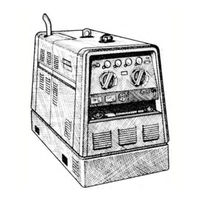
Lincoln Electric COMMANDER 400 SVM133-B Service Manual (197 pages)
Lincoln Electric Welder User Manual
Brand:
Lincoln Electric
| Category:
Welding System
| Size: 4 MB
Table of Contents
Master for All Sections
6
Service Manual
1
Safety
2
California Proposition 65 Warnings
2
Electric and Magnetic Fields
2
Electric Shock Can Kill
3
Fumes and Gases
3
Table of Contents
6
Installation
8
Technical Specifications
8
Angle of Operation
9
Location and Ventilation
9
Safety Precautions
9
Stacking
9
Storing
9
High Altitude Operation
10
Lifting
10
Oil
10
Pre-Operation Engine Service
10
Towing
10
Battery Connections
11
Cooling System
11
Fuel
11
Muffler Outlet Pipe
11
Spark Arrester
11
Cable Installation and Cable Sizes
12
Electrical Output Connections
12
Welding Cable Connections
12
Auxiliary Power Receptacles
13
Machine Grounding
13
Standby Power Connections
13
Commander
14
Connection of the Commander 400 to Premises Wiring
14
Operation Section B Safety Instructions
15
Design Features
15
Operation...............................................................................................................................section B Safety Instructions
15
Recommended Applications
15
Welding Capability
15
Operation
16
General Description
16
Operating Instructions
16
Safety Instructions
16
Design Features
17
Recommended Applications
17
Additional Design Features
18
Welding Capability
18
Controls and Settings
19
Engine Controls
19
Start Pushbutton
19
Welder Controls
21
Auxiliary Power Controls
22
Engine Operation
22
Starting the Engine
22
Wire Feeder Mode Controls
22
Break-In Period
23
Stopping the Engine
23
Typical Fuel Consumption
23
Stick Welding
24
TIG Welding
24
Welder Operation
24
Commander 400 Settings with K799 Hi-Freq./K930-1 Tig Module
25
Tig Torch
25
Auxiliary Power
26
Wire Feed (Constant Voltage) Welding
26
Simultaneous Welding and Auxiliary Power Loads
26
Accessories
27
Accessories
28
Options/Accessories
28
Stick Welding
28
TIG Welding
28
Semiautomatic Welding Accessories
28
Connection of Lincoln Electric Wire Feeders
29
Cable Plug
30
Connection of the K488 SG Control Module and K487 Magnum Spool Gun
35
Table of Contents
37
Maintenance
38
Routine and Periodic Maintenance
38
Change the Oil
38
Engine Maintenance
38
Accessories
39
Maintenance
39
Safety Precautions
38
Change the Oil Filter
39
Fuel
39
Fuel Filters
40
Air Filter
42
Bleeding the Fuel System
42
Cooling System
43
Maintenance Required
44
Cooling Blower Belt
45
Engine Maintenance Parts
45
Battery Maintenance
46
Charging the Battery
46
Checking Electrolyte Level
46
Checking Specific Gravity
46
Cleaning the Battery
46
Welder/Generator Maintenance
47
Cable Connections
47
Name Plates
47
Major Component Locations
48
Theory of Operation Section
49
Theory of Operation
50
Scr Operation
53
Troubleshooting & Repair Section
55
How to Use Troubleshooting Guide
56
Troubleshooting & Repair Section
56
PC Board Troubleshooting Procedures
57
Troubleshooting Guide
58
Troubleshooting and Repair
68
Case Cover Removal and Replacement Procedure
81
Materials Needed
81
Troubleshooting and Repair
82
Left Side Panel
83
Case Front Knobs - Removal and Replacement Procedure
86
Idler Solenoid Test
87
Test Description
87
Test Procedure
88
Shutdown Solenoid Test
89
Engine Throttle Adjustment Test
91
Static Scr/Diode Rectifier Bridge Test
95
Active SCR Test
99
Charging Circuit Test
103
Stator Voltage Test
105
Fine Control Potentiometer Test
109
Troubleshooting and Repair
110
Range Switch Test
111
Shunt Calibration Test
115
Exciter Voltage Feedback Test
117
Exciter Capacitor Bank Test
119
Control Board Power Supply Test
121
Stator Resistance Test
123
Normal Open Circuit Voltage Waveform (115 VAC Supply
126
Scope Settings
126
Normal Open Circuit Voltage Waveform (Stick) Max Tap
127
Normal Weld Voltage Waveform (Stick CC) Machine Loaded to 400 Amps at 40 Volts
128
Normal Weld Voltage Waveform (Wire CV) Machine Loaded to 400 Amps at 40 Volts
129
Normal Open Circuit Voltage Waveform (Wire CV Tap
130
Normal Solenoid Pull & Hold Coil Waveforms
131
Abnormal Solenoid Pull & Hold Coil Waveforms
132
Typical Exciter Voltage Feedback Waveforms
133
Abnormal Exciter Voltage Feedback Waveforms
134
Calibration Procedure
138
Shutdown Solenoid Removal and Replacement
139
Scr/Diode Rectifier Bridge Removal and Replacement
143
SCR Removal and Replacement
149
Special Instructions
150
Mounting Stud Type Diodes to Aluminum Heat Sinks
157
Engine, Stator/Rotor Removal and Replacement
159
Fuel Level Sensor
160
Reassembly Notes
169
Retest after Repair
171
Auxiliary Power Output
171
Electrical Diagrams
174
Advertisement
Advertisement
Related Products
Lincoln Electric SPEEDTEC 400S
Lincoln Electric Invertec 400SX
Lincoln Electric MAGNUM 400FM
Lincoln Electric VANTAGE 400
Lincoln Electric Mobiflex 400-MS
Lincoln Electric STATIFLEX 400-M
Lincoln Electric VANTAGE 400 CE
Lincoln Electric MAGNUM 400 K575
Lincoln Electric MAGNUM 400 K1723
Lincoln Electric SHIELD-ARC 400AS-50
Lincoln Electric Categories
Welding System
Welding Accessories
Flashlight
Wire Feeders
Portable Generator
More Lincoln Electric Manuals
Login
Sign In
OR
Sign in with Facebook
Sign in with Google
Upload manual
Upload from disk
Upload from URL