Sign In
Upload
Manuals
Brands
L3 Communications Manuals
Marine Radio
ProTec AISA1000-10
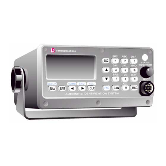
L3 Communications ProTec AISA1000-10 Manuals
Manuals and User Guides for L3 Communications ProTec AISA1000-10. We have
1
L3 Communications ProTec AISA1000-10 manual available for free PDF download: Installation And Operation Manual
L3 Communications ProTec AISA1000-10 Installation And Operation Manual (102 pages)
AUTOMATIC IDENTIFICATION SYSTEM HARDWARE
Brand:
L3 Communications
| Category:
Marine Radio
| Size: 1.21 MB
Table of Contents
Table of Contents
7
Subject/Description
15
SECTION 1 - Protec AIS Introduction
15
General
15
System Overview
15
References
16
Acronyms
17
Figure 1-1. AIS Transponder
18
Figure Title
18
Technical Specifications
18
AIS Description
20
Compact Design
20
Data Interface
20
Integral GPS
20
Integral Minimum Keyboard Display (MKD)
20
Table Title
21
Equipment List
21
Table 1-1. AIS Parts List
21
Operational Modes
22
Autonomous and Continuous
22
Assigned
22
Polled
22
Initialization
22
DSC Functionality
23
AIS Broadcast Parameters
23
AIS Frequencies
24
AIS Input Sentences
24
Interface Description
25
Pilot Systems Input Data and Formats
25
Table 1-2. Pilot System High-Speed Input Data Formats
25
Pilot Systems Output Data and Formats
26
Pilot Input / Output Port
26
Table 1-3. Pilot System High-Speed Output Data Formats
26
Long Range Equipment Interface
27
Table 1-4. Pilot Port Pinout
27
Long Range Input Data and Formats
28
Table 1-5. Long Range Input Data and Formats
28
Long Range Output Data and Formats
29
Table 1-6. Long Range Output Data and Formats
30
Subject/Description
31
Sensor Input Data and Formats
31
Data Field Assignments
31
GPS and Sensor Input Sentences
31
DTM - Datum Reference
31
Table 1-7. Sensor Input Data and Formats
31
GBS - GNSS Satellite Fault Detection
32
GGA - Global Positioning System Fix Data
32
GLL - Geographic Position - Latitude / Longitude
32
GNS - GNSS Fix Data
33
HDT - Heading True
33
RMC - Recommended Minimum Specific GNSS Data
33
ROT - Rate of Turn
34
VBW - Dual Ground / Water Speed
34
1.5.1.10 VTG - Course over Ground and Ground Speed
34
1.5.1.11 ZDA - Time and Date
35
AIS Specific Input Sentences
35
ABM - Addressed Binary and Safety-Related Message
35
ACA - AIS Regional Channel Assignment Message
36
ACK - Acknowledge Alarm
36
AIQ - Query Sentence
36
AIR - AIS Interrogation Request
37
BBM - Broadcast Binary Message
37
SSD - Ship Static Data
37
VSD - Voyage Static Data
38
SECTION 2 - Protec AIS Operation
39
Operation
39
Minimum Keyboard Display
41
Figure 2-1. AIS Transponder
41
Subject/Description
42
Power/DIM Control
42
Liquid Crystal Display
42
Key Pad
42
Pilot Port
42
Keypad Description
42
Data Display Screens
44
NAV Display Screen (Default Screen)
44
Own Ship Information
45
Figure 2-3. Own Ship Data Display
45
Data Entry Screens
46
AIS Main System Menu
46
Logon / Logoff Screen
47
Figure 2-4. AIS Main System Menu
47
Table 2-1. Protec AIS Default Passwords
48
Table 2-2. Password Type Menu Screen Access
48
System Information and Configuration
49
Figure 2-5. Password Entry Screen
49
Figure 2-6. System Information and Configuration Screen
50
Vessel/Voyage Setup
51
Figure 2-7. Vessel Data Setup
52
Table 2-3. Vessel Type Codes
53
Channel Management
54
Antenna Position
55
Figure 2-8. Channel Management Settings Screen
55
Figure 2-9. Antenna Position Screen
55
Figure 2-10. Antenna Position Measurements
56
Text Messaging
57
View Safety Text Log
58
Figure 2-11. Safety Text Message
58
Change Password
59
Figure 2-12. Safety Text Review Screen
59
2.1.4.10 System Alert Screen
60
2.1.4.11 Alarm Status
60
Figure 2-13. Password Change Screen
60
Figure 2-14. System Alert Screen
60
Figure 2-15. Alarm Status Screen
61
Table 2-4. Integrity Alarm Conditions Signalled Using ALR Sentence Formatter
62
2.1.4.12 General Status Screen
63
Figure 2-16. General Status Screen
63
Table 2-5. Sensor Status Indications Signalled Using TXT Sentence Formatter
64
2.1.4.13 Down-Time Log
65
2.1.4.14 LCD Viewing Angle Adjustment
65
Figure 2-17. Down-Time Log Screen
65
2.1.4.15 Baud Rate Setup
66
Figure 2-18. LCD Viewing Angle Adjust Screen
66
Figure 2-19. Baud Rate Setup Screen
66
2.1.4.16 Set AIS Channels
67
Figure 2-20. AIS Channel Setup Screen
67
SECTION 3 - Protec AIS Installation
71
Figure 3-1. AIS Transponder Interconnection Diagram
71
Installation
71
Transponder
72
Connecting the IEC Data Interface Cable
74
Data Channels
74
Table 3-1. Data Channels
74
Data Cable
75
Figure 3-2. AIS Transponder IEC Data Cable
76
Figure 3-3. IEC Data Cable External Wiring Diagram
77
Table 3-2. IEC Cable Pinouts
78
Figure 3-4. AIS Transponder Power Cable
79
Figure 3-5. Pilot Port Cable
80
Table 3-3. Pilot Port Pinout
80
Figure 3-6. AIS Transponder Antenna Diagram
83
Figure 3-7. AIS Transponder Rear View
84
Terminal Block
84
Figure 3-8. AIS Transponder MKD
85
Powerup and Configuration
85
Powerup the Transponder
85
Table 3-4. Protec AIS Default Passwords
86
Vessel / Voyage Setup
86
Figure 3-9. UAIS Main System Menu
87
Figure 3-10. Vessel/Voyage Setup
88
Table 3-5. Vessel Type Codes
89
Antenna Position Configuration
90
Figure 3-11. Antenna Position
90
Figure 3-12. Calculating Antenna Position
90
Figure Title
90
Verify Transponder Linkup to Ship's Dgps & GYRO
91
Figure 4-1. AIS Transponder O&D Drawing with Trunion Bracket
95
Figure 4-2. AIS Transponder O&D Drawing
96
Figure 4-3. IEC Data Cable Interconnect Diagram
97
Advertisement
Advertisement
Related Products
L3 Communications ProTec AISD1000-00
L3 Communications Categories
Marine Radio
Recording Equipment
Security System
Voice Recorder
Security Sensors
More L3 Communications Manuals
Login
Sign In
OR
Sign in with Facebook
Sign in with Google
Upload manual
Upload from disk
Upload from URL