Sign In
Upload
Manuals
Brands
Keysight Technologies Manuals
Recording Equipment
N5511A
Keysight Technologies N5511A Test System Manuals
Manuals and User Guides for Keysight Technologies N5511A Test System. We have
2
Keysight Technologies N5511A Test System manuals available for free PDF download: User Manual, Getting Started Manual
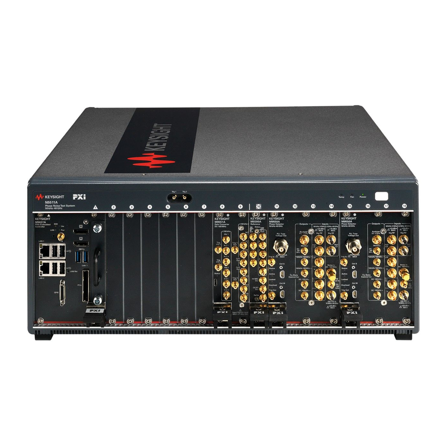
Keysight Technologies N5511A User Manual (369 pages)
Phase Noise Test System
Brand:
Keysight Technologies
| Category:
Test Equipment
| Size: 14 MB
Table of Contents
Table of Contents
5
1 Getting Started
13
Introduction
14
Documentation Map
15
Additional Documentation
16
System Overview
17
2 Introduction
21
Introducing the GUI
22
Designing to Meet Your Needs
24
Beginning
24
N5511A Operation: a Guided Tour
25
Required Equipment
25
How to Begin
25
Powering the System on
26
To Power on a Racked System
26
Starting the Measurement Software
27
Verify License Key Is Installed
29
Powering the System off
30
3 Phase Noise Basics
31
What Is Phase Noise
32
Ideal Vs Real Word Signals
33
Phase Terms
34
4 Expanding Your Measurement Experience
40
GUI Features
40
Viewing Markers
40
Display Preferences
41
Omitting Spurs
43
Displaying the Parameter Summary
45
Exporting Measurement Results
47
Saving Measurement State
51
Recall Measurement State
51
Measurement Preferences
52
Toolbar
53
5 Absolute Measurement Fundamentals
55
The Phase-Lock-Loop Technique
56
Single Channel
56
Dual Channel
58
The Phase-Lock Loop Circuit
60
The Capture and Drift Tracking Ranges
60
Peak Tune Range (PTR)
60
Selecting the VCO Source
62
What Sets the Measurement Noise Floor
63
The System Noise Floor
63
The Noise Level of the Reference Source
64
Selecting a Reference (Single Channel)
65
Using a Similar Device
65
Using a Signal Generator
65
Selecting a Reference (Dual Channel)
66
Tuning Requirements
69
Estimating the Tuning Constant
71
Tracking Frequency Drift
72
Evaluating Beat Note Drift
73
Changing the PTR
74
The Tuning Qualifications
75
Minimizing Injection Locking
76
Adding Isolation
76
Increasing the PLL Bandwidth
77
Inserting a Device
79
An Attenuator
79
An Amplifier
80
Evaluating Noise above the Small Angle Line
82
Determining the Phase-Lock-Loop Bandwidth
82
Calibration
86
Overview
86
Measured Beat Note
87
Single-Sided Spur
91
Double-Sided Spur
95
6 Absolute Measurement Examples
97
Example Overviews
98
Input Ports
99
Single Channel Measurement
100
Required Equipment
100
Test Setup
101
Configuring Equipment
102
Measurement Procedure
103
Dual Channel (EFC)
117
Required Equipment
117
Test Setup
118
Configuring Equipment
120
Measurement Procedure
121
Dual Channel (DCFM)
134
Required Equipment
134
Test Setup
134
Configuring Equipment
136
Measurement Procedure
137
OCXO Dual Channel Measurement
150
Required Equipment
150
Test Setup
151
Configuring Equipment
153
Measurement Procedure
154
7 Residual and Additive Noise Measurement Fundamentals
168
What Is Residual Noise
168
The Noise Mechanisms
168
Fundamental Measurement Technique
170
Assumptions
172
Frequency Translation Devices
173
Calibrating the Measurement
175
User Entry of Phase Detector Constant
177
Measured Beat Note
178
Measured ± DC Peak Voltage
180
Double-Sided Spur
182
Single-Sided Spur
184
Measurement Difficulties
186
System Connections
186
8 Residual Measurement Examples
187
Amplifier Measurement Example - Single Channel
188
Required Equipment
188
Connections
188
Configuring Equipment
189
Measurement Procedure
190
Amplifier Measurement Example - Dual Channel
202
Required Equipment
202
Connections
202
Configuring Equipment
203
Measurement Procedure
204
9 FM Discriminator Fundamentals
217
The Frequency Discriminator Method
218
Basic Theory
218
The Discriminator Transfer Response
219
10 FM Discriminator Measurement Examples
223
Introduction
224
FM Discriminator Single Channel Measurement Using Double-Sided Spur Calibration
225
Required Equipment
225
Determining the Discriminator (Delay Line) Length
226
Define the Measurement
227
Setup Considerations
232
Making the Measurement
236
When the Measurement Is Complete
237
FM Discriminator Single Channel Measurement Using FM Rate and Deviation Calibration
240
Required Equipment
240
Determining the Discriminator (Delay Line) Length
240
Define the Measurement
242
Setup Considerations
247
Making the Measurement
251
When the Measurement Is Complete
252
11 AM Noise Measurement Fundamentals
255
AM-Noise Measurement Theory of Operation
256
Basic Noise Measurement
256
Phase Noise Measurement
256
Amplitude Noise Measurement
257
AM Noise Measurement Block Diagrams
257
Using an External am Detector
258
Calibration and Measurement General Guidelines
260
User Entry of Phase Detector Constant
261
Double-Sided Spur
263
Single-Sided Spur
267
12 AM Noise Measurement Examples
271
AM Noise Measurement Examples
272
Required Equipment
272
Test Setup
272
Configuring Equipment
273
Measurement Procedure
274
13 Baseband Noise Measurement Example
283
Baseband Noise Measurements
284
Baseband Noise with Test Set Measurement Example
285
Define Measurement
285
New Measurement
285
14 Evaluating Your Measurement Results
289
Evaluating the Results
290
Looking for Obvious Problems
290
Comparing against Expected Data
291
Gathering more Data
293
Repeating the Measurement
293
Doing more Research
293
Outputting the Results
294
Using a Printer
294
Graph of Results
295
Marker
295
Omit Spurs
297
Parameter Summary
300
Problem Solving
302
Discontinuity in the Graph
302
Higher Noise Level
303
Spurs on the Graph
304
15 Advanced Software Features
307
Introduction
308
Phase-Lock-Loop Suppression
309
PLL Suppression Parameters
310
Ignore-Out-Of-Lock Mode
312
PLL Suppression Verification Process
313
Accuracy Degradation
321
Blanking Frequency and Amplitude Information on the Phase Noise Graph
322
Security Level Procedure
322
16 Reference Graphs and Tables
327
Approximate System Noise Floor Vs. R Port Signal Level
328
Phase Noise Floor and Region of Validity
329
Phase Noise Level of Various Keysight Sources
330
Increase in Measured Noise as Ref Source Approaches DUT Noise
331
Approximate Sensitivity of Delay Line Discriminator
332
AM Calibration
333
Voltage Controlled Source Tuning Requirements
334
Tune Range of VCO for Center Voltage
335
Peak Tuning Range Required by Noise Level
336
Phase Lock Loop Bandwidth Vs. Peak Tuning Range
337
Noise Floor Limits Due to Peak Tuning Range
338
Tuning Characteristics of Various VCO Source Options
339
17 System Specifications
341
System Specifications
342
Power Requirements
344
18 System Interconnections
345
N5511A System Modules
346
Making Connections
347
Before Connecting the Cables to any Device
347
Proper Connector Torque
347
Connecting a Display to Your System
348
N5511A Two Channel Cable Connections
349
System Connectors
354
19 Preventive Maintenance
357
Using, Inspecting, and Cleaning RF Connectors
358
Repeatability
358
RF Cable and Connector Care
358
Before Connecting the Cables to any Device
359
Proper Connector Torque
359
Connector Wear and Damage
359
2.92 Connector Precautions
359
Cleaning Procedure
360
General Procedures and Techniques
361
Connector Removal
362
Instrument Removal
364
Standard Instrument
364
Half-Rack-Width Instrument
365
Benchtop Instrument
366
Instrument Installation
367
Standard Rack Instrument
367
Half-Rack-Width Instrument
368
Benchtop Instrument
368
Advertisement
Keysight Technologies N5511A Getting Started Manual (94 pages)
Phase Noise Test System
Brand:
Keysight Technologies
| Category:
Recording Equipment
| Size: 5 MB
Table of Contents
Table of Contents
5
1 Initial Setup
7
Introduction
8
Unpacking and Inspecting the System
9
To Unpack a Benchtop System
9
Verify Shipping Contents
10
Remove Shipping Cover
11
System Components
12
Making Connections
13
Before Connecting the Cables to any Device
13
Proper Connector Torque
13
Connecting a Display to Your System
14
Powering the System on
15
To Power on a Racked System
15
Starting the Measurement Software
16
Verify License Key Is Installed
18
Asset Manager
19
Configuring an Asset
19
Powering the System off
25
2 General Information
27
System Overview
28
System Specifications
32
Power Requirements
34
Equipment Installation
35
Test Set Location and Mounting Requirements
36
N5511A Rack Mount Instructions (Optional)
37
Keysight Y1215C Flush Mount Rack Kit
37
General Rack Mounting Guidelines
37
Assembly and Installation
39
Documentation
47
Contacting Keysight Technologies
48
3 System Interconnections
49
N5511A System Modules
50
N5511A Two Channel Cable Connections
51
4 Making a Measurement
57
Making a Single Channel Absolute Phase Noise Measurement
58
Equipment Needed
58
Connections
58
Configuring Equipment
59
Measurement Procedure
60
New Measurement
71
5 Recovery
77
Hard Drive Recovery Process
78
Configuring Recovery Prompt Timing
80
SSD Replacement Procedure
81
Removing the SSD
81
6 Service, Support, and Safety Information
83
Safety and Regulatory Information
84
General
84
Before Applying Power
84
Ground the Instrument
84
Do Not Operate in an Explosive Atmosphere
85
Do Not Operate Near Flammable Liquids
85
Cleaning
85
Do Not Remove Instrument Cover
85
Keep Away from Live Circuits
85
Do Not Operate Damaged Equipment
85
Do Not Block the Primary Disconnect
86
Do Not Modify the Instrument
86
In Case of Damage
86
Safety Symbols and Instrument Markings
87
Regulatory Compliance
89
Service and Support
90
Service and Support Options
90
Contacting Keysight Technologies
91
Return Procedure
92
Determining Your Instrument's Serial Number
92
Shipping Your Analyzer to Keysight for Service or Repair
92
Advertisement
Related Products
Keysight Technologies N4000A
Keysight Technologies N4001A
Keysight Technologies N5102A
Keysight Technologies N5531X
Keysight Technologies N5511A-K26
Keysight Technologies Agilent N5500A
Keysight Technologies PNA-X N5242A
Keysight Technologies N5264A
Keysight Technologies N5172B
Keysight Technologies N5227B
Keysight Technologies Categories
Measuring Instruments
Test Equipment
Control Unit
Portable Generator
Power Supply
More Keysight Technologies Manuals
Login
Sign In
OR
Sign in with Facebook
Sign in with Google
Upload manual
Upload from disk
Upload from URL