Table of Contents
Advertisement
Quick Links
Download this manual
See also:
User Manual
Advertisement
Table of Contents

Related Manuals for Keysight Technologies N5511A


Summary of Contents for Keysight Technologies N5511A
- Page 1 Keysight N5511A Phase Noise Test System Getting Started Guide...
- Page 2 THESE TERMS, THE WARRANTY beyond those set forth in the TERMS IN THE SEPARATE EULA shall apply, except to the © Keysight Technologies, Inc. 2019 AGREEMENT WILL CONTROL. extent that those terms, rights, or No part of this manual may be...
- Page 3 Documentation is updated periodically. For the latest information about these products, including instrument software upgrades, application information, and product information, browse to the following URL: http://www.keysight.com/find/n5511a To receive the latest updates by email, subscribe to Keysight Email Updates at the following URL: http://www.keysight.com/find/MyKeysight...
-
Page 5: Table Of Contents
N5511A Rack Mount Instructions (Optional) ........ - Page 6 Contacting Keysight Technologies ........
-
Page 7: Initial Setup
Keysight N5511A Phase Noise Test System Getting Started Guide Initial Setup “Introduction” on page 8 “Unpacking and Inspecting the System” on page 9 “Making Connections” on page 13 “Powering the System On” on page 15 “Starting the Measurement Software” on page 16 “Asset Manager”... -
Page 8: Introduction
Absolute Phase Noise Measurement as your first measurement. If you need to upgrade the phase noise software in the N5511A system controller for any reason, refer to the N5511A Phase Noise Test System User’s Guide for information and procedures. -
Page 9: Unpacking And Inspecting The System
This section presents procedures for unpacking a benchtop model. Do not attempt to unpack your system without reviewing them. To unpack a benchtop system To unpack an N5511A benchtop system, you need the following tools: — Safety glasses — Utility knife Retain all packing material—front panel instrument cover, boxes, and foam—for future use should... -
Page 10: Verify Shipping Contents
— N5511A Phase Noise Test System - Getting Started Guide — Certificate of Calibration — Power cord The N5511A system is shipped with an AC power cord appropriate for your location. — Instrument connectors and adapters specific to your system —... -
Page 11: Remove Shipping Cover
Unpacking and Inspecting the System Remove Shipping Cover The N5511A system is shipped with a protective cover over the front panel. Remove the cover using a T-20 driver (not included) to remove the 8 screws attaching the cover to the chassis. -
Page 12: System Components
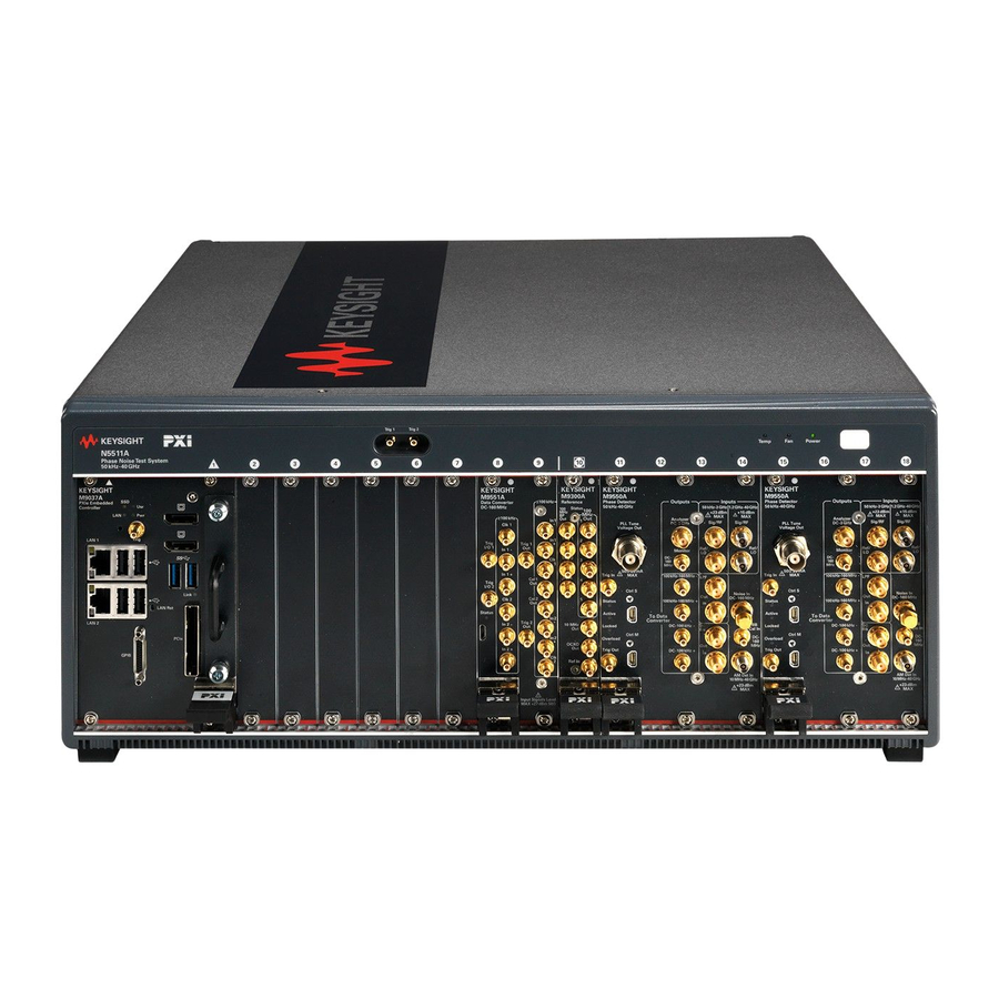
Figure 1-1 Keysight N5511A Phase Noise Test System The N5511A system is available as a benchtop model. Due to the system’s flexibility, the hardware in the system varies with the options selected. You may be installing instruments you already own in the system as well. A typical N5511A system includes these components: —... -
Page 13: Making Connections
3. Lastly, connect the power cord(s) to the AC power supply. Before connecting the cables to any device: Keysight Technologies recommends the use of adaptors as connector savers to extend the lifespan of the test ports on the N5511A Phase Noise Test System. -
Page 14: Connecting A Display To Your System
Making Connections Connecting a Display to your System The N5511A Phase noise test system does not have a display. You will have to provide a monitor to view the user interface. Connect a display port cable to the M9037A controller display port connection and your monitor. -
Page 15: Powering The System On
Connect your system to an appropriate AC power source using the power cord provided. The N5511A system is shipped with an AC power cord appropriate for your location. Before applying power, make sure the AC power input and the location of the system meet the... -
Page 16: Starting The Measurement Software
Phase Noise Test System. Connecting the PC to a Local Area Network (LAN), without first installing internet security software (firewall, virus protection, etc) puts both your PC and data at risk. If you decide to connect the N5511A to a LAN, without first installing internet security software, you do so at your own risk. - Page 17 Windows start menu. Click Start > All Programs > Keysight N5510 > N5510 User Interface. 2. When the program starts, the main N5510 measurement window appears (see Figure 1-5). It shows the phase noise graph. Figure 1-5 Main N5510 user interface window N5511A Phase Noise Test System Getting Started Guide...
-
Page 18: Verify License Key Is Installed
Starting the Measurement Software Verify License Key is Installed The N5511A will have the license key already installed, but if you ever need to install the license key, use the following procedure. 3. Use the Keysight License Manager to see the license keys installed. Start >... -
Page 19: Asset Manager
Asset Manager Asset Manager The Asset Manager adds assets to the N5511A system. All the test sets and digitizers should be installed at the factory. The procedure is essentially the same for any asset. We use a source as an example. Adding an asset involves two steps, once the hardware connections have been made: —... - Page 20 Navigate to Add in Asset Manager 3. Refer to Figure 1-9. From the Asset Type pull-down list in Choose Asset Role dialog box, select Source, then click Next. Figure 1-9 Select source as asset type N5511A Phase Noise Test System Getting Started Guide...
- Page 21 5. Refer to Figure 1-11. From the Interface pull-down list, select TCPIP0. 6. In the Address box, type the IP address of the source. Figure 1-11 Select Interface, Address, and I/O Library N5511A Phase Noise Test System Getting Started Guide...
- Page 22 Keysight E1430 VXI digitizer Keysight E1437 VXI digitizer Keysight E1420B VXI counter Keysight E1441 VXI ARB Keysight GPIB slave port 7. In the Library pull-down list, select the Keysight Technologies VISA. Click the Next button. N5511A Phase Noise Test System Getting Started Guide...
- Page 23 Click Finish. Figure 1-13 Enter comment 10.Refer to Figure 1-14. In the Asset Manager window, select the source in the left window pane. Click the check-mark button on the toolbar to verify connectivity. N5511A Phase Noise Test System Getting Started Guide...
- Page 24 The Asset Manager displays a message verifying the connection to your asset. This indicates that you have successfully used the Asset Manager to configure a source. 11.To exit the Asset Manager, on the menu select Server/Exit. N5511A Phase Noise Test System Getting Started Guide...
-
Page 25: Powering The System Off
Powering the System Off 1. On the N5510 software menu, select File\Exit, Start icon, then shut down. Always shut down the N5510 software before powering off the N5511A system. 2. Use the Start menu to shut down the PC. Press the power switch on each instrument to the off position. - Page 26 Initial Setup Powering the System Off N5511A Phase Noise Test System Getting Started Guide...
-
Page 27: General Information
“N5511A Rack Mount Instructions (Optional)” on page 37 “Documentation” on page 47 “Contacting Keysight Technologies” on page 48 This chapter introduces you to the Keysight N5511A Phase Noise Test System. It contains an overview of the system, system specifications, and cable connections. -
Page 28: System Overview
PLL/reference-source technique, and delay-line and FM-discriminator methods. The N5511A system is available as a benchtop model. Due to the system’s flexibility, the hardware in the system varies greatly with the options selected. You may be installing instruments you already own in the system as well. A typical N5511A system includes these components: —... - Page 29 N5511A Phase Noise Test System. The N5511A can replace earlier Keysight E5505A phase noise systems. The N5511A system uses a LAN or USB/GPIB port to communicate with the assets in the system. However, the N5511A system and N5510 software are backwards compatible with earlier E5505A systems and instruments.
- Page 30 General Information System Overview Figure 2-2 Keysight E5505A system comparison to N5511A system, typical configuration N5511A Phase Noise Test System Getting Started Guide...
- Page 31 50 kHz - 40 GHz phase detector M9550A N5500A-201 50kHz - 26.5 GHz Baseband Test Set FFT/ Data Converter DC - 160 MHz M9551A E5505A-RHK PC with data converter card and swept analyzer N5511A Phase Noise Test System Getting Started Guide...
-
Page 32: System Specifications
Table 2-3 shows the system’s operating characteristics. The N5511A Phase Noise Test System is designed for indoor use only. This product is designed for use in Installation Category II and Pollution Degree 2. Table 2-2 Mechanical and environmental specifications... - Page 33 500 kHz to 5.0 MHz 0.01 Hz to 2.0 MHz 5.0 MHz to 50 MHz 0.01 Hz to 20 MHz 50 MHz to 400 MHz 0.01 Hz to 160 MHz 400 MHz to 40 GHz N5511A Phase Noise Test System Getting Started Guide...
-
Page 34: Power Requirements
General Information System Specifications Power requirements The flexibility of the N5511A system configuration results in a significant range of power requirements, depending on the type and number of instruments in a system. Table 2-6 shows the power requirements of the N5511A chassis/test set. -
Page 35: Equipment Installation
Instruments that appear damaged or defective should be made inoperative and secured against unintended operation until they can be repaired by qualified service personnel. N5511A Phase Noise Test System Getting Started Guide... -
Page 36: Test Set Location And Mounting Requirements
Refer to the section “N5511A Rack Mount Instructions (Optional)” information on installing the system in a rack mount. Figure 2-3 Keysight N5511A Phase Noise Test System Front View N5511A Phase Noise Test System Getting Started Guide... -
Page 37: N5511A Rack Mount Instructions (Optional)
If instruments or modules in the chassis are consuming maximum power, 1U of rack space is required for ventilation below the chassis. If there are any concerns or special requirements a Keysight Field Engineer should be consulted to assure instrument(s) temperature compliance and performance. N5511A Phase Noise Test System Getting Started Guide... - Page 38 M4 x 0.7 x 10 mm Phillips Flat Head Screws w Patch Lock (8 on brackets, 4 on handle) 0515-5827 M5 x 0.8 x 8 mm Phillips Flat Head Screws w/Patch Lock 8710-2727 Offset Screwdriver. Used to tighten the dress screws. N5511A Phase Noise Test System Getting Started Guide...
-
Page 39: Assembly And Installation
Y1215C Flush Mount Rail Kit Installed on a Rack - Note: For clarity, the rack sides and PXIe chassis are not shown If you are installing on a N5511A PNTS chassis, the Rear Bracket assemblies are not required. N5511A Phase Noise Test System Getting Started Guide... - Page 40 General Information N5511A Rack Mount Instructions (Optional) Figure 2-5 Center Holes of Rack, Attaching Channel Nuts - Note: Right side of rack is shown N5511A Phase Noise Test System Getting Started Guide...
- Page 41 1. Optional step. If you are using handles, attach the front handles to the Front Mounting Brackets. See Figure 2-6. Figure 2-6 Y1215C Flush Mount Rack Kit Handle to Front Bracket Assembly N5511A Phase Noise Test System Getting Started Guide...
- Page 42 2680-0278 10-32 screws (supplied with the Y1217A Rail Kit). Slide channel nuts over the rack holes to be used by the support rails. Figure 2-7 Attaching the Support Rails to the Rack N5511A Phase Noise Test System Getting Started Guide...
- Page 43 General Information N5511A Rack Mount Instructions (Optional) 4. See Figure 2-8. Install the two M9018-00208 Nut Brackets in the channel of the rack. Figure 2-8 Nut Bracket Installation N5511A Phase Noise Test System Getting Started Guide...
- Page 44 6. Remove the four chassis feet by pulling out the small rubber insert on each foot and then removing the Phillips screw that attaches the foot to the chassis. Figure 2-9 Removing the chassis feet, side handles, and shipping screws N5511A Phase Noise Test System Getting Started Guide...
- Page 45 When you slide the front bracket up against the rack vertical columns, the 2680-0278 screws (see Figure 2-8) used to secure the M9018-00208 Nut Bracket to the rack will protrude through holes on the front bracket. N5511A Phase Noise Test System Getting Started Guide...
- Page 46 You should always put the feet down on the rack for better phase noise measurements. Figure 2-11 Closeup of left side front Y1215C Front Bracket N5511A Phase Noise Test System Getting Started Guide...
-
Page 47: Documentation
General Information Documentation Documentation Documentation is updated periodically. For the latest information about these products, including instrument software upgrades, application information, and product information, browse to the following URL: http://www.keysight.com/find/n5511a N5511A Phase Noise Test System Getting Started Guide... -
Page 48: Contacting Keysight Technologies
Assistance with test and measurements needs and information or finding a local Keysight office are available on the Web at: http://www.keysight.com/find/assist Contact Keysight for service: http://www.keysight.com/find/support For product specific information and support, software and documentation updates, browse to the following URL: http://www.keysight.com/find/n5511a N5511A Phase Noise Test System Getting Started Guide... -
Page 49: System Interconnections
Phase Noise Test System. Connecting the PC to a Local Area Network (LAN), without first installing internet security software (firewall, virus protection, etc) puts both your PC and data at risk. If you decide to connect the N5511A to a LAN, without first installing internet security software, you do so at your own risk. -
Page 50: N5511A System Modules
System Interconnections N5511A System Modules N5511A System Modules Figure 3-1 N5511A System Modules N5511A Phase Noise Test System Getting Started Guide... -
Page 51: N5511A Two Channel Cable Connections
Cable Group Cable Part Numbers White Clock 8120-5091 (120 mm) Green Phase Detector Test Set 1 8121-2175 (300 mm) Phase Detector Test Set 2 8121-2175 (300 mm) Blue FFT/Data Converter 8121-2175 (300 mm) N5511A Phase Noise Test System Getting Started Guide... - Page 52 ≥ 156 kHz Clk 1 100 MHz Out 1 ≤ 156 kHz Clk 1 100 MHz Out 2 ≥ 156 kHz Clk 2 100 MHz Out 3 ≤ 156 kHz Clk 2 100 MHz Out 4 N5511A Phase Noise Test System Getting Started Guide...
- Page 53 ≥ 156 kHz IN 1 + 156 kHz - 100 MHz + ≤ 156 kHz IN 1 − DC - 156 kHz − ≤ 156 kHz IN 1 + DC - 156 kHz + N5511A Phase Noise Test System Getting Started Guide...
- Page 54 ≥ 156 kHz IN 2 + 156 kHz - 100 MHz + ≤ 156 kHz IN 2 − DC - 156 kHz − ≤ 156 kHz IN 2 + DC - 156 kHz + N5511A Phase Noise Test System Getting Started Guide...
- Page 55 M9551A M955xA ≤ 156 kHz CAL 1 BB Cal In DC - 100 MHz TEST SET 1 ≤ 156 kHz CAL 2 BB Cal In DC - 100 MHz TEST SET 2 N5511A Phase Noise Test System Getting Started Guide...
- Page 56 System Interconnections N5511A Two Channel Cable Connections N5511A Phase Noise Test System Getting Started Guide...
-
Page 57: Making A Measurement
N5511A Phase Noise Test System Getting Started Guide Making a Measurement “Making a Single Channel Absolute Phase Noise Measurement” on page 58 This chapter contains procedures for making a Single Channel Absolute Phase Noise Measurement to verify that all system assets are communicating. -
Page 58: Making A Single Channel Absolute Phase Noise Measurement
Making a Single Channel Absolute Phase Noise Measurement Making a Single Channel Absolute Phase Noise Measurement This measurement example uses Electronic Frequency Control (EFC). Refer to the N5511A Phase Noise Test System User’s Guide for other methods to make an absolute phase noise measurement. -
Page 59: Configuring Equipment
Frequency: 3 GHz Amplitude: 14 dBm RF On/Off: RF ON Mod On/Off: MOD OFF The RF power of the DUT source must be at least 3 dB lower than that of the REF source. N5511A Phase Noise Test System Getting Started Guide... -
Page 60: Measurement Procedure
If the application is not already started, click on the icon OR go to the Windows Start Menu. From the Windows Start Menu, navigate to the N5510 application software: Start, All Programs, Keysight N5510 User Interface Figure 4-2 N5510 Application Software N5511A Phase Noise Test System Getting Started Guide... - Page 61 At the top of the main application window, click Define and then select Measurement from the drop-down menu. Define, Measurement, Type and Range This window will appear: Figure 4-3 Measurement Type and Range N5511A Phase Noise Test System Getting Started Guide...
- Page 62 Single channel can only use flexible. 3) Choose Channel Setup Channel Setup: Single 4) Set Start and Stop Offsets Start Offset: 100 Hz Stop Offset: 160 MHz N5511A Phase Noise Test System Getting Started Guide...
- Page 63 Next, we will configure the settings for the DUT and the reference source (REF). Navigate to the Source tab at the top of the current window and the following will appear: Figure 4-4 Sources Tab N5511A Phase Noise Test System Getting Started Guide...
- Page 64 Power 14 dBm 3) VCO Tuning Parameters Nominal Tune Constant: 210 Hz/V Tune Range: 0.5 V Input Resistance: 1E+6 (1 MOhm)* * VCO tuning is dependent to the source used as the reference N5511A Phase Noise Test System Getting Started Guide...
- Page 65 Navigate to the Cal tab. The following window would appear: Figure 4-5 Cal Tab For this measurement, use the Beat Note Cal. Refer to the Cal Demo Guide for details on using other cal methods. N5511A Phase Noise Test System Getting Started Guide...
- Page 66 Derive detector constant from measured beat note 2) Configure VCO Tune Constant Settings VCO Tune Constant: Measure VCO tune constant 3) Phase Locked Loop Suppression Uncheck "Verify calculated phase locked loop suppression? N5511A Phase Noise Test System Getting Started Guide...
- Page 67 Making a Measurement Making a Single Channel Absolute Phase Noise Measurement Block Diagram Configuration Navigate to the Block Diagram tab. The following window should appear: Figure 4-6 Block Diagram Tab N5511A Phase Noise Test System Getting Started Guide...
- Page 68 Phase Detector: Automatic Detection Selection 2) Carrier Source select manual 3) Reference Source select previously setup reference E8257C (a green check mark should appear) 4) Test Set Tune Voltage select VCO Tune Mode: EFC N5511A Phase Noise Test System Getting Started Guide...
- Page 69 Making a Measurement Making a Single Channel Absolute Phase Noise Measurement Configure Graph Navigate to the Graph tab. The following window should appear: Figure 4-7 Graph Tab N5511A Phase Noise Test System Getting Started Guide...
- Page 70 1) Set Title Absolute Phase Noise Measurement 2) Set X-Scale X-Scale Minimum: 100 Hz X-Scale Maximum: 160 MHz 3) Set Y-Scale Y-Scale Maximum: 0 dBc/Hz Y-Scale Minimum: -170 dBc/Hz 4) Close Measurement Setup Window N5511A Phase Noise Test System Getting Started Guide...
-
Page 71: New Measurement
Making a Measurement Making a Single Channel Absolute Phase Noise Measurement New Measurement "New Measurement" by clicking on the Measurement tab and selecting Select New Measurement. Figure 4-8 Connection Diagram Press Continue N5511A Phase Noise Test System Getting Started Guide... - Page 72 Establish a beat note less than 1.75 Hz. Currently the REF PSG and DUT PSG are offset in frequency from each other (beat note) by 6.47 Hz. Figure 4-10 6.47 Hz Beat Note N5511A Phase Noise Test System Getting Started Guide...
- Page 73 This is "phase noise" and any deviation from 0V DC is captured by the ADC module in the N5511A and using phase detector constant (in V/rad), will be converted to a phase deviation that is Fourier transformed and processed in frequency "segments"...
- Page 74 Making a Measurement Making a Single Channel Absolute Phase Noise Measurement Figure 4-12 Single Channel Flexible Measurement No Averages Figure 4-13 Single Channel Flexible Measurement 10 Averages N5511A Phase Noise Test System Getting Started Guide...
- Page 75 Making a Measurement Making a Single Channel Absolute Phase Noise Measurement Figure 4-14 Single Channel Flexible Measurement 10 Averages with Markers N5511A Phase Noise Test System Getting Started Guide...
- Page 76 Making a Measurement Making a Single Channel Absolute Phase Noise Measurement N5511A Phase Noise Test System Getting Started Guide...
-
Page 77: Recovery
Keysight N5511A Phase Noise Test System Getting Started Guide Recovery “Hard Drive Recovery Process” on page 78 “Configuring recovery prompt timing” on page 80 “SSD Replacement Procedure” on page 81... -
Page 78: Hard Drive Recovery Process
Using the Keysight Recovery System in conjunction with a regular back up strategy should enable you to fully recover the computer software and data. N5511A Phase Noise Test System Getting Started Guide... - Page 79 Additional recovery steps may be required to fully recover the system to a more current working state. This could involve restoring your own backups of the computer configuration, including re-installing applications, data, and performing system customizations. N5511A Phase Noise Test System Getting Started Guide...
-
Page 80: Configuring Recovery Prompt Timing
— select the Time to display recovery option when needed check box and change the seconds to delay for it You must be logged in as an administrator to change these settings. N5511A Phase Noise Test System Getting Started Guide... -
Page 81: Ssd Replacement Procedure
1. Disconnect the instrument from ac power. 2. Refer to Figure 5-1. Use a #1 Phillips screwdriver to loosen the two screws which attach the SSD to the Controller. Figure 5-1 Controller Module and SSD N5511A Phase Noise Test System Getting Started Guide... - Page 82 4. Install the new Replacement Solid State drive into the M9037A controller. 5. Tighten the 2 screws. Torque to 6 inch-pounds. 6. Go to Keysight license manager software and get the HostID "PCSERNO,XXXXXXXXXX", so the licenses can be re-hosted to the new SSD. N5511A Phase Noise Test System Getting Started Guide...
-
Page 83: Service, Support, And Safety Information
Keysight N5511A Phase Noise Test System Getting Started Guide Service, Support, and Safety Information “Safety and Regulatory Information” on page 84 “Service and Support” on page 90 “Contacting Keysight Technologies” on page 91 “Return Procedure” on page 92 This chapter provides safety and regulatory information, which you should review prior to working with your Keysight system. -
Page 84: Safety And Regulatory Information
Failure to comply with these precautions or with specific warnings or operating instructions in the product manuals violates safety standards of design, manufacture, and intended use of the instrument. Keysight Technologies assumes no liability for the customer's failure to comply with these requirements. General This product has been designed and tested in accordance with accepted industry standards, and has been supplied in a safe condition. -
Page 85: Do Not Operate In An Explosive Atmosphere
REMOVE POWER and do not use the product until safe operation can be verified by service trained personnel. If necessary, return the product to a Keysight Technologies Sales and Service Office for service and repair to ensure the safety features are maintained. -
Page 86: Do Not Block The Primary Disconnect
In the event of a module exceeding the full temperature range, always allow the module to cool before touching or removing modules from the chassis. N5511A Phase Noise Test System Getting Started Guide... -
Page 87: Safety Symbols And Instrument Markings
Forty years is the expected useful life of the product. This symbol on all primary and secondary packaging indicates compliance to China standard GB 18455-2001. N5511A Phase Noise Test System Getting Started Guide... - Page 88 Service, Support, and Safety Information Safety and Regulatory Information South Korean Certification (KC) mark; includes the marking’s identifier code which follows this format: MSIP-REM-YYY-ZZZZZZZZZZZZZZ. Keysight email address N5511A Phase Noise Test System Getting Started Guide...
-
Page 89: Regulatory Compliance
Acoustic statement: (European Machinery Directive) Acoustic noise emission LpA <72 dB Operator position Normal operation mode per ISO 7779 To find a current Declaration of Conformity for a specific Keysight product, go http://www.keysight.com/go/conformity N5511A Phase Noise Test System Getting Started Guide... -
Page 90: Service And Support
The standard warranty is a one-year return to Keysight Technologies factory service warranty. There are many other repair and calibration options available from the Keysight Technologies support organization. These options cover a range of service agreements with varying response times. Contact Keysight for additional information on available service agreements for this product. -
Page 91: Contacting Keysight Technologies
In any correspondence or telephone conversation, refer to the Keysight product by its model number and full serial number. With this information, the Keysight representative can determine the warranty status of your unit. N5511A Phase Noise Test System Getting Started Guide... -
Page 92: Return Procedure
Shipping Your Analyzer to Keysight for Service or Repair Keysight Technologies reserves the right to reformat or replace the internal hard disk drive in your analyzer as part of its repair. This will erase all user information stored on the hard disk. It is imperative, therefore, that you make a backup copy of your critical test data located on the analyzer’s hard disk before shipping it to Keysight for repair. - Page 93 ANY SHAPE AS PACKAGING MATERIALS. They do not adequately cushion the instrument or prevent it from moving in the shipping container. Styrene pellets can also cause equipment damage by generating static electricity or by lodging in fan motors. N5511A Phase Noise Test System Getting Started Guide...
- Page 94 This information is subject to change without notice. © Keysight Technologies 2019 Edition 1, September 2019 N5511-90001 www.keysight.com...
Need help?
Do you have a question about the N5511A and is the answer not in the manual?
Questions and answers