Sign In
Upload
Manuals
Brands
KAESER KOMPRESSOREN Manuals
Controller
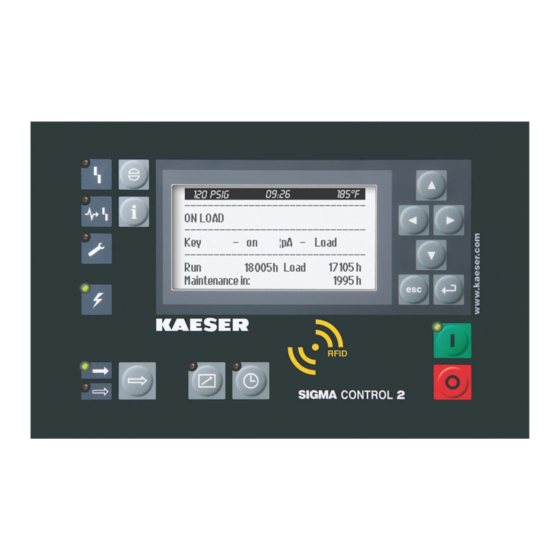
SIGMA CONTROL 2
KAESER KOMPRESSOREN SIGMA CONTROL 2 Manuals
Manuals and User Guides for KAESER KOMPRESSOREN SIGMA CONTROL 2. We have
8
KAESER KOMPRESSOREN SIGMA CONTROL 2 manuals available for free PDF download: User Manual, Service Manual
KAESER KOMPRESSOREN SIGMA CONTROL 2 User Manual (260 pages)
Brand:
KAESER KOMPRESSOREN
| Category:
Controller
| Size: 3 MB
Table of Contents
Table of Contents
3
Quick Reference Guide
10
Operating Elements
10
Fig. 1 Operating Elements
10
Tab. 1 Operating Elements
10
Display Elements
11
Fig. 2 Display Elements
11
Main Menu Overview
12
Functions Overview
12
Tab. 2 Display Elements
12
Tab. 3 Main Menu Overview
12
About this Document
15
Warning Notices
15
Material Damage Warnings
15
Tab. 5 Signal Words and Their Consequences
15
Symbols and Pictograms
16
Copyright
16
Tab. 6 Symbols and Pictograms
16
Software
17
Approvals
17
Updating the Manual
18
Technical Data
19
SIGMA CONTROL 2 Controller
19
Display
19
Tab. 7 Versions and Options
19
Tab. 8 Electrical and Mechanical Specifications
19
Interfaces
20
Fig. 3 MCS Interfaces
20
Tab. 9 Display
20
Fig. 4 MCSIO Interfaces
21
Tab. 10 MCS Interfaces
21
Tab. 11 MCSIO Interfaces
21
MCSIO Inputs and Outputs
22
Input/Output Modules
22
Tab. 12 RFID
22
Tab. 13 Number of Internal Inputs and Outputs
22
Tab. 14 Cable Lengths
22
Electrical Connection Data IOM
23
Tab. 15 IOM
23
Tab. 16 IOM
23
Tab. 17 IOM
23
Maximum Cable Lengths
24
Input/Output Modules - Degree of Protection
24
Input/Output Modules - Dimensions
24
Sensors
24
Pressure Transducer
24
Tab. 18 Electrical Connection Data
24
Tab. 19 Cable Lengths
24
Tab. 20 Degree of Protection, IOM
24
Tab. 21 IOM Dimensions
24
Resistance Thermometer
25
Tab. 22 Pressure Transducer
25
Tab. 23 Resistance Thermometer
25
Safety and Responsibility
26
Intended Use
26
Improper Use
26
Design and Function
27
Controller Overview
27
Components
27
Functions
28
Fig. 5 MCS System Configuration with IOM
28
Fig. 6 MCSIO System Configuration
28
Control Panel
29
Operating Elements
29
Fig. 7 Operating Elements
29
RFID Reader
30
Fig. 8 RFID Reader
30
Tab. 24 Operating Elements
30
Tab. 25 RFID Reader
30
Display Elements
31
Fig. 9 Display Elements
31
Display
32
Operating Display
32
Tab. 26 Display Elements
32
Tab. 27 Machine-Dependent Data in the Header
33
Machine Status
33
Main Menu
33
Parameters
34
Activating Keys
34
Tab. 28 Reset Tick Box Status
34
User Log-In Via RFID Equipment Card
35
Tab. 29 Tick Box Status
35
Kaeser Connect
36
Fig. 10 KAESER CONNECT for SIGMA CONTROL
36
Menu Structure
38
Tab. 31 Main Menu Structure
41
Status Menu
42
Tab. 32 Status Menu
43
Configuration Menu
44
Tab. 33 Configuration Menu
46
Tab. 34 Pressure Control Menu
47
Tab. 35 I/O Peripherals Menu
49
Communication Menu
50
Tab. 36 Communication Menu
50
Connections Menu
51
Components Menu
51
Tab. 37 Connections Menu
51
Tab. 38 Components Menu
51
Power Switching Menu
52
Tab. 39 Power Switching Menu
53
Operating Points and Control Modes
54
Machine Operating Points
54
Control Modes
54
Variable Speed Control with Frequency Converter (SFC)
56
Commissioning
57
Topic Overview
57
Controller Settings
57
Selecting a Menu Item
58
Language
59
Tab. 40 Available Languages
59
User Log-In
60
Fig. 11 RFID Equipment Card Reverse Side
60
Fig. 12 User Log-In Via RFID Equipment Card
61
Fig. 13 Log-In Via RFID Equipment Card
62
Fig. 14 Logging in Manually
63
Date and Time
64
Display Formats
68
Tab. 41 Date Formats
68
Tab. 42 Settings Options for the Time Format
69
Pressure Units
69
Tab. 43 Settings Options for the Pressure Units
70
Tab. 44 Settings Options for the Temperature Units
70
Display
71
Tab. 45 Display Backlight
71
Contrast and Brightness
72
Remote Control" Key
72
IP Configuration
73
Tab. 46 Network Parameters
74
E-Mail
75
Tab. 47 E-Mail Parameters
76
Kaeser Connect
77
Accessing KAESER CONNECT
77
Fig. 15 Log-In Window
77
System Status Menu
78
Advertisement
KAESER KOMPRESSOREN SIGMA CONTROL 2 User Manual (246 pages)
Brand:
KAESER KOMPRESSOREN
| Category:
Controller
| Size: 6 MB
Table of Contents
Table of Contents
3
SIGMA CONTROL 2 Quick Reference Guide
11
Operating Elements
11
Fig. 1 Operating Elements
11
Tab. 1 Operating Elements
11
Indicator Elements
12
Fig. 2 Indicator Elements
12
Tab. 2 Indicator Elements
12
Main Menu Overview
13
Functions Overview
13
Tab. 3 Main Menu Overview
13
Tab. 4 Functions Overview
14
Regarding this Document Using this Document
16
Copyright
16
Software
16
Certification
17
Updating the Operating Manual
17
Symbols and Labels
17
Warnings
17
Potential Damage Warnings
18
Tab. 5 Danger Levels and Their Definition (Personal Injury)
18
Tab. 6 Danger Levels and Their Definition (Damage to Property)
18
Other Alert Notes and Their Symbols
19
Tab. 7 Formatting Options
19
Technical Specifications 3.1 Controller SIGMA CONTROL 2
20
Versions and Options
20
User Interface with Display, CPU and Interfaces
20
Tab. 8 Versions and Options
20
Tab. 9 User Interface
20
Fig. 3 MCS Interfaces
21
Tab. 10 Display Data
21
Tab. 11 MCS Interfaces
21
Fig. 4 MCSIO Interfaces
22
Tab. 12 MCSIO Interfaces
22
In- and Outputs with MCSIO
23
Input/Output Modules
23
Tab. 13 RFID
23
Tab. 14 Number of Internal Inputs and Outputs
23
Tab. 15 Cable Lengths
23
Tab. 16 SC2IOM-1
24
Tab. 17 SC2IOM-2
24
Tab. 18 SC2IOM-3
24
Sensors
25
Tab. 19 Power Supply Specifications
25
Tab. 20 Cable Lengths
25
Tab. 21 Degree of Protection, IOM
25
Tab. 22 IOM Dimensions
25
KAESER I.box
26
Versions and Options
26
Tab. 23 Pressure Transducer
26
Tab. 24 Resistance Thermometer
26
Tab. 25 Modem I.box − Versions and Options
26
Indicator Elements and Interfaces
27
Technical Specifications
27
Fig. 5 KAESER I.box − Indicator Elements and Interfaces
27
Tab. 26 Technical Data KAESER I.box
28
Safety and Responsibility Basic Instructions
29
Specified Use
29
Improper Use
29
Design and Function
30
Controller Overview
30
Fig. 6 MCS System Design with IOM
31
Fig. 7 MCSIO System Design
31
Operating Panel
32
Operating Elements
32
Fig. 8 Operating Elements
32
Display Elements
33
Fig. 9 Display Elements
33
Tab. 27 Operating Elements
33
RFID Reader
34
Display
34
Fig. 10 RFID Reader
34
Tab. 28 Display Elements
34
Tab. 29 RFID Reader
34
Operating Mode
35
Tab. 30 Data in the Header Depending on the Machine Type
35
Main Menu
36
Setting Parameters
36
Activating Keys with Check Boxes
37
Access Control
37
Tab. 31 Reset Check Box Status
37
Tab. 32 Check Box Status
37
Kaeser Connect
38
Fig. 11 KAESER CONNECT for SIGMA CONTROL
38
KAESER I.box
39
Tab. 33 KAESER CONNECT Functions
39
Menu Overview
40
Operating Mode
40
Fig. 12 Overview of KAESER I.box
40
Menu Structure
41
Tab. 34 Menu Structure of Main Menu
44
Tab. 35 Status Menu
46
Tab. 36 Configuration Menu
50
Tab. 37 Pressure Control Menu
51
Tab. 38 I/O Periphery Menu
54
Tab. 39 Communication Menu
56
Tab. 40 Connections Menu
56
Tab. 41 Components Menu
57
Tab. 42 Power Switching Menu
59
Operating Points and Control Modes
60
Machine Operating Points
60
Control Modes
60
Variable Speed Drive with Frequency Converter (SFC)
62
MODULATING Control
63
Installation and Operating Conditions
64
Maintaining Ambient Conditions
64
Installation Conditions
64
Installation
65
Reporting Transport Damage
65
Machine Identification
65
Assembly of the KAESER I.box
65
Tab. 43 Machine Identification
65
Tab. 44 Remote Control Identification
65
Tab. 45 Machine Identification
65
Initial Start-Up Outline
66
Setting the Controller
66
Selecting Menu Options
67
Setting the Language
68
KAESER KOMPRESSOREN SIGMA CONTROL 2 User Manual (232 pages)
Brand:
KAESER KOMPRESSOREN
| Category:
Controller
| Size: 5 MB
Table of Contents
Table of Contents
3
SIGMA CONTROL 2 Quick Installation Guide
11
Operating Elements
11
Fig. 1 Operating Elements
11
Display Elements
12
Main Menu - Overview
12
Fig. 2 Display Elements
12
Tab. 2 Display Elements
12
Functions - Overview
13
Tab. 3 Main Menu - Overview
13
Tab. 4 Functions - Overview
14
Regarding this Document Using this Document
15
Copyright
15
Software
15
Certification
16
Updating the Operating Manual
16
Symbols and Labels
16
Warnings
16
Potential Damage Warnings
17
Tab. 5 Danger Levels and Their Definition (Personal Injury)
17
Tab. 6 Danger Levels and Their Definition (Damage to Property)
17
Other Alerts and Their Symbols
18
Tab. 7 Formatting Options
18
Technical Specifications Controller SIGMA CONTROL
19
Versions and Options
19
User Interface with Display, CPU and Interfaces
19
Tab. 8 Versions and Options
19
Tab. 9 User Interface
19
Fig. 3 MCS Interfaces
20
Tab. 10 Display Data
20
Tab. 11 MCS Interfaces
20
Fig. 4 MCSIO Interfaces
21
Tab. 12 MCSIO Interfaces
21
In- and Outputs with MCSIO
22
Input/Output Modules
22
Tab. 13 RFID
22
Tab. 14 Number of Internal Inputs and Outputs
22
Tab. 15 Cable Lengths
22
Tab. 16 SC2IOM-1
23
Tab. 17 SC2IOM-2
23
Tab. 18 SC2IOM-3
23
Sensors
24
Tab. 19 Power Supply Specifications
24
Tab. 20 Cable Lengths
24
Tab. 21 Degree of Protection, IOM
24
Tab. 22 IOM Dimensions
24
Tab. 23 Pressure Transducer
25
Tab. 24 Resistance Thermometer
25
Safety and Responsibility Basic Instructions
26
Specified Use
26
Improper Use
26
Design and Function
27
Controller Overview
27
Fig. 5 MCS System Design with IOM
28
Fig. 6 MCSIO System Design
28
Operating Panel
29
Operating Elements
29
Fig. 7 Operating Elements
29
Display Elements
30
Fig. 8 Display Elements
30
Tab. 25 Operating Elements
30
RFID Reader
31
Display
31
Fig. 9 RFID Reader
31
Tab. 26 Display Elements
31
Tab. 27 RFID Reader
31
Operating Mode
32
Tab. 28 Data in the Header Depending on the Machine Type
32
Main Menu
33
Setting Parameters
33
Activating Keys with Check Boxes
34
Access Rights
34
Tab. 29 Reset Check Box Status
34
Tab. 30 Check Box Status
34
Kaeser Connect
35
Fig. 10 KAESER CONNECT for SIGMA CONTROL
35
Menus - Overview
36
Operating Mode
36
Tab. 31 KAESER CONNECT Functions
36
Menu Structure
37
Tab. 32 Menu Structure of Main Menu
40
Tab. 33 Status Menu
41
Tab. 34 Configuration Menu
44
Tab. 35 Pressure Control Menu
45
Tab. 36 I/O Periphery Menu
48
Tab. 37 Communication Menu
50
Tab. 38 Connections Menu
50
Tab. 39 Components Menu
51
Operating Modes and Control Modes
53
Machine Operating Modes
53
Tab. 40 Power Switching Menu
53
Control Modes
54
Variable Speed Drive with Frequency Converter (SFC)
55
MODULATING Control
56
Installation and Operating Conditions
57
Maintaining Ambient Conditions
57
Installation Conditions
57
Installation
58
Reporting Transport Damage
58
Machine Identification
58
Tab. 41 Machine Identification
58
Tab. 42 Remote Control Identification
58
Tab. 43 Machine Identification
58
Initial Start-Up Outline
59
Setting the Controller
59
Selecting Menu Options
60
Setting the Language
61
Tab. 44 Supported Languages
61
Noting the User Name
62
User Log-In with RFID Equipment Card
63
Fig. 11 Back of the RFID Equipment Card
63
Fig. 12 User Log-In with RFID Equipment Card
63
Generating a Password
64
Fig. 13 User Log-In with RFID Equipment Card
64
Manual User Log-In
65
Create the Master RFID Equipment Card
66
Advertisement
KAESER KOMPRESSOREN SIGMA CONTROL 2 Service Manual (238 pages)
Brand:
KAESER KOMPRESSOREN
| Category:
Controller
| Size: 4 MB
Table of Contents
Section 1
5
Table of Contents
5
Important Settings
7
Setting the Contrast and the Brightness
8
Setting the Display Language
9
Logging on with Equipment Card
10
Adjusting the System Setpoint Pressure
12
Activating the "Timer Control" Key
13
Activating the "Remote Control" Key
16
Outputting Important Operational States of the Machine
20
10 Resetting Maintenance Interval Counters
21
11 Checking the Pressure Relief Valve
23
Checking the Temperature Sensor and Overheating Shut-Down Function
26
13 Interpreting Fault Messages
29
14 Interpreting Warning Messages
38
15 Interpreting Operation Messages
44
16 Interpreting Diagnostic Messages
47
17 Interpreting System Messages
48
Section 2
49
Copyright
57
Regarding this Document Using this Document
57
Software
57
Updating the Operating Manual
57
Displaying Additional Information
58
Symbols and Labels
58
Tab. 1 Danger Levels and Their Definition (Personal Injury)
58
Warnings
58
Other Alerts and Their Symbols
59
Potential Damage Warnings
59
Tab. 2 Danger Levels and Their Definition (Damage to Property)
59
Tab. 3 Formatting Options
59
Tab. 4 User Interface
61
Tab. 5 Display Data
61
Technical Specifications SIGMA CONTROL 2 Controller
61
User Interface with Display, CPU and Interfaces
61
Input/Output Modules
62
Tab. 10 SC2IOM-3
63
Tab. 8 SC2IOM-1
63
Tab. 9 SC2IOM-2
63
Sensors
64
Tab. 11 Power Supply Specifications
64
Tab. 12 Cable Lengths
64
Tab. 13 Degree of Protection, IOM
64
Tab. 14 IOM Dimensions
64
Tab. 15 Pressure Transducer
64
Tab. 16 Resistance Thermometer
65
Improper Use
66
Safety and Responsibility Basic Instructions
66
Specified Use
66
Design and Function
67
Fig. 1 System Structure
67
The Controller
67
Fig. 2 Keys - Overview
68
Operating Panel
68
Changing the Control Mode
69
Fig. 3 Indicators - Overview
69
Tab. 17 Keys
69
Fig. 4 RFID Reader
70
Tab. 18 Indicators
70
Tab. 19 RFID Reader
70
Display
71
Operating Mode
71
Main Menu
72
Setting Parameters
72
Access Rights
73
Activating Keys with Check Boxes
73
Tab. 20 Reset Check Box Status
73
Tab. 21 Check Box Status
73
Checking the Machine Status with KAESER CONNECT
74
Fig. 5 KAESER CONNECT for SIGMA CONTROL
74
Secure Storage of the RFID Equipment Cards
74
Fig. 6 Header
75
Menus - Overview
75
Operating Mode
75
Menu Structure
76
Tab. 22 Menu Structure
78
Tab. 23 Status Menu
80
Tab. 24 Configuration Menu
81
Tab. 25 Pressure Control Menu
82
Tab. 26 I/O Periphery Menu
83
Tab. 27 Communication Menu Option
84
Tab. 28 Profibus
85
Tab. 29 Modbus
85
Tab. 30 Modbus TCP
85
Tab. 33 Connections Menu
86
Tab. 34 Components Menu
87
Additional Information
88
Tab. 35 Power Switching Module - Menu
88
Tab. 36 Compressor Information Depending on the Type
88
Operating Modes
89
Operating Modes and Control Modes
89
Tab. 37 Option-Dependent Information
89
Control Modes
90
Frequency-Controlled Drive (SFC)
91
MODULATING Control
92
Installation and Operating Conditions
93
Installation Conditions
93
Maintaining Ambient Conditions
93
Installation
94
Machine Identification
94
Reporting Transport Damage
94
Tab. 38 Machine Identification
94
Tab. 39 Remote Control Identification
94
Tab. 40 Machine Identification
94
Configuring the Controller
95
Initial Start-Up Outline
95
Selecting Menu Options
95
Changing the Display Language
96
Control Access to SIGMA CONTROL 2 with the KAESER Equipment Card
97
Fig. 7 Back of the KAESER Equipment Card
97
Generate Password for SIGMA CONTROL 2
97
Note the Number of the KAESER Equipment Card
97
Control Access to SIGMA CONTROL 2 Via Manual Input
99
Check/Set Time and Date
101
Generate Password for KAESER CONNECT
101
Set Display Formats
103
Tab. 42 Date Format
103
Tab. 43 Time Formats
103
Tab. 44 Units of Pressure
104
Tab. 45 Units of Temperature
105
Tab. 46 Display Illumination
105
Setting and Activating Summer/Winter Time
106
Using KAESER CONNECT
106
Calling up KAESER CONNECT for SIGMA CONTROL 2
107
Fig. 8 Login Window
107
Displaying the System Status
108
Fig. 10 Language Selection
108
Fig. 9 KAESER CONNECT
108
Fig. 11 Status Display
109
Fig. 12 Main Menu
109
Display Graphs
110
Fig. 13 Status Menu with Submenus
110
Fig. 14 Pressure/Temperature Graphs
111
Fig. 15 Arrow Keys
111
Displaying Messages
112
Fig. 16 Messages
112
Tab. 47 Arrow Keys and Functions
112
Calling up the IO Display
113
Creating Additional User Accounts
113
Fig. 17 User Administration Menu
114
Fig. 18 "Log on to Write" Window
114
Fig. 19 Creating a New User
115
Fig. 20 Settings
116
Settings
116
Closing KAESER CONNECT
117
Fig. 21 Data Backup
117
Performing a Data Backup
117
Adjusting the Pressure Parameters of the Machine
118
Fig. 22 Header
118
Displaying Pressure Parameters
119
Tab. 48 Compressor Pressure Parameters
119
Configuring the Pressure Parameters for Compressors
120
Tab. 49 Setting Limits for System Set-Point Pressure (* Cut-In Pressure Min )
120
Tab. 50 Pressure Condition for LOAD
120
Tab. 51 Pressure Conditions for IDLE
120
Tab. 52 Example: Activated Output
121
Fig. 23 Pressure Rise in Frequency-Controlled Machines
122
Activating/Deactivating the "LOAD/IDLE" Key
123
Automatic Start/Stop in Programmed Clock Mode
124
Configuring Machine Start and Stop
124
Tab. 53 Settings for Machine Start and Stop
124
Tab. 54 Example of a Machine ON/OFF Clock Program
125
Setting the Company Shut-Down
127
Starting the Machine Remotely from a Control Centre
128
Activating/Deactivating the Idle Phase (Unloading Function)
131
Activating/Deactivating and Adjusting the "Automatic Restart after a Power
132
Activating and Adjusting the Control Modes
134
Selecting a Control Mode
134
Adjust the Idle Time of DUAL Mode
135
Adjusting the Minimum Running and Unloaded Period in QUADRO Control
136
Activating the Settings for the Refrigeration Dryer
137
Setting the CLOCK Mode
138
Output Messages
139
Fault in the Refrigeration Dryer - Activate Fault Mode
140
Fault in the Refrigeration Dryer - Call Service
140
Configuring the Machine for Local Mode
142
Configuring the System Pressure Setpoint Changeover Using the Clock Program
142
Select the < Configuration ➙ Pressure Control ➙ Load Control > Menu
142
Tab. 55 Local Operating Mode (Local Mode)
142
Tab. 56 Example of System Pressure Changeover Switching Points
143
Configure the System Pressure Setpoint Change-Over Using the Clock
145
Configuring the Machine for Master Control
147
List of the Various Master Controllers
147
Configuring Profibus Mode (SIGMA AIR MANAGER or VESIS)
148
Tab. 57 Master Control - Overview
148
Tab. 58 Profibus DP Pin Connection
148
Fig. 24 Profibus Plug Wiring
149
Fig. 25 Electrical Diagram Example with SIGMA AIR MANAGER
150
Fig. 26 Communication Interface
152
Fig. 27 Insert the Communication Module
152
Fig. 28 Front Plate of the PROFIBUS Communication Module
153
Configuring the Profibus Interface Without SIGMA AIR MANAGER or VESIS
157
(Ethernet Interface)
158
Configuring the Master Control of Two Machines in Master/Slave Operation
158
Tab. 59 Master-Slave Configuration Procedure
159
Fig. 29 Direct Connection of Two SIGMA CONTROL 2
160
Configuring Master Control Using the LOAD Remote Contact
164
Sigma Air Manager Basic)
164
Fig. 30 LOAD Remote Contact
165
Configuring the Master Control with Local/Load Remote Contact
167
Fig. 31 Wiring Diagram for Local/Load Remote Contact
167
Configuring Setpoint Pressure Pre-Selection Via Remote Contact
170
Configuring Master Control of Compressors Regulated by Pressure Switch
172
Fig. 32 Machine with Pressure Switch Regulation
173
Fig. 33 Function Diagram
176
Tab. 60 Function Diagram
176
Tab. 61 Example Switching Points
177
Examples of Time Settings for Equal Overall Load
180
Configuring E-Mail
181
Tab. 62 Example for a Clock Program for Equal Duty Cycling During the Day
181
Tab. 63 Example for a Clock Program for Equal Duty Cycling During the Week
181
Configuring Input and Output Signals
183
Outputting Important Operational States of the Machine
184
Tab. 64 Assigned Output Signals
184
Displaying Analog Input Values
185
Displaying Additional Binary Input Signals
189
Tab. 65 Logic
192
Activating Remote Acknowledgement
193
Activate the "Remote Control" Key
194
Selecting the < Configuration ➙ Acknowledgement > Menu
194
Setting the Remote Acknowledgement Function
194
Assigning an Input
195
Linking to an External Pressure Transducer
196
Tab. 66 Transmission of Sensor Value
196
Assigning an Input to an External Sensor
197
Selecting the < Configuration ➙ Pressure Control > Menu
197
Starting the Machine
198
Tab. 67 Checklist of Installation Conditions
198
Fig. 34 Switching on and off
200
Operation
200
Switching off
200
Switching on
200
Switching on and off
200
Acknowledging Fault and Warning Messages
201
Fig. 35 Switching off in an Emergency
201
Switching off in an Emergency and Switching on Again
201
Fig. 36 Acknowledging Messages
202
Displaying Messages
203
Tab. 68 Information of a Message
203
Tab. 69 Message Abbreviations
203
Select Status Menu
204
Displaying the Current Operating Mode
205
Tab. 70 Operating Mode Display
205
Adjusting Working Pressure
206
Displaying Analog Data
206
Tab. 71 Displaying Possible Operating Modes
206
Checking the Operating Hours
208
Displaying Operating Data
208
Checking the Switching Cycles
209
Interpreting Operation Messages
210
Displaying the Frequency Converter Settings
212
Tab. 72 Operational Messages
212
Setting the Maintenance Interval
213
Checking the Pressure Relief Valve
214
Tab. 73 Check Box Status
215
Checking the Temperature Sensor and Overheating Shut-Down Function
217
Basic Instructions
220
Fault Recognition and Rectification
220
Interpreting Fault Messages
220
Tab. 74 Fault Messages and Remedies
228
Interpreting Warning Messages
229
Interpreting Diagnostic Messages
234
Interpreting System Messages
234
10 Maintenance
235
Maintenance Work
235
11 Spares, Operating Materials, Service
236
Displaying the Version Number, Machine Model, Material Number and Serial Number
236
Kaeser Air Service
236
Note the Nameplate
236
Service Addresses
236
12 Decommissioning, Storage and Transport
238
Commissioning
238
Packing
238
Storage
238
KAESER KOMPRESSOREN SIGMA CONTROL 2 User Manual (222 pages)
SCREW DRY 3.3.X
Brand:
KAESER KOMPRESSOREN
| Category:
Controller
| Size: 5 MB
Table of Contents
Table of Contents
3
SIGMA CONTROL 2 Quick Installation Guide
11
Operating Elements
11
Fig. 1 Operating Elements
11
Tab. 1 Operating Elements
11
Display Elements
12
Main Menu - Overview
12
Fig. 2 Display Elements
12
Tab. 2 Display Elements
12
Functions - Overview
13
Tab. 3 Main Menu - Overview
13
Tab. 4 Functions - Overview
14
Regarding this Document Using this Document
15
Copyright
15
Software
15
Certification
16
Updating the Operating Manual
16
Symbols and Labels
16
Warnings
16
Potential Damage Warnings
17
Tab. 5 Danger Levels and Their Definition (Personal Injury)
17
Tab. 6 Danger Levels and Their Definition (Damage to Property)
17
Other Alert Notes and Their Symbols
18
Tab. 7 Formatting Options
18
Technical Specifications 3.1 Controller SIGMA CONTROL 2
19
User Interface with Display, CPU and Interfaces
19
Tab. 8 User Interface
19
Tab. 9 Display Data
19
Fig. 3 MCS Interfaces
20
Tab. 10 MCS Interfaces
20
Tab. 11 RFID
20
Input/Output Modules
21
Tab. 12 SC2IOM-1
21
Tab. 13 SC2IOM-2
21
Tab. 14 SC2IOM-3
22
Tab. 15 Power Supply Specifications
22
Tab. 16 Cable Lengths
22
Tab. 17 Degree of Protection, IOM
22
Sensors
23
Tab. 18 IOM Dimensions
23
Tab. 19 Pressure Transducer
23
Tab. 20 Resistance Thermometer
23
Safety and Responsibility Basic Instructions
24
Specified Use
24
Improper Use
24
Design and Function
25
Controller Overview
25
Fig. 4 MCS System Design with IOM
25
Operating Panel
26
Operating Elements
26
Fig. 5 Operating Elements
26
Display Elements
27
Fig. 6 Display Elements
27
Tab. 21 Operating Elements
27
RFID Reader
28
Fig. 7 RFID Reader
28
Tab. 22 Display Elements
28
Tab. 23 RFID Reader
28
Display
29
Operating Mode
29
Tab. 24 Data in the Header Depending on the Machine Type
29
Main Menu
30
Setting Parameters
31
Activating Keys with Check Boxes
31
Access Rights
31
Tab. 25 Reset Check Box Status
31
Tab. 26 Check Box Status
31
Kaeser Connect
32
Fig. 8 KAESER CONNECT for SIGMA CONTROL
32
Menu Overview
33
Operating Mode
33
Tab. 27 KAESER CONNECT Functions
33
Menu Structure
34
Tab. 28 Menu Structure of Main Menu
38
Tab. 29 Status Menu
39
Tab. 30 Configuration Menu
41
Tab. 31 I/O Periphery Menu
41
Tab. 32 Communication Menu
43
Tab. 33 Components Menu
43
Additional Information
44
Operating Points and Control Modes
44
Machine Operating Points
44
Tab. 34 Compressor Information Depending on the Type
44
Tab. 35 Option-Dependent Information
44
Control Modes
45
Variable Speed Drive with Frequency Converter (SFC)
46
Installation and Operating Conditions
47
Maintaining Ambient Conditions
47
Installation Conditions
47
Installation
48
Reporting Transport Damage
48
Machine Identification
48
Tab. 36 Machine Identification
48
Tab. 37 Remote Control Identification
48
Tab. 38 Machine Identification
48
Initial Start-Up Outline
49
Setting the Controller
49
Selecting Menu Options
50
Setting the Language
52
Noting the User Name
53
User Log-In with RFID Equipment Card
53
Fig. 9 Back of the RFID Equipment Card
53
Fig. 10 User Log-In with RFID Equipment Card
53
Generating a Password
54
Fig. 11 User Log-In with RFID Equipment Card
54
Manual User Log-In
55
Create the Master RFID Equipment Card
56
Fig. 12 Manual User Log-On
56
KAESER KOMPRESSOREN SIGMA CONTROL 2 Service Manual (190 pages)
BLOWER 4.0.X
Brand:
KAESER KOMPRESSOREN
| Category:
Controller
| Size: 4 MB
Table of Contents
Table of Contents
3
SIGMA CONTROL 2 Quick Reference Guide
13
Operating Elements
13
Fig. 1 Operating Elements
13
Tab. 1 Operating Elements
13
Display Elements
14
Fig. 2 Display Elements
14
Tab. 2 Display Elements
14
Main Menu Overview
15
Functions Overview
15
Tab. 3 Main Menu Overview
15
Tab. 4 Functions Overview
16
Regarding this Document Using this Document
17
Copyright
17
Software
17
Certification
18
Updating the Operating Manual
18
Symbols and Labels
18
Warnings
18
Potential Damage Warnings
19
Tab. 5 Danger Levels and Their Definition (Personal Injury)
19
Tab. 6 Danger Levels and Their Definition (Damage to Property)
19
Other Alert Notes and Their Symbols
20
Tab. 7 Formatting Options
20
Technical Specifications 3.1 Controller SIGMA CONTROL 2
21
User Interface with Display, CPU and Interfaces
21
Tab. 8 User Interface
21
Tab. 9 Display Data
21
Fig. 3 MCS Interfaces
22
Input/Output Module
23
Tab. 12 IOM
23
Tab. 13 Power Supply Specifications
23
Tab. 14 Cable Lengths
23
Sensors
24
Communication Modules
24
Tab. 15 Degree of Protection, IOM
24
Tab. 16 IOM Dimensions
24
Tab. 17 Pressure Transducer
24
Tab. 18 Resistance Thermometer
24
PROFIBUS Module
25
Modbus Module
25
Tab. 19 Technical Specifications - PROFIBUS
25
Tab. 20 Assignment of PROFIBUS Interface
25
Modbus TCP Module
26
Tab. 21 Technical Specifications - SIGMA CONTROL 2 Interface
26
Tab. 22 Assignment of the SIGMA CONTROL 2 Interface
26
Devicenet Module
27
Tab. 23 Technical Specifications - Modbus TCP Interface
27
Tab. 24 Assignment of the Modbus TCP Interface
27
Tab. 25 Recommended Conductors - Modbus TCP Interface
27
Tab. 26 Technical Data - Devicenet Communications Module
27
PROFINET Module
28
Tab. 27 Assigning the Devicenet Interface
28
Tab. 28 Devicenet Interface - Cabling Recommendation
28
Ethernet/Ip-Module
29
Tab. 29 Technical Specifications - SIGMA CONTROL 2 Interface
29
Tab. 30 Assignment of the SIGMA CONTROL 2 Interface
29
Tab. 31 Recommended Conductors - SIGMA CONTROL 2 Interface
29
Tab. 32 Technical Data Ethernet/Ip-Interface
30
Tab. 33 Configuration of the Ethernet/Ip-Interface
30
Tab. 34 Ethernet/Ip-Interface - Cabling Recommendation
30
Safety and Responsibility Basic Instructions
31
Specified Use
31
Improper Use
31
Design and Function
32
STC and OFC/SFC Machine Types
32
The Controller
32
Fig. 4 System Structure
33
Control Panel
34
Operating Elements
34
Fig. 5 Operating Elements
34
Tab. 35 Operating Elements
34
Indicator Elements
35
Fig. 6 Indicator Elements
35
Tab. 36 Display Elements
35
RFID Reader
36
Display
36
Fig. 7 RFID Reader
36
Tab. 37 RFID Reader
36
Operating Mode
37
Fig. 8 Operating Mode
37
Fig. 10 Operating Mode
37
Main Menu
38
Setting Parameters
38
Activating Keys with Check Boxes
39
Access Control
39
Tab. 38 Reset Check Box Status
39
Tab. 39 Check Box Status
39
Kaeser Connect
40
Fig. 9 KAESER CONNECT for SIGMA CONTROL
40
Menu Overview
41
Operating Mode
41
Tab. 40 KAESER CONNECT Functions
41
Menu Structure
42
Tab. 41 Menu Structure of Main Menu
45
Tab. 42 Status Menu
46
Tab. 43 Configuration Menu
48
Tab. 44 Communication Menu
49
Tab. 45 Connections Menu
50
Control Modes
53
Ready Control Mode
53
Tab. 46 Components Menu
53
Operating Control
54
Tab. 47 SIGMA CONTROL 2 Ready States
54
Installation and Operating Conditions
58
Maintaining Ambient Conditions
58
Installation Conditions
58
KAESER KOMPRESSOREN SIGMA CONTROL 2 User Manual (184 pages)
Brand:
KAESER KOMPRESSOREN
| Category:
Controller
| Size: 4 MB
Table of Contents
Table of Contents
3
SIGMA CONTROL 2 Quick Installation Guide
11
Operating Elements
11
Fig. 1 Operating Elements
11
Tab. 1 Operating Elements
11
Display Elements
12
Main Menu - Overview
12
Fig. 2 Display Elements
12
Tab. 2 Display Elements
12
Functions - Overview
13
Tab. 3 Main Menu - Overview
13
Tab. 11 RFID
13
Tab. 4 Functions - Overview
14
Regarding this Document Using this Document
15
Copyright
15
Software
15
Certification
16
Updating the Operating Manual
16
Symbols and Labels
16
Warnings
16
Potential Damage Warnings
17
Tab. 5 Danger Levels and Their Definition (Personal Injury)
17
Tab. 6 Danger Levels and Their Definition (Damage to Property)
17
Other Alert Notes and Their Symbols
18
Tab. 7 Formatting Options
18
Technical Specifications 3.1 Controller SIGMA CONTROL 2
19
User Interface with Display, CPU and Interfaces
19
Tab. 8 User Interface
19
Tab. 9 Display Data
19
Fig. 3 MCS Interfaces
20
Input/Output Module
21
Tab. 12 IOM
21
Tab. 13 Power Supply Specifications
21
Tab. 14 Cable Lengths
21
Sensors
22
Communication Modules
22
Tab. 15 Degree of Protection, IOM
22
Tab. 16 IOM Dimensions
22
Tab. 17 Pressure Transducer
22
Tab. 18 Resistance Thermometer
22
PROFIBUS Module
23
Modbus Module
23
Tab. 19 Technical Specifications - PROFIBUS
23
Tab. 20 Assignment of PROFIBUS Interface
23
Modbus TCP Module
24
Tab. 21 Technical Specifications - SIGMA CONTROL 2 Interface
24
Tab. 22 Assignment of the SIGMA CONTROL 2 Interface
24
Devicenet Module
25
Tab. 23 Technical Specifications - Modbus TCP Interface
25
Tab. 24 Assignment of the Modbus TCP Interface
25
Tab. 25 Recommended Conductors - Modbus TCP Interface
25
Tab. 26 Technical Specifications - SIGMA CONTROL 2 Communication Module
25
PROFINET Module
26
Tab. 27 Assignment of the SIGMA CONTROL 2 Interface
26
Tab. 28 Technical Specifications - SIGMA CONTROL 2 Interface
26
Ethernet/Ip-Module
27
Tab. 29 Assignment of the SIGMA CONTROL 2 Interface
27
Tab. 30 Recommended Conductors - SIGMA CONTROL 2 Interface
27
Tab. 31 Technical Data Ethernet/Ip-Interface
27
Tab. 32 Configuration of the Ethernet/Ip-Interface
28
Tab. 33 Ethernet/Ip-Interface - Cabling Recommendation
28
Safety and Responsibility Basic Instructions
29
Specified Use
29
Improper Use
29
Design and Function
30
STC and OFC/SFC Machine Types
30
The Controller
30
Fig. 4 System Structure
31
Operating Panel
32
Operating Elements
32
Fig. 5 Operating Elements
32
Tab. 34 Operating Elements
32
Display Elements
33
RFID Reader
33
Fig. 6 Display Elements
33
Tab. 35 Display Elements
33
Display
34
Fig. 7 RFID Reader
34
Tab. 36 RFID Reader
34
Operating Mode
35
Fig. 8 Operating Mode
35
Fig. 10 Operating Mode
35
Fig. 11 Operating Mode
35
Main Menu
36
Setting Parameters
36
Activating Keys with Check Boxes
37
Access Rights
37
Tab. 37 Reset Check Box Status
37
Tab. 38 Check Box Status
37
Kaeser Connect
38
Fig. 9 KAESER CONNECT for SIGMA CONTROL
38
Menu - Overview
39
Operating Mode
39
Tab. 39 KAESER CONNECT Functions
39
Menu Structure
40
Tab. 40 Menu Structure of Main Menu
43
Tab. 41 Status Menu
44
Tab. 42 Configuration Menu
46
Tab. 43 Communication Menu
47
Tab. 44 Connections Menu
48
Control Modes
51
Ready Control Mode
51
Tab. 45 Components Menu
51
Operating Control
52
Tab. 46 SIGMA CONTROL 2 Ready States
52
Installation and Operating Conditions
56
Maintaining Ambient Conditions
56
Installation Conditions
56
Installation
57
KAESER KOMPRESSOREN SIGMA CONTROL 2 Service Manual (224 pages)
Brand:
KAESER KOMPRESSOREN
| Category:
Controller
| Size: 3 MB
Table of Contents
Section 1
5
Table of Contents
5
Important Settings
7
Setting the Contrast and the Brightness
8
Setting the Display Language
9
Entering a Password
10
Adjusting the System Setpoint Pressure
11
Set Clock Program
12
Activate the "Remote Control" Key
15
Outputting Important Operational States of the Machine
18
10 Resetting Maintenance Interval Counters
19
11 Testing the Pressure Relief Valve
20
Checking the Temperature Sensor and Overheating Shutdown Function
26
13 Interpreting Operation Messages
29
14 Interpreting Diagnostic Messages
32
15 Interpreting Fault Messages
33
16 Interpreting Warning Messages
42
17 Interpreting System Messages
50
Section 2
51
List of Tables
57
Copyright
59
Regarding this Document Using this Document
59
Software
59
Updating the Operating Manual
59
Potential Damage Warnings
60
Symbols and Labels
60
Tab. 1 Danger Levels and Their Definitions (Personal Injury)
60
Tab. 2 Danger Levels and Their Definition (Damage to Property)
60
Warnings
60
Other Alerts and Their Symbols
61
Tab. 3 User Interface
62
Tab. 4 Display Data
62
Technical Specifications SIGMA CONTROL 2 Controller
62
User Interface with Display, CPU and Interfaces
62
Input/Output Modules
63
Tab. 5 Interfaces
63
Tab. 6 RFID
63
Tab. 10 Power Supply Specifications
64
Tab. 7 SC2IOM-1
64
Tab. 8 SC2IOM-2
64
Tab. 9 SC2IOM-3
64
Sensors
65
Tab. 11 Cable Lengths
65
Tab. 12 Degree of Protection, IOM
65
Tab. 13 IOM Dimensions
65
Tab. 14 Pressure Transducer
65
Tab. 15 Resistance Thermometer
65
Improper Use
67
Safety and Responsibility Basic Instructions
67
Specified Use
67
Design and Function
68
The Controller
68
Changing the Control Mode
69
Operating Panel SIGMA CONTROL 2
69
Tab. 16 Buttons
69
Tab. 17 Displays
70
Display
71
Tab. 18 RFID Sensor Field
71
Main Menu
72
Operating Mode
72
Setting Parameters
73
Tab. 19 Reset Check Box Status
73
Access Rights
74
Activating Keys with Check Boxes
74
Checking the Machine Status with KAESER CONNECT
74
Secure Storage of the RFID Equipment Cards
74
Tab. 20 Check Box Status
74
Menus - Overview
76
Operating Mode
76
Menu Structure
77
Tab. 21 Menu Structure
77
Tab. 22 Status Menu
77
Tab. 23 Configuration Menu
81
Tab. 24 System Information Menu
83
Tab. 25 I/O Periphery Menu
83
Tab. 26 Communication Menu
84
Control Modes
86
Operating Modes
86
Operating Modes and Control Modes
86
Tab. 27 Connections Menu
86
Tab. 28 Components Menu
86
Frequency-Controlled Drive (SFC)
87
Installation and Operating Conditions
89
Installation Conditions
89
Maintaining Ambient Conditions
89
Installation
90
Machine Identification
90
Reporting Transport Damage
90
Tab. 29 Machine Identification
90
Tab. 30 Remote Control Identification
90
Tab. 31 Machine Identification
90
Configuring the Controller
91
Initial Start-Up Outline
91
Selecting Menu Options
91
Changing the Display Language
92
Tab. 32 Language Diversity
92
Access Right Via Manual Input
93
Access Rights with Equipment Card
93
Checking/Setting Time and Date
95
Setting Display Formats
96
Tab. 33 Date Format
96
Tab. 34 Time Formats
97
Tab. 35 Units of Pressure
98
Tab. 36 Units of Temperature
98
Tab. 37 Display Illumination
99
Calling up KAESER CONNECT for SIGMA CONTROL 2
100
Setting and Activating Summer/Winter Time
100
Using KAESER CONNECT
100
Displaying the System Status
102
Display Graphs
103
Displaying Messages
105
Tab. 38 Arrow Keys and Functions
105
Creating Additional User Accounts
106
Settings
109
Closing KAESER CONNECT
110
Performing a Data Backup
110
Adjusting the Pressure Parameters of the Machine
111
Tab. 39 Compressor Pressure Parameters
111
Display Pressure Parameters
112
Configuring the Pressure Parameters for Compressors
113
Tab. 40 Setting Limits for System Set-Point Pressure (* Cut-In Pressure Min)
113
Tab. 41 Pressure Condition for LOAD
113
Tab. 42 Pressure Condition for IDLE
113
Tab. 43 Example: Activated Output
114
Activating/Deactivating the "IDLE" Key
117
Automatic Start/Stop in Programmed Clock Mode
118
Configuring Machine Start and Stop
118
Tab. 44 Settings for Machine Start and Stop
118
Tab. 45 Example of a Machine ON/OFF Timer Program
119
Setting the Company Shut-Down
121
Starting the Machine Remotely from a Control Centre
122
Activating and Setting up the Control Modes
125
Selecting a Control Mode
125
Adjusting the Idling Time for QUADRO Mode
126
Adjusting the Minimum Running and Unloaded Period in QUADRO Control
127
Configuring the Machine for Local Mode
128
Select Menu < Configuration ➙ Pressure System ➙ Load Control
128
Tab. 46 Local Operating Mode (Local Mode)
128
Configuring the System Pressure Set-Point Changeover Using the Clock
129
Tab. 47 Example of System Pressure Changeover Switching Points
129
Configuring the System Pressure Setpoint Changeover Using the Timer
131
Examples of Time Settings for Equal Overall Load
133
Configuring the Machine for Master Control
134
List of the Various Master Controllers
134
Tab. 48 Example for a Clock Program for Equal Duty Cycling During the Day
134
Tab. 49 Example for a Clock Program for Equal Duty Cycling During the Week
134
Configuring Profibus Mode (SIGMA AIR MANAGER)
135
Tab. 50 Master Control - Overview
135
Tab. 51 Profibus DP Pin Connection
135
Configuring the Profibus Interface Without SIGMA AIR MANAGER or VESIS
141
(Master/Slave Operation)
143
Examples for Master Control of Two Machines Using the Ethernet Interface
143
Tab. 52 Master-Slave Configuration Procedure
143
Examples for Master Control Using the Ethernet Interface
144
Tab. 53 Check Box Status
150
Configuring Master Control Using the LOAD Remote Contact
154
Sigma Air Manager Basic)
154
Configuring the Master Control with Local/Load Remote Contact
156
Configuring Setpoint Pressure Pre-Selection Via Remote Contact
160
Configuring E-Mail
162
Configuring the E-Mail Function (Internal SMTP Server)
162
Configuring the E-Mail Function (External SMTP Server)
166
Configuring Input and Output Signals
168
Outputting Important Operational States of the Machine
169
Tab. 54 Assigned Output Signals
169
Displaying Additional Binary Input Signals
170
Activating Remote Acknowledgement
174
Select Menu < Configuration ➙ Machine ➙ Acknowledgement
175
Setting the Remote Acknowledgement Function
175
Activate the "Remote Control" Key
176
Assigning an Input
176
Linking to an External Pressure Transducer
177
Allocating the Input to an External Transducer
178
Selecting Menu <Configuration ➙ Compressed Air System
178
Configuring the Water System
179
Starting the Machine
181
Operation
182
Switching off
182
Switching on
182
Switching on and off
182
Acknowledging and Resetting Warning and Alarm Messages
183
Switching off in an Emergency and Switching on Again
183
Displaying the Current Operating Mode
185
Adjusting Working Pressure
186
Displaying Analog Data
187
Displaying Operating Data
188
Interpreting Operation Messages
189
Setting the Maintenance Interval
191
Testing the Pressure Relief Valve
192
Checking the Temperature Sensor and Overheating Shutdown Function
198
Basic Instructions
202
Fault Recognition and Rectification
202
Interpreting Warning Messages
202
Interpreting Fault Messages
210
Interpreting Diagnostic Messages
219
Interpreting System Messages
219
10 Maintenance
220
Maintenance Work
220
11 Spares, Operating Materials, Service
221
Displaying the Version Number, Machine Model, Material Number and Serial Number
221
Kaeser Air Service
221
Note the Nameplate
221
Service Addresses
221
12 Decommissioning, Storage and Transport
223
Commissioning
223
Disposal
223
Packing
223
Storage
223
Transporting
223
Advertisement
Related Products
KAESER KOMPRESSOREN SIGMA CONTROL BASIC
KAESER KOMPRESSOREN SIGMA CONTROL SMART M114
KAESER KOMPRESSOREN SIGMA CONTROL SMART MOBILAIR M82
KAESER KOMPRESSOREN 9 9450 12 E
KAESER KOMPRESSOREN Categories
Air Compressor
Controller
Blower
Dryer
Dehumidifier
More KAESER KOMPRESSOREN Manuals
Login
Sign In
OR
Sign in with Facebook
Sign in with Google
Upload manual
Upload from disk
Upload from URL