KAESER KOMPRESSOREN SIGMA CONTROL 2 Service Manual
Blower 4.0.x
Hide thumbs
Also See for SIGMA CONTROL 2:
- User manual (260 pages) ,
- Service manual (238 pages) ,
- User manual (246 pages)
Table of Contents
Troubleshooting

Related Manuals for KAESER KOMPRESSOREN SIGMA CONTROL 2


Summary of Contents for KAESER KOMPRESSOREN SIGMA CONTROL 2
- Page 1 Service Manual Controller SIGMA CONTROL 2 BLOWER ≥ 4.0.X No.: 901700 14 E Manufacturer: KAESER KOMPRESSOREN SE 96410 Coburg • PO Box 2143 • GERMANY • Tel. +49-(0)9561-6400 • Fax +49-(0)9561-640130 www.kaeser.com...
- Page 2 /KKW/SSC 2.15 en IBA-SIGMA CONTROL BLOWER /KKW/SSC 2.15 20220810 080650...
-
Page 3: Table Of Contents
Contents SIGMA CONTROL 2 Quick reference guide Operating elements ......................Display elements ......................Main menu overview ......................Functions overview ......................Regarding this document Using this document ......................Copyright .......................... 2.2.1 Software ......................Certification ........................Updating the operating manual ..................Symbols and labels ...................... - Page 4 Pressure control ....................8.6.5 External speed definition ..................8.6.6 Controlling via an external variable ..............100 8.6.7 Flow rate control ....................103 8.6.8 SFC acceleration time ..................Service Manual Controller SIGMA CONTROL 2 BLOWER ≥ 4.0.X No.: 901700 14 E...
- Page 5 10.7.4 Troubleshooting the DeviceNet module .............. 170 10.7.5 Troubleshooting the PROFINET module ............172 Maintenance 11.1 Replacing the battery ....................... 173 Spares, Operating Materials, Service 12.1 Note the nameplate ......................174 Service Manual Controller No.: 901700 14 E SIGMA CONTROL 2 BLOWER ≥ 4.0.X...
- Page 6 13.2 Packing ..........................13.3 Storage ..........................176 13.4 Transporting ........................176 13.5 Battery removal and disposal ................... 176 13.5.1 Battery disposal in accordance with local environmental regulations....176 Service Manual Controller SIGMA CONTROL 2 BLOWER ≥ 4.0.X No.: 901700 14 E...
- Page 7 Backup menu ..........................Fig. 29 Data recording menu ........................Fig. 30 Fig. 31 Direct connection of two SIGMA CONTROL 2 ................118 Fig. 32 Operating mode .......................... 135 Fig. 33 Switching the compressed air station on and off ................ 136 Fig.
- Page 8 List of Illustrations Service Manual Controller SIGMA CONTROL 2 BLOWER ≥ 4.0.X No.: 901700 14 E...
- Page 9 Technical specifications - PROFIBUS ..................Tab. 20 Assignment of PROFIBUS interface ..................Tab. 21 Technical Specifications - SIGMA CONTROL 2 interface ............Tab. 22 Assignment of the SIGMA CONTROL 2 interface ..............Tab. 23 Technical Specifications - Modbus TCP interface ..............
- Page 10 Com-Module communication error warning message ..............170 Tab. 107 Fault indicators in the DeviceNet communications module ............171 Tab. 108 Fault indicators in the Communication – Com-Module menu ............. 171 Service Manual Controller viii SIGMA CONTROL 2 BLOWER ≥ 4.0.X No.: 901700 14 E...
- Page 11 List of Tables Tab. 109 Com-Module communication error warning message ..............172 Tab. 110 Fault indicators in the Communication – Com-Module menu ............. 172 Service Manual Controller No.: 901700 14 E SIGMA CONTROL 2 BLOWER ≥ 4.0.X...
- Page 12 List of Tables Service Manual Controller SIGMA CONTROL 2 BLOWER ≥ 4.0.X No.: 901700 14 E...
-
Page 13: Sigma Control 2 Quick Reference Guide
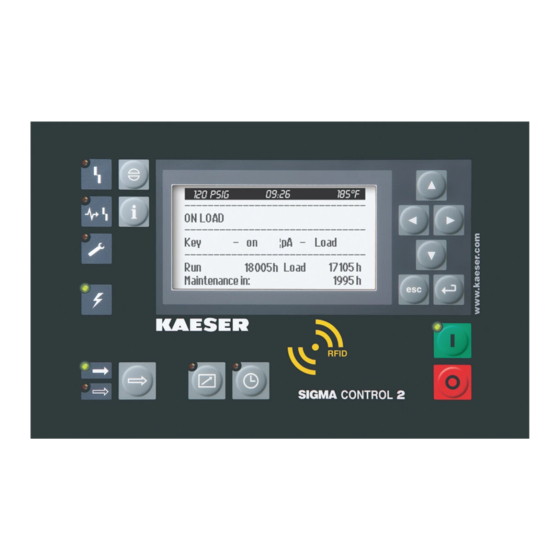
SIGMA CONTROL 2 Quick reference guide Operating elements 1 SIGMA CONTROL 2 Quick reference guide Operating elements Fig. 1 Operating elements Item Designation Function «Up» Scrolls the menu up. Increases a parameter value. «Left» Moves to the left. Moves the cursor position to the left. -
Page 14: Display Elements
SIGMA CONTROL 2 Quick reference guide Display elements Display elements Fig. 2 Display elements Item Designation Function Indicator illuminates in green when the machine is switched on. Display Graphic display with 8 lines and 30 characters per line. Time control Illuminates continuously in green when the machine is controlled by the timer. -
Page 15: Main Menu Overview
SIGMA CONTROL 2 Quick reference guide Main menu overview Main menu overview Use the «Enter» key to access the main menu. Menu no. Menu name Function Status Displays messages, statistics and status information Performance data Displays measured data from the machine and its components (e.g. -
Page 16: Tab. 4 Functions Overview
SIGMA CONTROL 2 Quick reference guide Functions overview Function Menu Action steps Chapter <Configuration – External DI / AII signal – Key remote – ☑> Activate the 8.2.13 «Remote control» key Activate – Activate «Remote control» key – Press the «Remote control»... -
Page 17: Regarding This Document Using This Document
The licenses can also be found under this address: http://www.gnu.org/licenses http://code.google.com/p/curve25519-donna/ Within three years from receipt of SIGMA CONTROL 2, you may obtain the complete source code of the copyright-protected software packages by sending a corresponding order to the following ad‐ dress: D&D Electrical Design... -
Page 18: Certification
➤ Please note the symbols and labels used in this document. 2.5.1 Warnings Warnings indicate danger potentially resulting in personal injury, if the measures specified are not taken. Service Manual Controller SIGMA CONTROL 2 BLOWER ≥ 4.0.X No.: 901700 14 E... -
Page 19: Potential Damage Warnings
Potential effects when ignoring the warning are indicated here. ➤ The protective measures against the damages are shown here. ➤ Carefully read and fully comply with warnings against damages. Service Manual Controller No.: 901700 14 E SIGMA CONTROL 2 BLOWER ≥ 4.0.X... -
Page 20: Other Alert Notes And Their Symbols
➤ ... as is a solution. This symbol identifies important information or measures regarding the protection of the envi‐ ronment. Further information Further subjects are introduced here. Service Manual Controller SIGMA CONTROL 2 BLOWER ≥ 4.0.X No.: 901700 14 E... -
Page 21: Technical Specifications 3.1 Controller Sigma Control 2
255 x 128 Width [mm] Height [mm] Maximum number of lines/characters 8/30 Colours Black/white with grey scale Lighting LED backlit px ≙ pixel Tab. 9 Display data Service Manual Controller No.: 901700 14 E SIGMA CONTROL 2 BLOWER ≥ 4.0.X... -
Page 22: Fig. 3 Mcs Interfaces
The positions of the interfaces X1–X6 are marked on the rear of the controller. Tab. 10 MCS interfaces Identification with RFID Equipment Card Characteristic Value Hardware on the SIGMA CONTROL 2 controller RFID reader Hardware (external) RFID Equipment Card Recognition distance [m] Max. 0.05 Frequency [MHz] 13.56... -
Page 23: Input/Output Module
Power is provided by the power supply unit within the machine. Characteristic Value Rated voltage (stabilised) [V DC] Current consump‐ tion SIGMA CONTROL 2 with IOM 1 [A] IOM ≙ Input/Output module Tab. 13 Power supply specifications 3.1.2.2 Maximum cable lengths... -
Page 24: Sensors
Value Sensing resistance (to DIN IEC 751) PT100 Connection Two-core Tab. 18 Resistance thermometer Communication modules SIGMA CONTROL 2 supports the following communication modules: ■ PROFIBUS (Option C41) ■ Modbus (Option C42) ■ DeviceNet (Option C43) ■ Modbus TCP (Option C44) ■... -
Page 25: Profibus Module
Value Controller SIGMA CONTROL 2 SIGMA AIR MANAGER 4.0 SIGMA CONTROL 2 or ASCII, RS485 or RS232, galvanically isolated Baud rate Adjustable, possible baud rates: [bps] 1200 / 2400 / 4800 / 9600 / 19200 / 38400 / 57600 / 76800 / 115200... -
Page 26: Modbus Tcp Module
7_9696_PA. Bold elements: Factory setting Tab. 21 Technical Specifications - SIGMA CONTROL 2 interface Assignment of the SIGMA CONTROL 2 interface The Modbus interface is galvanically isolated and features RS485 and RS2232 signals. To use the RS232 interface, connect Pin 2 with Pin 3. -
Page 27: Devicenet Module
Baud rate [kbps] Automatic recognition, possible baud rates: 125–500 Input data [bytes] Output data [bytes] 128 Data content “Technical description SIGMA CONTROL 2 process image“, document num‐ ber 7_7601xPA. Tab. 26 Technical data - DeviceNet communications module Service Manual Controller No.: 901700 14 E... -
Page 28: Profinet Module
Feature Value Controller SIGMA CONTROL 2 SIGMA AIR MANAGER 4.0 SIGMA CONTROL 2 device (Slave) with RT classification, conformity class B, topology detection (LLDP), network management (SNMP), redundancy, MRP protocol Connection 2x RJ45 ports (Cat5e), 2-port switch, potential isolation Baud... -
Page 29: Ethernet/Ip-Module
SIGMA CONTROL 2 process im‐ SIGMA AIR MANAGER 4.0 process im‐ age", document number age", document number 7_9696_PA. 7_7601xPA. Tab. 29 Technical Specifications - SIGMA CONTROL 2 interface Assignment of PROFINET interface Pin * Signal Conductor colour Description Yellow Send positive (positive transmit) TD–... -
Page 30: Tab. 32 Technical Data Ethernet/Ip-Interface
Conductor Network conductor, CAT5 shielded, CU, for example: 7.7629.0 Plug Bus plug RJ45, IP20, for example: 7.7628.1 Maximum cable length [m] Tab. 34 EtherNet/IP-Interface - Cabling recommendation Service Manual Controller SIGMA CONTROL 2 BLOWER ≥ 4.0.X No.: 901700 14 E... -
Page 31: Safety And Responsibility Basic Instructions
The safety regulations of the machine in which SIGMA CONTROL 2 is installed apply. Specified use SIGMA CONTROL 2 is solely intended for the control of machines in which SIGMA CONTROL 2 is factory-installed. Any other use is considered incorrect. The manufacturer is not liable for any dam‐... -
Page 32: Design And Function
All other sections apply to both machine types. The controller SIGMA CONTROL 2 controls, regulates, monitors, and protects the machine. All parameters needed to operate KAESER blowers can be set and displayed using the controller. Various user-dependent password mechanisms protect the parameters. -
Page 33: Fig. 4 System Structure
SIGMA CONTROL 2. The protective function allows: ■ Automatic machine shutdown on alarms that may lead to damage to the machine, e.g. overcur‐ rent, overpressure, overtemperature. Service Manual Controller No.: 901700 14 E SIGMA CONTROL 2 BLOWER ≥ 4.0.X... -
Page 34: Control Panel
Switches between LOAD and IDLE operating modes «Information» Display message memory. «Acknowledge» Confirms/acknowledges fault and warning messages. When permissible: Reset message history (RESET). not on SXC Tab. 35 Operating elements Service Manual Controller SIGMA CONTROL 2 BLOWER ≥ 4.0.X No.: 901700 14 E... -
Page 35: Indicator Elements
Fault Flashes red to indicate a fault with the machine. Illuminates continuously in red after message has been acknowl‐ edged. not on SXC Tab. 36 Display elements Service Manual Controller No.: 901700 14 E SIGMA CONTROL 2 BLOWER ≥ 4.0.X... -
Page 36: Rfid Reader
Placing a suitable transponder in front of the RFID reader of the controller will automatically acti‐ vate the communication between transponder and SIGMA CONTROL 2. A suitable transponder is the RFID Equipment Card. Two of them have been provided with the ma‐... -
Page 37: Operating Mode
The following parameters with their current values are displayed in line 8: ■ Time elapsed since the machine was activated ■ Time remaining to next scheduled maintenance for the machine Service Manual Controller No.: 901700 14 E SIGMA CONTROL 2 BLOWER ≥ 4.0.X... -
Page 38: Main Menu
The «Enter» key only takes effect upon the active line. In some lines, you can adjust more than one parameter. In this case, you must first select the specific parameter using the «Left» or «Right» keys. Service Manual Controller SIGMA CONTROL 2 BLOWER ≥ 4.0.X No.: 901700 14 E... -
Page 39: Activating Keys With Check Boxes
5.4.4 Activating keys with check boxes Certain keys in the SIGMA CONTROL 2 are locked by default. In order to unlock these keys, acti‐ vate the corresponding check boxes in the active line of the display. Firstly, press the «Enter» key to switch into Setting mode: The check box flashes. -
Page 40: Kaeser Connect
To do so, you must generate a one-time password (see Chapter 8.2.5). KAESER CONNECT does not require additional software for this purpose. The display language for KAESER CONNECT can be set independently of the language used in the SIGMA CONTROL 2. Fig. 9... -
Page 41: Menu Overview
■ Date display format ■ Time display format Backup Save data from SIGMA CONTROL 2 to a PC via KAESER CONNECT not on SXC Tab. 40 KAESER CONNECT functions Further information For accessing KAESER CONNECT, logging in and other procedures, please see Chapter 8.3. -
Page 42: Menu Structure
Statistics ■ DI/DO display ■ Current operating mode Status menu, please see ta‐ For details of the ble 42. Power switching with frequency converter (OFC/SFC) Screw blower Service Manual Controller SIGMA CONTROL 2 BLOWER ≥ 4.0.X No.: 901700 14 E... - Page 43 Filter transmission venting Electrical equipment Annual maintenance due on Configuration menu, please 5 Configuration For details of the see table 43. Power switching with frequency converter (OFC/SFC) Screw blower Service Manual Controller No.: 901700 14 E SIGMA CONTROL 2 BLOWER ≥ 4.0.X...
- Page 44 Block ■ Sound enclosure cooling ■ AFxM-valve ■ Aftercooler Components menu, please For details of the see table 46. Power switching with frequency converter (OFC/SFC) Screw blower Service Manual Controller SIGMA CONTROL 2 BLOWER ≥ 4.0.X No.: 901700 14 E...
-
Page 45: Tab. 41 Menu Structure Of Main Menu
Motor starts total since/Reset Motor starts /h Motor starts /d 1.3 DI/DO display 1st I/O module DI/DO display only visible in the event of parametrisation error Service Manual Controller No.: 901700 14 E SIGMA CONTROL 2 BLOWER ≥ 4.0.X... -
Page 46: Tab. 42 Status Menu
Date/Time Time zone ■ Time server ─ active: ─ IP address Date format Time format Pressure unit Temperature unit Display illumination Power switching with frequency converter (OFC/SFC) Service Manual Controller SIGMA CONTROL 2 BLOWER ≥ 4.0.X No.: 901700 14 E... - Page 47 Flow rate ─ v_min ─ v_max ─ local set value ─ Set value source ─ Reference Ramp up time Ramp down time: Power switching with frequency converter (OFC/SFC) Service Manual Controller No.: 901700 14 E SIGMA CONTROL 2 BLOWER ≥ 4.0.X...
-
Page 48: Tab. 43 Configuration Menu
External message 2 ─ External message 3 ■ Switch ─ ─ ─ ─ ─ ─ ─ block speed Power switching with frequency converter (OFC/SFC) Configuration menu Tab. 43 Service Manual Controller SIGMA CONTROL 2 BLOWER ≥ 4.0.X No.: 901700 14 E... -
Page 49: Tab. 44 Communication Menu
The following KAESER communications mod‐ ules may be used: ■ PROFIBUS ■ Modbus ■ Modbus TCP ■ DeviceNet ■ PROFINET ■ EtherNet/IP Communication menu Tab. 44 Service Manual Controller No.: 901700 14 E SIGMA CONTROL 2 BLOWER ≥ 4.0.X... -
Page 50: Tab. 45 Connections Menu
─ SAM 4.0 active: Send/Receive Send ─ IP address ─ Port ─ Communication error Start td Timeout Load signal Restart Timeout Cycle time Connections menu Tab. 45 Service Manual Controller SIGMA CONTROL 2 BLOWER ≥ 4.0.X No.: 901700 14 E... - Page 51 Motor temperature ─ Collection ─ ■ Greasing system ─ ─ ─ Interval ─ Target/Actual ─ Alarm ─ td/Actual Motor type Power switching with frequency converter (OFC/SFC) Screw blower Service Manual Controller No.: 901700 14 E SIGMA CONTROL 2 BLOWER ≥ 4.0.X...
- Page 52 ─ ─ ─ ─ n_ref, p ■ Speed monitoring ■ Vibration monitoring ─ VSE Status ─ ─ ↑ V1 Power switching with frequency converter (OFC/SFC) Screw blower Service Manual Controller SIGMA CONTROL 2 BLOWER ≥ 4.0.X No.: 901700 14 E...
-
Page 53: Control Modes
Screw blower Components menu Tab. 46 Control modes The behaviour of machines with SIGMA CONTROL 2 is determined by three software control modes interacting with each other. 5.8.1 Ready control mode The ready control mode specifies whether individual machines or machines under master control can be activated. -
Page 54: Operating Control
Tab. 47 SIGMA CONTROL 2 ready states When the operating voltage is applied to the SIGMA CONTROL 2 controller, the operating control is in OFF mode. If all faults are inactive, pressing «ON» produces the ON ready mode. If remote control is active, the remote load demand and remote idle demand signals are evaluated. - Page 55 IDLE The air generated by the compressor is vented into the atmosphere. The drive motor runs unloaded and consumes very little power. IDLE LED lights green. ■ Service Manual Controller No.: 901700 14 E SIGMA CONTROL 2 BLOWER ≥ 4.0.X...
- Page 56 5.8.2.1 Operating control without load/idle valve When the operating voltage is applied to SIGMA CONTROL 2, the operation control is in STOP operating mode and then switches to READY mode. Triggered by the Load run command, the drive motor starts via the MOTOR START operating mode and switches to LOAD operating mode.
- Page 57 The Stop command or the end of the shut-down switches the control to the STOP state. Service Manual Controller No.: 901700 14 E SIGMA CONTROL 2 BLOWER ≥ 4.0.X...
-
Page 58: Installation And Operating Conditions
Direct sunlight (UV radiation) can destroy the display screen. ➤ Do not allow the display screen to be subjected to direct sunlight. ➤ See the machine's operating manual for required conditions. Service Manual Controller SIGMA CONTROL 2 BLOWER ≥ 4.0.X No.: 901700 14 E... -
Page 59: Installation
Time control: Risk of injury caused by unexpected starting! ➤ Make sure the power supply disconnecting device is switched off before commencing any work on the machine. Tab. 50 Machine identification Service Manual Controller No.: 901700 14 E SIGMA CONTROL 2 BLOWER ≥ 4.0.X... -
Page 60: Initial Start-Up Outline
8 Initial Start-up Outline SIGMA CONTROL 2 was designed and developed for a number of applications. The settings that can be made are correspondingly varied. It is possible that only a few of these settings are needed for the initial start-up. This depends on the application. -
Page 61: Selecting A Menu Item
Menu items can be selected using the keys «Up», «Down» and «Enter». Example: Selecting the < Configuration – General > menu 1. Switch on the machine and wait for the SIGMA CONTROL 2 to start up. The operating display is shown. -
Page 62: Setting The Language
8 0 ° C Main menu Active line with current language ----------------English GB---------------- Submenu ▶1 Status Submenu ▶2 Performance data Submenu ▶3 Operating data Submenu ▶4 Maintenance Submenu ▶5 Configuration Service Manual Controller SIGMA CONTROL 2 BLOWER ≥ 4.0.X No.: 901700 14 E... -
Page 63: Noting The User Name
1. Note down the username (= RFID Equipment Card number). 2. Keep the note in a secure location. Should your RFID Equipment Card get damaged or lost: ➤ If you know your username and password, you can log in to the SIGMA CONTROL 2 manually (see chapter 8.2.5). 8.2.4 Logging in with an RFID Equipment Card The RFID Equipment Card allows quick and easy log-in to the SIGMA CONTROL 2. -
Page 64: Generating A Password
You have noted down your username and stored it in a suitable location (see chapter 8.2.3). The next step is to generate a password in the SIGMA CONTROL 2. Note down this password as well and store it a suitable location. With these two pieces of information to hand, you will be able to log in to the SIGMA CONTROL 2 manually in the event that your RFID Equipment Card is damaged or lost. -
Page 65: Logging In Manually
2. Using the «Up» or «Down» key, select the line 3. Press the «Enter» key. Setting mode is active. A column containing a selection of characters is displayed. The selected character flashes. Service Manual Controller No.: 901700 14 E SIGMA CONTROL 2 BLOWER ≥ 4.0.X... -
Page 66: Setting Up The Master Rfid Equipment Card
12. Press the «Enter» key. Current access level 2 is displayed. Result You are now logged in to the SIGMA CONTROL 2 with access level 2, via manual input of your username and password. 8.2.7 Setting up the master RFID Equipment Card If you are using the SIGMA CONTROL 2 controller to operate multiple KAESER machines, it may be a good idea to create a master RFID Equipment Card with which you can log into all of the ma‐... -
Page 67: Checking/Setting The Date And Time
See chapter 8.2.16. <Configuration – General> . 1. Open the menu 5.1 Date/Time . 2. Using the «Up» or «Down» key, select the line Service Manual Controller No.: 901700 14 E SIGMA CONTROL 2 BLOWER ≥ 4.0.X... - Page 68 00.00.00 . The day indicator flashes: 5. Use the «Up» or «Down» key to set the day. 6. Press the «Right» key. 00.00.00 . The month indicator flashes: Service Manual Controller SIGMA CONTROL 2 BLOWER ≥ 4.0.X No.: 901700 14 E...
-
Page 69: Setting The Time Zone
8.2.9 Setting the time zone The time zone in which the machine is to be operated must be set in the SIGMA CONTROL 2, so as to ensure a timely automatic changeover from winter time (standard time) to daylight saving time. -
Page 70: Tab. 52 Date Formats
01:33:45PM hh:mmAM/PM 01:33PM Tab. 53 Settings options for the time format Precondition Access level 2 is activated <Configuration – General> . 1. Open the menu 5.1 Service Manual Controller SIGMA CONTROL 2 BLOWER ≥ 4.0.X No.: 901700 14 E... -
Page 71: Tab. 54 Settings Options For The Pressure Units
0 8 : 1 5 A M 8 0 ° C Menu 5.1 General Time format hh:mm:ssAM/PM ······························ Unit of pressure Pressure unit Unit of temperature Temperature unit °C ······························ Display illumination Service Manual Controller No.: 901700 14 E SIGMA CONTROL 2 BLOWER ≥ 4.0.X... -
Page 72: Setting The Display Illumination
Set the display illumination mode: Mode Automatic Indicator Function Illumination is extin‐ Permanent setting Permanent setting guished after the Illumination "on" Illumination "off" timeout has elapsed Tab. 56 Display illumination Service Manual Controller SIGMA CONTROL 2 BLOWER ≥ 4.0.X No.: 901700 14 E... -
Page 73: Setting The Contrast And The Brightness
Contrast and brightness are set. 8.2.13 Activating the remote control The «remote control» key on the operating panel of the SIGMA CONTROL 2 can be activated or deactivated. Various menus offer check boxes for this setting. Precondition Access level 2 is activated. -
Page 74: Ip Configuration
8.2.14 IP configuration For the SIGMA CONTROL 2 to be connected to the network, you must set the IP configuration (for KAESER CONNECT for example). If you use SIGMA CONTROL 2 as the master control of two machines, you set other network IP configuration menu (see chapter 8.7.4). -
Page 75: Tab. 57 Network Parameters
Example address DNS Server 1 008.008.008.008 Example address DNS Server 2 008.008.004.004 Active line Restart network ☐ 12. Press «Enter». The check box Restart network will flash. Service Manual Controller No.: 901700 14 E SIGMA CONTROL 2 BLOWER ≥ 4.0.X... -
Page 76: Setting The E-Mail Function
The network is restarted. The set network parameters are active. 8.2.15 Setting the e-mail function SIGMA CONTROL 2 is able to send messages via e-mail. For this purpose, a network connection with an SMTP server is required. Setting e-mail parameters Precondition Access level 2 is activated. - Page 77 Setting the controller 6. Set the e-mail parameters as described above: If SIGMA CONTROL 2 is connected via SIGMA NETWORK to SAM 4.0 and emails are to be SMTP forwarded via SAM 4.0, then enter the IP address of interface X6 of SAM 4.0 in the server: field.
-
Page 78: Setting The Time Server
8.2.16 Setting the time server If SIGMA CONTROL 2 is connected to the network, you can set the access to an SNTP server available in the Internet or a local Intranet. SIGMA CONTROL 2 then automatically imports the date and time settings and ensures continuous synchronisation of the internal clock with the exter‐... -
Page 79: Kaeser Connect Benefits
12. Press «Escape» repeatedly to leave this menu. Result Access to the selected time server is active. The internal clock of SIGMA CONTROL 2 is permanently synchronised. KAESER CONNECT benefits Using an Internet-capable device with web browser, you can use KAESER CONNECT to remotely display these SIGMA CONTROL 2 menus: ■... -
Page 80: Open Kaeser Connect
The user name (see chapter 8.2.3) and password (see chapter 8.2.5) are known. The controller's IP address is known, see chapters 8.2.14 and 8.7.4. 1. Use an Ethernet cable to connect SIGMA CONTROL 2 to the Internet-capable device or net‐ work. -
Page 81: System Status Menu
7. Click to set the selected language Result KAESER CONNECT is displayed in the set language. 8.3.2 System status menu Precondition KAESER CONNECT for SIGMA CONTROL 2 is displayed. Service Manual Controller No.: 901700 14 E SIGMA CONTROL 2 BLOWER ≥ 4.0.X... -
Page 82: Fig. 19 System Status Menu
Initial Start-up KAESER CONNECT benefits System status menu Fig. 19 System status menu element. 1. Click the System status menu is displayed Fig. 20 Main menu Service Manual Controller SIGMA CONTROL 2 BLOWER ≥ 4.0.X No.: 901700 14 E... -
Page 83: Graphs Menu
Initial Start-up KAESER CONNECT benefits 2. Click in the SIGMA CONTROL 2 display. The Main menu is displayed. 3. Click the numbered lines. The system displays the corresponding sub-menus. 4. Press ESC repeatedly to leave this menu. 8.3.3 Graphs menu... -
Page 84: Fig. 22 Control Keys
An SD card with sufficient free memory is inserted in the X5 SD card slot The SD card was inserted for the entire operating time of the machine. The SIGMA CONTROL 2 data recorder function is activated. Start: . 1. Enter the date and time for the start time in the required time period in End: . -
Page 85: Messages Menu
■ Blower messages ■ System messages ■ Diagnostic messages Precondition KAESER CONNECT for SIGMA CONTROL 2 is displayed. Messages (illustration similar) Fig. 23 Messages menu element. 1. Click the Messages menu is displayed 2. Click the required message type. 3. Check messages. -
Page 86: User Management Menu
User name: 6 to 16 characters, the second character must not be a number ■ Password: 6 to 16 characters Precondition The generated password is available. KAESER CONNECT for SIGMA CONTROL 2 is displayed. Service Manual Controller SIGMA CONTROL 2 BLOWER ≥ 4.0.X No.: 901700 14 E... -
Page 87: Fig. 25 User Management Menu
Log on for write access: window User name: field. 3. Enter your user name in the Password: field. 4. Enter your password in the 5. Click OK. User management menu is displayed Service Manual Controller No.: 901700 14 E SIGMA CONTROL 2 BLOWER ≥ 4.0.X... -
Page 88: Fig. 27 User Management Menu
1. Click the required user account in the list. Password: field. 2. Enter a new password in the Repeat password: field. 3. Re-enter the same new password in the 4. Click Update user. Service Manual Controller SIGMA CONTROL 2 BLOWER ≥ 4.0.X No.: 901700 14 E... -
Page 89: Settings Menu
Settings menu Fig. 28 For example, you want to convert your units to US values: Precondition KAESER CONNECT for SIGMA CONTROL 2 is displayed. 1. Click the Settings menu element. 2. Click the arrow key for the unit of pressure. -
Page 90: Save Data Menu
Initial Start-up KAESER CONNECT benefits 8.3.8 Save data menu Backup menu allows you to download data from SIGMA CONTROL 2 to the Internet-capable device. The following backup types are available: ■ Backup all ■ Log files ■ Settings ■ User information Precondition KAESER CONNECT for SIGMA CONTROL 2 is displayed. -
Page 91: Kaeser Connect Exit
The downloaded data can be sent to an authorised service partner for the purposes of evaluation and service support. 8.3.10 KAESER CONNECT exit In order to close KAESER CONNECTfor SIGMA CONTROL 2, click Logout in the header. ➤ Click Logout. Result The system displays a message confirming the successful logout. -
Page 92: Displaying And Setting The Blower Properties
The installation elevation can be set within certain limits: Precondition Access level 2 is activated. 1. Open the 5.2 <Configuration – Blower properties> menu. Altitude line. 2. Use «Up» or «Down» to select the Service Manual Controller SIGMA CONTROL 2 BLOWER ≥ 4.0.X No.: 901700 14 E... -
Page 93: Machine Start And Machine Stop
Automatic start/stop in timer mode Overview Time control ■ Select menu ■ Set clock program ■ Activating time control 8.5.1.1 Select the Time control menu Precondition Access level 2 is activated. Service Manual Controller No.: 901700 14 E SIGMA CONTROL 2 BLOWER ≥ 4.0.X... -
Page 94: Tab. 62 User-Defined Clock Programme Machine On/Off
All current switching points are reset Reset ☐ ······························ Active line n.a. 00:00AM n.a. 00:00AM n.a. 00:00AM User-defined clock program No.: Time Function Tab. 62 User-defined clock programme machine ON/OFF Service Manual Controller SIGMA CONTROL 2 BLOWER ≥ 4.0.X No.: 901700 14 E... -
Page 95: Tab. 63 Example Of A Machine On/Off Clock Program
3. Press «Enter». n.a. indication flashes. 4. Use «Up» or «Down» to set the weekdays. 5. Press the «Enter» key. The setting is applied. 6. Press the «Right» key. Service Manual Controller No.: 901700 14 E SIGMA CONTROL 2 BLOWER ≥ 4.0.X... - Page 96 ☐ ······························ Switching point 01: Mon-Fri 06:30AM Switching point 02 Mon-Fri 12:00PM Switching point 03 Mon-Fri 01:00PM 3. Press the «Up» key. The check box is activated. Service Manual Controller SIGMA CONTROL 2 BLOWER ≥ 4.0.X No.: 901700 14 E...
-
Page 97: Automatic Start/Stop With Timer
Precondition The «Time control» key is activated; see chapter 8.5.1.3. ➤ Press the «Time control» key on the SIGMA CONTROL 2 operating panel to activate the time control. Time control LED on the operating panel of the SIGMA CONTROL 2 signalises with green Result continuous light that the machine is operated with activated time control. -
Page 98: Automatic Restart" Function
The first machine may start immediately and does not require a delay time. Machine number Start time [sec] Delay time [sec] –– –– Service Manual Controller SIGMA CONTROL 2 BLOWER ≥ 4.0.X No.: 901700 14 E... -
Page 99: Tab. 64 Delay Time For Automatic Restart
5. Press the «Enter» key. The setting is applied. Result You have adjusted the delay tome for the restart after a power supply failure from 1 s to 10 s. Service Manual Controller No.: 901700 14 E SIGMA CONTROL 2 BLOWER ≥ 4.0.X... -
Page 100: Controlling The Machine Remotely
If required, activate the «Time control» key and configure the time programme (see Chap‐ ter 8.5.1.2) ■ Activating the remote control ON LED illuminates green. ■ Press the «ON» key. The Two methods are available for starting the machine remotely: Service Manual Controller SIGMA CONTROL 2 BLOWER ≥ 4.0.X No.: 901700 14 E... - Page 101 7. Press the «Right» key. 8. Press the «Enter» key. The check box assigned to the input flashes. 9. Press the «Up» key. The check box is activated. Service Manual Controller No.: 901700 14 E SIGMA CONTROL 2 BLOWER ≥ 4.0.X...
- Page 102 7. Press the «Right» key. 8. Press the «Enter» key. The check box assigned to the input flashes. 9. Press the «Up» key. The check box is activated. Service Manual Controller SIGMA CONTROL 2 BLOWER ≥ 4.0.X No.: 901700 14 E...
- Page 103 7. Press the «Right» key. 8. Press the «Enter» key. The check box assigned to the input flashes. 9. Press the «Up» key. The check box is activated. Service Manual Controller No.: 901700 14 E SIGMA CONTROL 2 BLOWER ≥ 4.0.X...
-
Page 104: Operating Modes In Frequency-Controlled Machines
Activating the remote control ➤ Activate remote control see chapter 8.2.13. Result SIGMA CONTROL 2 remote control is activated. Operating modes in frequency-controlled machines Various operating modes are available in frequency-controlled machines. Operating modes are se‐ Operating modes . The options available for the operating modes are de‐... -
Page 105: Current Signal Aii1.02
Precondition Access level 2 is activated. The operating mode is displayed. Fixed speed or Pressure control mode is set in the 5.4 <Configuration – Operating modes> menu. Service Manual Controller No.: 901700 14 E SIGMA CONTROL 2 BLOWER ≥ 4.0.X... -
Page 106: Setting The Operating Mode
The setting mode is active. The currently set language flashes. 4. Use «Up» or «Down» to set the required operating mode. 5. Press «Enter». The setting is applied. Service Manual Controller SIGMA CONTROL 2 BLOWER ≥ 4.0.X No.: 901700 14 E... -
Page 107: Constant Speed
4. Press «Enter». The setting is applied. ▶1Fixed speed line. 5. Use «Up» or «Down» to select the 6. Press «Enter». Fixed speed menu is displayed. The 5.4.1 Service Manual Controller No.: 901700 14 E SIGMA CONTROL 2 BLOWER ≥ 4.0.X... -
Page 108: Pressure Control
Access level 2 is activated. <Configuration – Operating modes – Pressure control> menu. 1. Open the 5.4.2 2. Use «Up» or «Down» to select the Source actual pressure line. Service Manual Controller SIGMA CONTROL 2 BLOWER ≥ 4.0.X No.: 901700 14 E... - Page 109 Local set pressure 1.0bar 1.0rpm / mbar 1.00rpm / (mbar *s) Set pressure rise time Local set pressure . 4. Use «Up» or «Down» to set the value for Service Manual Controller No.: 901700 14 E SIGMA CONTROL 2 BLOWER ≥ 4.0.X...
- Page 110 PI controller and is performed empirically. Precondition Access level 2 is activated. Starting value KP: 0.1 rpm / mbar Starting value KI: 0.01 rpm / (mbar *s) Service Manual Controller SIGMA CONTROL 2 BLOWER ≥ 4.0.X No.: 901700 14 E...
-
Page 111: External Speed Definition
Current signal AII1.02 menu to set the scaling of the 4–20 mA signal. The galvanic Use the 5.5.1 decoupling of the signal is performed via a buffer amplifier installed in the control cabinet. Service Manual Controller No.: 901700 14 E SIGMA CONTROL 2 BLOWER ≥ 4.0.X... -
Page 112: Controlling Via An External Variable
, the following operating modes are available: In addition to ■ xA (permanently) ■ xB (permanently) Service Manual Controller SIGMA CONTROL 2 BLOWER ≥ 4.0.X No.: 901700 14 E... - Page 113 Ramp up time External values control . 3. Using the «Up» or «Down» key, set the operating mode 4. Press the «Enter» key. The setting is applied accordingly. Service Manual Controller No.: 901700 14 E SIGMA CONTROL 2 BLOWER ≥ 4.0.X...
- Page 114 10rpm/s/% Set value Actual value Set value ramp-up time Pressure control for the set‐ 2. Set the control parameters for the PI controller. See chapter 8.6.4 ting. Service Manual Controller SIGMA CONTROL 2 BLOWER ≥ 4.0.X No.: 901700 14 E...
-
Page 115: Flow Rate Control
This always refers to the intake volume. As a reference, the flow rate can be based on either inlet conditions or standard conditions. The SIGMA CONTROL 2 calculates the flow rate from the airend speed, with the aid of measured values and machine-dependent parameters. -
Page 116: Sfc Acceleration Time
Ramp up time is the time from minimum speed to reaching the machine-specific maximum speed. The values for Ramp up time and Ramp down time: which can be set at SIGMA CONTROL 2 are added to the similar parameters that have already been set in the FC. -
Page 117: Setting The Machine For Master Control Operation
The controller offers several possibilities to work together with other controllers: Method Description Section SIGMA AIR You must modify the settings in SIGMA CONTROL 2 for the op‐ 8.7.2 MANAGER 4.0 mode eration via SIGMA NETWORK using the KAESER SIGMA AIR MANAGEMENT SYSTEM (SIGMA AIR MANAGER 4.0). -
Page 118: Sam 4.0 Mode
Timer control (lowest priority) 8.7.2 SAM 4.0 mode You must modify the settings in SIGMA CONTROL 2 for the operation via SIGMA NETWORK us‐ ing, for example, the KAESER SIGMA AIR MANAGER 4.0 (SAM 4.0). Precondition SIGMA CONTROL 2 is connected to SAM 4.0 via SIGMA NETWORK and ready for operation (see the SAM 4.0 operating manual in the chapter “Installation”) - Page 119 8.1.2.2 SAM 4.0 IP address 169.254.100.100 Port 2000 ······························ Communication error : ☑ active line Start td: Timeout : ☑ 11. Press «Enter». The setting mode is active. Service Manual Controller No.: 901700 14 E SIGMA CONTROL 2 BLOWER ≥ 4.0.X...
- Page 120 For the communication with SAM 4.0, the value of Start td must be set to 30 s. SIGMA CONTROL 2 can monitor the bus communication at user level. For this purpose, the bus master reads a value ("toggle bit") that changes with every bus cycle and returns it without change.
-
Page 121: Interconnected Operation Via A Communications Module
In either case, the communi‐ cations module must be set for the respective application in the menu of the SIGMA CONTROL 2. The SIGMA CONTROL 2 supports the following KAESER communications modules: ■... -
Page 122: Tab. 68 Setting The Starttd Parameter
For this purpose, the bus master reads a value ("toggle bit") that changes with every bus cycle and returns it without change. SIGMA CONTROL 2 returns a bus alarm if the Timeout ). Activate monitoring by setting a check bit does not change for a time longer than set ( mark ☑. -
Page 123: Tab. 70 Setting The Starttd Parameter
For this purpose, the bus master reads a value ("toggle bit") that changes with every bus cycle and returns it without change. SIGMA CONTROL 2 returns a bus alarm if the Timeout ). Activate the check box to enable monitor‐... -
Page 124: Tab. 71 Setting The Timeout Parameter
Type line. and displays it in the 3. Select the data exchange direction: ► SIGMA CONTROL 2 ⇆ Bus master (SIGMA CONTROL 2 sends process data and receives Send/Receive or Master : Set Com module . control data): Send or ►... -
Page 125: Tab. 72 Setting The Starttd Parameter
For this purpose, the bus master reads a value ("toggle bit") that changes with every bus cycle and returns it without change. SIGMA CONTROL 2 returns a bus alarm if the Timeout ). Activate the check box to enable monitor‐... -
Page 126: Tab. 74 Setting The Starttd Parameter
For this purpose, the bus master reads a value ("toggle bit") that changes with every bus cycle and returns it without change. SIGMA CONTROL 2 returns a bus alarm if the Timeout ). Activate the check box to enable monitor‐... -
Page 127: Tab. 76 Setting The Starttd Parameter
For this purpose, the bus master reads a value ("toggle bit") that changes with every bus cycle and returns it without change. SIGMA CONTROL 2 returns a bus alarm if the Timeout ). Activate the check box to enable monitor‐... -
Page 128: Tab. 77 Setting The Timeout Parameter
Type line. and displays it in the 3. Select the data exchange direction: ► SIGMA CONTROL 2 ⇆ Bus master (SIGMA CONTROL 2 sends process data and receives Send/Receive or Master : Set Com module . control data): Send or ►... -
Page 129: Master Control Of Two Machines In Master/Slave Operation
For this purpose, the bus master reads a value ("toggle bit") that changes with every bus cycle and returns it without change. SIGMA CONTROL 2 returns a bus alarm if the Timeout ). Activate the check box to enable monitor‐... -
Page 130: Fig. 31 Direct Connection Of Two Sigma Control 2
■ SIGMA NETWORK cable (7.9679.0) or Ethernet cable with a maximum connection length of 100 m each ■ For each machine with SIGMA CONTROL 2: ─ Retrofit kit LAN RJ45 (7.5250.01870) ■ For connecting the machines to a network (LAN) or switch: ─... - Page 131 24V range (blue wiring) of the ducts. 3. Attach the RJ45-plug to the cable end. 4. Plug the RJ45 plug into the Ethernet interface X1 of the SIGMA CONTROL 2 until it latches. For connecting the machines to a network (LAN) or switch: Connect the Ethernet cable for each machine to the LAN connection or switch.
- Page 132 8 0 ° C Menu 8.1.2.1 SIGMA CONTROL 2 Status 1¦Error ------------------------------ Active line Mode Slave Port 2.001 ······························ Communication partner 6. Press the «Enter» key. The setting is applied. Service Manual Controller SIGMA CONTROL 2 BLOWER ≥ 4.0.X No.: 901700 14 E...
- Page 133 8 0 ° C 4.2 Load balancing Active line with inactive check box Load balancing ☐ dt maintenance hours Maintenance Master Maintenance Slave Master state ready Slave state ready Service Manual Controller No.: 901700 14 E SIGMA CONTROL 2 BLOWER ≥ 4.0.X...
-
Page 134: Setting Input And Output Signals
Controller is powered up ON LOAD The machine is running in LOAD mode Collective error Fault has occurred Collective warning Warning message has appeared Tab. 81 Assigned output signals Service Manual Controller SIGMA CONTROL 2 BLOWER ≥ 4.0.X No.: 901700 14 E... - Page 135 If the message is correctly assigned to the output and activated, Logic option. 10. If necessary, set the Result A message about the operational state is now sent via the assigned digital output. Service Manual Controller No.: 901700 14 E SIGMA CONTROL 2 BLOWER ≥ 4.0.X...
-
Page 136: Output Input Signals On The Display
8.8.2.2 Enter the message text External message 1 . In the below example we select External message 1 line. 1. Use «Up» or «Down» to select the Service Manual Controller SIGMA CONTROL 2 BLOWER ≥ 4.0.X No.: 901700 14 E... - Page 137 0s ¦ Logic : DOR1.04 ☐ Message type (operational, alarm, warning) Warning ☑ 5. Press the «Right» key. 6. Press «Enter». The check box assigned to the input flashes. Service Manual Controller No.: 901700 14 E SIGMA CONTROL 2 BLOWER ≥ 4.0.X...
-
Page 138: Tab. 82 Logic Settings
Result 8.8.2.5 Setting the logic Possible logic settings Message at Sign 24 V Tab. 82 Logic settings td line. 1. Use «Up» or «Down» to select the Service Manual Controller SIGMA CONTROL 2 BLOWER ≥ 4.0.X No.: 901700 14 E... - Page 139 1. Use «Up» or «Down» to select the DOR line. 2. Press «Enter». DOR output display flashes. 3. Select the output with the «Up» and «Down» keys. Service Manual Controller No.: 901700 14 E SIGMA CONTROL 2 BLOWER ≥ 4.0.X...
-
Page 140: Switching And/Or Triggering Messages With Thresholds
Threshold for the airend speed 0096 O/W/A block speed Power switching with frequency converter (OFC/SFC) Tab. 83 Available measured values p1 . Example: Setting for the inlet pressure Service Manual Controller SIGMA CONTROL 2 BLOWER ≥ 4.0.X No.: 901700 14 E... - Page 141 SD switching differential in the same way. 5. If necessary, adjust the value for the SP switching point and the SD switching differential are set. Result The threshold for the Service Manual Controller No.: 901700 14 E SIGMA CONTROL 2 BLOWER ≥ 4.0.X...
- Page 142 ☐ 5. Press the «Right» key. 6. Press «Enter». The check box assigned to the output flashes. 7. Press the «Up» key. The check box is activated. Service Manual Controller SIGMA CONTROL 2 BLOWER ≥ 4.0.X No.: 901700 14 E...
- Page 143 −0.2bar Delay (td) and logic 120s ¦ Logic Output DOR DOR1.03 ok ☑ Output DOT DOT1.01 ☐ 3. Press the «Up» key. The check box is activated. Service Manual Controller No.: 901700 14 E SIGMA CONTROL 2 BLOWER ≥ 4.0.X...
-
Page 144: Activating Remote Acknowledgement
Electric connection via DI 1.045– terminal -X15: 7+8 is made Access level 2 is activated. The operating mode is displayed. <Configuration – External DI / AII signal> menu. 1. Open the 5.5 Service Manual Controller SIGMA CONTROL 2 BLOWER ≥ 4.0.X No.: 901700 14 E... - Page 145 ➤ Activate remote control see chapter 8.2.13. Result The remote control is activated. Result Should a message occur, it can now be acknowledged from a control centre. Service Manual Controller No.: 901700 14 E SIGMA CONTROL 2 BLOWER ≥ 4.0.X...
-
Page 146: Error Behaviour
➤ The settings for Com-Module are carried out in the same manner. Service Manual Controller SIGMA CONTROL 2 BLOWER ≥ 4.0.X No.: 901700 14 E... -
Page 147: Commissioning The Machine
The operating mode is mapped as a pipe and instrument diagram on the display. Fig. 32 Operating mode 2. Continue the commissioning process as described in chapter "Commissioning" of the ma‐ chine's operating manual. Service Manual Controller No.: 901700 14 E SIGMA CONTROL 2 BLOWER ≥ 4.0.X... -
Page 148: Operation
The ambient conditions as described in Chapter "Installation and Operating Conditions" are met 1. Switch on the user's power supply isolating device. 2. Switch on the machine and wait for SIGMA CONTROL 2 to start. voltage applied to controller LED lights green. -
Page 149: Switching Off
Result The EMERGENCY STOP command device remains latched after actuation. The machine is secured against an automatic restart. Service Manual Controller No.: 901700 14 E SIGMA CONTROL 2 BLOWER ≥ 4.0.X... -
Page 150: Acknowledging Alarm And Warning Messages
Warning LED (yellow) Alarm LED (red) «Acknowledge» key Fault message A fault message shuts the machine down automatically. Fault LED flashes. The red Precondition The fault has been rectified Service Manual Controller SIGMA CONTROL 2 BLOWER ≥ 4.0.X No.: 901700 14 E... -
Page 151: Displaying Messages
Selected submenu: ■ Blower messages ■ Diagnostic messages ■ System messages Segment: ■ Message number ■ Type of message ■ Message status ■ Message date ■ Message time Service Manual Controller No.: 901700 14 E SIGMA CONTROL 2 BLOWER ≥ 4.0.X... -
Page 152: Status - Messages Menu
1.1 Messages active line ▶1 Current messages ▶2 Messages history ▶3 Address error ------------------------------ Number of currently registered faults current Alarms Number of currently registered warnings Warnings Service Manual Controller SIGMA CONTROL 2 BLOWER ≥ 4.0.X No.: 901700 14 E... - Page 153 Message text for message 0015 Bus alarm 0005 W c 04/16/22 08:15:37AM Message text for message 0005 T1 ↑ 3. Press «Escape» repeatedly to leave this menu. Service Manual Controller No.: 901700 14 E SIGMA CONTROL 2 BLOWER ≥ 4.0.X...
-
Page 154: Displaying Analogue Data
─ Current ─ DC link voltage DC link voltage ─ Torque Displaying analogue data Precondition The operating mode is displayed. <Performance data> menu. 1. Open the 2 Service Manual Controller SIGMA CONTROL 2 BLOWER ≥ 4.0.X No.: 901700 14 E... -
Page 155: Displaying Operating Data
─ Motor : Running time of drive motor (adjustable) ─ Block : Running time of blower block (adjustable) ─ SIGMA CONTROL 2 : Controller running time ─ OFC/SFC : FC block drive: Running time of the frequency converter ─ ■... - Page 156 The setting is applied accordingly. 6. Press the «Escape» key repeatedly to exit the menu. 0 h . Result The operating hours for the new drive motor are set to Service Manual Controller SIGMA CONTROL 2 BLOWER ≥ 4.0.X No.: 901700 14 E...
-
Page 157: Kwh Counter
To this end, the pulse output of the power meter is connected to a free digital input for the SIGMA CONTROL 2. Pulses sent to this digital input can be added up by a counter in the menu 3.3. Each pulse increases the meter reading by 1 kWh. The meter reading can be reset via the menu. -
Page 158: External Maintenance Counter
Set text for a maintenance counter Precondition Access level 2 is activated The operation display is shown Maintenance . 1. Open the menu 4 Service Manual Controller SIGMA CONTROL 2 BLOWER ≥ 4.0.X No.: 901700 14 E... - Page 159 The text is entered. Activate maintenance counter External counter 1 , for example. 1. Using the «Up» or «Down» key, select the line 2. Press the «Down» key once. Service Manual Controller No.: 901700 14 E SIGMA CONTROL 2 BLOWER ≥ 4.0.X...
- Page 160 Keep the «Up» or «Down» key pressed to change the maintenance interval in increments of 10, 100 or 1000. 5. Press the «Enter» key. The setting is applied accordingly. Result The maintenance interval is set. Service Manual Controller SIGMA CONTROL 2 BLOWER ≥ 4.0.X No.: 901700 14 E...
-
Page 161: Communication Modules
The communication module features LEDs providing information about the module status. Fig. 37 Modbus communication module – LEDs and interface Communications module LED DS: Device Status LED Common rail system: Communication Sub-D port, 9 poles Service Manual Controller No.: 901700 14 E SIGMA CONTROL 2 BLOWER ≥ 4.0.X... -
Page 162: Displays At The Modbus Tcp Module
Monitoring time exceeded (time-out) Module without voltage Green illuminates continuously Module in operation illuminates continuously Internal fault, module in "EXCEPTION" status flashes Fault in diagnostic object or IP address conflict Service Manual Controller SIGMA CONTROL 2 BLOWER ≥ 4.0.X No.: 901700 14 E... -
Page 163: Display At The Devicenet Module
Self test Tab. 93 DeviceNet communications module – Interpretation of LEDs 9.9.5 Displays at the PROFINET module The communication module features LEDs providing information about the module status. Service Manual Controller No.: 901700 14 E SIGMA CONTROL 2 BLOWER ≥ 4.0.X... -
Page 164: Fig. 40 Profinet Communication Module - Leds And Interface
4:1 (on:off) Internal error No connection. Green illuminates continuously Connection established, no communication flashes Communication in operation Tab. 94 PROFINET communications module – Interpretation of LEDs Service Manual Controller SIGMA CONTROL 2 BLOWER ≥ 4.0.X No.: 901700 14 E... -
Page 165: Save Data
Communication running, 10 Mbit/s Tab. 95 EtherNet/IP communication module – Interpretation of LEDs 9.10 Save data SIGMA CONTROL 2 settings can be backed up to an SD card. Service Manual Controller No.: 901700 14 E SIGMA CONTROL 2 BLOWER ≥ 4.0.X... - Page 166 Precondition An SD card with compatible file system (FAT32) and minimum 50 MB free memory is plugged into the SD card slot X5 of SIGMA CONTROL 2 The write protection of the SD card has been deactivated. Access level 2 is activated.
-
Page 167: Format Sd Card
Status recognised ······························ Active line Format SD card : ☑ 5. Press the «Enter» key. A security query is displayed. 6. Press «Enter». SD card being formatted. Service Manual Controller No.: 901700 14 E SIGMA CONTROL 2 BLOWER ≥ 4.0.X... -
Page 168: 10 Fault Recognition And Rectification
10.1 Basic information The following tables are intended to assist in locating the causes of faults. There are three types of fault indicated in the SIGMA CONTROL 2: ■ Fault with the machine: red LED flashes, the machine shuts down: see chapters 10.2 and 10.5. - Page 169 Check function of sound enclosure fan. 0014 A Sound enclosure tempera‐ Check function of machine heating sys‐ T_S ⇟ ture too low. tem. Keep ambient conditions within specified limits. Service Manual Controller No.: 901700 14 E SIGMA CONTROL 2 BLOWER ≥ 4.0.X...
- Page 170 Error while activating FC Contact an authorised service partner. Error FC ramp up 0031 A Frequency converter fault Contact an authorised service partner. Motor: n min not reached Service Manual Controller SIGMA CONTROL 2 BLOWER ≥ 4.0.X No.: 901700 14 E...
- Page 171 Contact an authorised service partner. Vibration monitoring VSE toring ⇞ 0092 A Switch p1 0093 A Switch p2 0094 A Switch T1 0095 A Switch T2 0096 A Switch block speed Service Manual Controller No.: 901700 14 E SIGMA CONTROL 2 BLOWER ≥ 4.0.X...
-
Page 172: Interpreting Warning Messages
Add in the meaning for the message text you have defined (see chapter 8.8). Message Possible cause Remedy 0001 W Equipment number not entered, or en‐ Contact an authorised service Equipment number tered incompletely. partner. incomplete Service Manual Controller SIGMA CONTROL 2 BLOWER ≥ 4.0.X No.: 901700 14 E... - Page 173 Bus link via Com module interface in‐ Check bus lines and plug. Com-Module terrupted. communication error 0016 W Oil temperature T3 too low Check ambient conditions. T3 ↓ Service Manual Controller No.: 901700 14 E SIGMA CONTROL 2 BLOWER ≥ 4.0.X...
- Page 174 Pressure peaks in vacuum network Check operating conditions Drag indicator p1 ⇟ 0039W Pressure peaks in compressed air net‐ Check operating conditions. Drag indicator p2 ⇞ work Service Manual Controller SIGMA CONTROL 2 BLOWER ≥ 4.0.X No.: 901700 14 E...
- Page 175 Deactivate service mode in FC service mode service mode 10.1.1.3 menu activated 0200 W Lubricating oil: Change the lubricating oil. Change lube h ↑ Maintenance interval expired. Service Manual Controller No.: 901700 14 E SIGMA CONTROL 2 BLOWER ≥ 4.0.X...
- Page 176 AII%d.0%d - open circuit alogue input. connection. 0869 W Short circuit in line for ext. sensor at Check line paths and sensor AII%d.0%d - short-circuit analogue input. connection. Service Manual Controller SIGMA CONTROL 2 BLOWER ≥ 4.0.X No.: 901700 14 E...
-
Page 177: Interpreting Operating Messages
Power OFF → ON 0038 O Pressure peaks in the vacuum network Drag indicator p1 ⇟ 0039 O Pressure peaks in the compressed air network Drag indicator p2 ⇞ Service Manual Controller No.: 901700 14 E SIGMA CONTROL 2 BLOWER ≥ 4.0.X... -
Page 178: Interpreting Diagnostic Messages
2 RFID Equipment Cards successfully registered Tab. 98 Operating messages 10.5 Interpreting diagnostic messages A diagnostic message shuts the machine down. Diagnostic messages are identified with the letter D. Service Manual Controller SIGMA CONTROL 2 BLOWER ≥ 4.0.X No.: 901700 14 E... -
Page 179: Interpreting System Messages
10.7.1.1 Machine and SIGMA CONTROL 2 In the event of a bus communications fault, the red “Communication” LED and the yellow “Warning” LED will flash on the SIGMA CONTROL 2. The following warning messages will be displayed: Message Possible cause... -
Page 180: Troubleshooting The Modbus Module
10.7.2.1 Machine and SIGMA CONTROL 2 In the event of a bus communications fault, the red “Communication” LED and the yellow “Warning” LED will flash on the SIGMA CONTROL 2. The following warning messages will be displayed: Message Possible cause... -
Page 181: Troubleshooting The Modbus Tcp/Ethernet Ip Module
10.7.3.1 Machine and SIGMA CONTROL 2 In the event of a bus communications fault, the red “Communication” LED and the yellow “Warning” LED will flash on the SIGMA CONTROL 2. The following warning messages will be displayed: Message Possible cause... -
Page 182: Troubleshooting The Devicenet Module
10.7.4.1 Machine and SIGMA CONTROL 2 In the event of a bus communications fault, the red “Communication” LED and the yellow “Warning” LED will flash on the SIGMA CONTROL 2. The following warning messages will be displayed: Message Possible cause... - Page 183 Slave address in module Set the slave address in the incorrect. SIGMA CONTROL 2 as parametrised in the bus master. For setting, see chapter 8. Internal software Defective module. Contact an authorised service partner. error COM Module Module not activated.
-
Page 184: Troubleshooting The Profinet Module
10.7.5.1 Machine and SIGMA CONTROL 2 In the event of a bus communications fault, the red “Communication” LED and the yellow “Warning” LED will flash on the SIGMA CONTROL 2. The following warning messages will be displayed: Message Possible cause... -
Page 185: 11 Maintenance
When the battery is discharged, the date and time of the controller will always re‐ set to 01/01/1970 at 01:00:00 in the Europe/Berlin time zone. Service Manual Controller No.: 901700 14 E SIGMA CONTROL 2 BLOWER ≥ 4.0.X... -
Page 186: 12 Spares, Operating Materials, Service
▶2 Blower package ▶3 IO modules ▶4 FC information 3. Press «Enter». 5.1.1.1 SIGMA CONTROL 2 - MCS menu is displayed. Header 4 0 0 m b a r 0 8 : 1 5 A M 8 0 ° C Menu 5.1.1.1 SIGMA CONTROL 2 - MCS... - Page 187 3. Option K2/K9: Detach the user connecting lines and use compressed air (<2 bar) to blow out the cooling wa‐ ter system until liquid no longer escapes. Service Manual Controller No.: 901700 14 E SIGMA CONTROL 2 BLOWER ≥ 4.0.X...
- Page 188 4. Use a suitable tool to remove the internally installed battery. 5. Battery disposal in accordance with environmental guidelines. 6. Hand the SIGMA CONTROL 2 over to an authorised disposal expert. Further information Refer to the machine’s Operating Manual for details regarding the battery’s environmentally sound disposal.
-
Page 189: Fig. 42 Battery Labelling
You actively contribute to the protection of our environment when you bring used batteries to the appropriate recycling system. Further information Refer to the SIGMA CONTROL 2user manual for details regarding battery removal and replace‐ ment. Service Manual Controller No.: 901700 14 E SIGMA CONTROL 2 BLOWER ≥ 4.0.X... - Page 190 Decommissioning, Storage and Transport 13.5 Battery removal and disposal Service Manual Controller SIGMA CONTROL 2 BLOWER ≥ 4.0.X No.: 901700 14 E...
Need help?
Do you have a question about the SIGMA CONTROL 2 and is the answer not in the manual?
Questions and answers