Sign In
Upload
Manuals
Brands
KAESER KOMPRESSOREN Manuals
Air Compressor
SIGMA CONTROL SMART M114
KAESER KOMPRESSOREN SIGMA CONTROL SMART M114 Manuals
Manuals and User Guides for KAESER KOMPRESSOREN SIGMA CONTROL SMART M114. We have
1
KAESER KOMPRESSOREN SIGMA CONTROL SMART M114 manual available for free PDF download: Operator's Manual
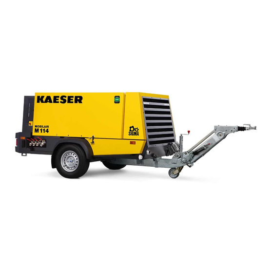
KAESER KOMPRESSOREN SIGMA CONTROL SMART M114 Operator's Manual (364 pages)
Screw Compressor
Brand:
KAESER KOMPRESSOREN
| Category:
Air Compressor
| Size: 16 MB
Table of Contents
Table of Contents
3
Regarding this Document Using this Document
13
Further Documents
13
Copyright
13
Symbols and Labels
13
Warnings
13
Tab. 1 Danger Levels and Their Definitions (Personal Injury)
13
Potential Damage Warnings
14
Other Alerts and Their Symbols
14
Tab. 2 Danger Levels and Their Definition (Damage to Property)
14
Technical Data Nameplate
16
Options - Options Label
16
Tab. 3 Nameplate
16
Compressed Air Treatment Devices
17
Tool Lubricator
17
Compressed Air Distributor
17
Tab. 4 Extract from the Options Label
17
Tab. 5 Compressed Air Treatment Options
17
Tab. 6 Tool Lubricator Option
17
Tab. 7 Compressed Air Distributor Option
17
Low Temperature Equipment
18
Equipment for Fire Hazard Areas
18
Automatic Engine Start/Stop
18
GSM/GPS Modem
18
Chassis
18
Tab. 8 Low Temperature Equipment Options
18
Tab. 9 Optional Equipment for Fire Hazard Areas
18
Tab. 10 Automatic Engine Start/Stop
18
Tab. 11 GSM/GPS Modem
18
Lighting
19
Sealed Floor Pan
19
Anti-Theft Device
19
Tab. 12 Chassis Options
19
Tab. 13 Options, Stationary Frame
19
Tab. 14 Lighting Options
19
Tab. 15 Sealed Floor Pan Option
19
Tab. 16 Anti-Theft Device Option
19
Pedestrian Protection
20
Machine (Without Options)
20
Sound Pressure Level
20
Tightening Torques for Screws
20
Ambient Conditions
20
Additional Specifications
20
Tab. 17 Pedestrian Protection Option
20
Tab. 18 Sound Pressure Level
20
Tab. 19 Tightening Torques for Screws (Property Class 8.8, Coefficient of Friction Μ = 0.12)
20
Tab. 20 Ambient Conditions
20
Chassis
21
Mass
21
Tires
21
Fig. 1 Example for Tire Information on the Side Wall
21
Tab. 21 Mass of the Machine
21
Wheel Nut/Bolt Tightening Torque
22
Towbar Tightening Torque
22
Compressor
22
Working Pressure and FAD
22
Compressed Air Outlet
22
Safety Valves
22
Tab. 22 Tires
22
Tab. 23 Wheel Nut/Bolt Tightening Torque
22
Tab. 24 Towbar Tightening Torque
22
Tab. 25 Working Gauge Pressure and FAD
22
Temperature
23
Cooling Oil Recommendation
23
Tab. 27 Safety Relief Valve Opening Pressure
23
Tab. 28 Required Temperatures Readiness to Switch to LOAD Mode
23
Tab. 29 Airend Discharge Temperature
23
Tab. 30 Cooling Oil Recommendations
23
Cooling Oil Charge
24
Tab. 31 Cooling Oil Recommendation (Food Processing)
24
Engine
25
Engine Specification
25
Oil Recommendation
25
Tab. 32 Cooling Oil Charge
25
Tab. 33 Engine Specification
25
Fuel Recommendation
26
Tab. 34 Engine Oil Recommendation
26
Tab. 35 Initial Engine Oil Quantity
26
Engine Coolant Recommendation
27
Fluid Volumes
27
Batteries
27
Tab. 36 Water Quality Parameters for Cooling Water
27
Tab. 37 Fluid Volumes
27
Tab. 38 Batteries
27
Options
28
Air Treatment Options
28
Tab. 39 Road Breaker Lubricant Recommendation
28
Tab. 40 Fresh Air Filter Conditions
28
Low Temperature Equipment
29
Trickle Charging for Starter Batteries
29
Tab. 41 Interrelation between Compressed Air Treatment and Compressed Air Quality
29
Tab. 42 Environmental Conditions, Low Temperature Equipment
29
Tab. 43 Coolant Pre-Heater
29
Tab. 44 Batteries, Low-Temperature Equipment
29
Tab. 45 Battery Charger Specification
30
Tab. 46 Power Supply Details
30
Safety and Responsibility Basic Instructions
31
Specified Use
31
Incorrect Use
31
User's Responsibilities
31
Observe Statutory and Universally Accepted Regulations
31
Determining Personnel
32
Adherence to Inspection Schedules and Accident Prevention Regulations
32
Taking the Machine for General Inspection
32
Documenting the Mileage of the Machine as Trailer
33
Dangers
33
Safely Dealing with Sources of Danger
33
Tab. 47 General Inspection Intervals
33
Safe Machine Operation
36
Organizational Measures
40
Danger Areas
40
Safety Devices
40
Safety Signs
40
Tab. 48 Danger Areas
40
Fig. 2 Location of Safety Signs
41
Noise Control Requirements
44
Emergencies
44
Correct Fire Fighting
44
Tab. 49 Safety Signs
44
Contact with Operating Fluids/Materials
45
Warranty
45
Noise Emissions Warranty
46
Identifying the Effects of Improper Modifications
46
Environmental Protection
47
Design and Function Bodywork
48
Fig. 3 Overview of Bodywork
48
Machine Structure
49
Machine Function
49
Fig. 4 Right-Hand Door Opened
49
Fig. 5 Left-Hand Door Opened
49
Fig. 35 "Battery Isolating Switch
49
Fig. 6 Machine Overview
50
Operating Modes and Control Mode
51
Machine Operating Modes
51
MODULATING Control
51
Safety Devices
52
Monitoring Functions with Shut-Down
52
Further Safety Devices
52
Fig. 7 Stepless Regulation of FAD(Standstill)
52
Battery Isolating Switch
53
SIGMA CONTROL SMART Control Panel
53
Fig. 8 Battery Isolating Switch
53
Fig. 9 SIGMA CONTROL SMART Operator Panel - Overview
53
Emission After-Treatment
54
Tab. 50 Instrument Panel Keys and Displays
54
Options
55
Fig. 10 Principle of Treatment Devices
55
Air Treatment Options
56
Fig. 11 Compressed Air Options
56
Fig. 12 Tool Lubricator
58
Fig. 13 Principle Tool Lubricator
58
Low Temperature Equipment Options
59
Options for Operating in Fire Hazard Areas
59
Fig. 14 Coolant Pre-Heating
59
Fig. 15 Engine Air Shut-Off Valve
60
Start/Stop/Automatic Options
61
GSM/GPS Modem" Option
61
Transport Options
61
Fig. 16 Access Engine Air Shut-Off Valve
61
Sealed Floor Pan Option
63
Fig. 17 Position of Service Openings in the Sealed Floor Pan
63
Optional Anti-Theft Device
64
Pedestrian Protection Option
64
Fig. 18 Drain Points for Oil and Coolant from Engine and Compressor
64
Installation and Operating Conditions
65
Ensuring Safety
65
Installation Conditions
65
Fig. 19 Minimum Distance from Excavations/Slopes and Walls
65
Machine with Stationary Frame Structure
66
Installation
67
Ensuring Safety
67
Reporting Transport Damage
67
Fitting the Tow Bar
67
Fitting the Height Adjustable Tow Bar
68
Fig. 20 Height Adjustable Tow Bar, Fitted
68
Fig. 21 Fitting the Height Adjustable Tow Bar
68
Fitting a Non-Adjustable Tow Bar
69
Fig. 22 Non-Adjustable Tow Bar Fitted
69
Fig. 23 Fitting the Overrun Braking Mechanism of the Non-Adjustable Tow Bar
70
Adjusting the Chassis
71
Fig. 24 Fitting the Jockey Wheel of the Non-Adjustable Tow Bar
71
Adjusting the Tow Bar Height
72
Changing the Towing Eye/Ball Hitch
72
Fig. 25 Tow Bar Height Adjustment
72
Fig. 26 Changing the Towing Eye (Height-Adjustable Tow-Bar)
73
Fig. 27 Changing the Towing Eye/Ball Hitch (Fixed Height Tow Bar)
74
Fig. 28 Changing the Towing Eye (Fixed Height Tow Bar, USA Chassis Version)
75
Connecting the Battery Trickle Charger
76
Installing a Machine with Stationary Frame Superstructure on a Truck Platform
76
Initial Start-Up Ensuring Safety
78
Before Initial Start-Up (or Recommissioning)
78
Instructions to be Observed before Commissioning or Recommissioning
78
Special Measures for Recommissioning after Storage
79
Checking Installation and Operating Conditions
79
Tab. 51 Measures for Recommissioning the Compressor after a Long Period of Storage
79
Tab. 52 Positioning and Operating Conditions Checklist
79
Low-Temperature Operation (Winter)
80
Starting Assistance
80
Fig. 29 Jumper Cable Connection Diagram
81
Starting up Low-Temperature Equipment
82
Trickle-Charging the Battery
83
Fig. 30 Coolant Pre-Heating
83
Fig. 31 Battery Charger
84
Tab. 53 Standard Battery Charger Readings
84
Operation
85
Ensuring Safety
85
Starting and Stopping
86
Fig. 32 Starting Instruments
86
Follow the Brief Instructions
87
Fig. 33 Instrument Panel Keys and Indicators
87
Fig. 34 Brief Instructions on Starting and Stopping
87
Starting the Machine
88
Setting the Compressed Air Discharge Pressure
89
Fig. 36 Setting the Quick Access for the Compressed Air Discharge Pressure
90
Shutting down the Machine
91
Fig. 37 Setting the Compressed Air Discharge Pressure
91
Shutting down in an Emergency
93
Confirming Alarm and Warning Messages
93
Acknowledging Alarm Messages
93
Acknowledging Warning Messages
94
Operating the Tool Lubricator
94
Fig. 38 Setting the Tool Lubricator
95
Using the Low-Temperature Equipment
96
Shut down the Machine if any Dangerous Situation Arises
96
Fig. 39 Handle for Manually Closing the Engine Air Intake Valve
96
Cleaning the Machine after Operation
97
Fault Recognition and Rectification
98
Basic Instructions
98
Analysing SIGMA CONTROL SMART Messages
98
Alarm Messages on the Controller (Machine Off)
98
Tab. 54 Alarm Messages and Actions Concerning the Engine
99
Tab. 55 Alarm Messages and Actions Concerning the Compressor Unit
100
Tab. 56 Alarm Messages and Actions Concerning the Controller
100
Warning Message on the Controller
101
Tab. 57 General Alarm Messages and Measures
101
Tab. 58 Warning Messages and Measures Relating to the Engine
102
Evaluating Engine Faults and Alarms
103
Tab. 59 Warning Messages and Measures Relating to the Compressor
103
Tab. 60 General Warning Messages and Measures
103
Engine Does Not Reach Full Speed
104
Tab. 61 Fault: Engine Refuses to Start or Comes to a Stop
104
Tab. 62 Alarm: "Engine Does Not Reach Full Speed
104
Analysing Compressor Faults and Alarms
105
Working Pressure too High
105
Working Pressure too Low
105
Tab. 63 Fault: Working Pressure too High
105
Tab. 64 Fault: Working Pressure too Low
105
Pressure Relief Valve Blowing off
106
Machine Overheating
106
Tab. 65 Fault: Pressure Relief Valve Blowing off
106
Tab. 66 Fault: Machine Overheating
106
Too Much Oil Residue in the Compressed Air
107
Oil Flows from the Compressor Air Filter after Shutdown
107
High Moisture Content in the Compressed Air
107
Tab. 67 Alarm: "Too Much Oil Residue in the Compressed Air
107
Tab. 68 Alarm: "Oil Flows from the Compressor Air Filter after Shutdown
107
Tab. 69 Fault: High Moisture Content in the Compressed Air
107
10 Maintenance
108
Ensuring Safety
108
Tab. 70 Advise Others that the Machine Is Being Serviced
108
Noting the Maintenance Messages on the Controller
109
Evaluating the Maintenance Message
109
Tab. 71 Maintenance Messages and Required Actions
109
Maintenance Messages
110
Maintenance Schedules
110
Logging Maintenance Work
110
Maintenance Tasks after Commissioning
110
Regular Maintenance Tasks
111
Tab. 72 Maintenace Tasks on the Machine after Commissioning
111
Tab. 73 Maintenance Tasks on the Chassis after Commissioning
111
Tab. 74 Maintenance Intervals and Regular Maintenance Tasks
112
Tab. 75 Regular Machine Maintenance Tasks
114
Tab. 76 Regular Maintenance Task Options
115
Tab. 77 Chassis Maintenance Intervals and Regular Maintenance Tasks
115
Tab. 78 Regular Chassis Maintenance Tasks
116
Engine Maintenance
117
Water Cooler Maintenance
117
Fig. 40 Checking Coolant Level
118
Tab. 79 KAESER Coolant Mixture Table
119
Fig. 41 Draining the Coolant from the Radiator
120
Engine Air Filter Maintenance
121
Fig. 42 Engine Air Filter Maintenance
122
Fig. 43 Cleaning the Filter Element
122
Fuel System Maintenance
123
Fig. 44 Fuel System Maintenance
124
Fig. 45 Bleeding the Fuel System
124
Fig. 46 Warning Messages: Fuel Filter Water Level
125
Fig. 47 Emptying the Fuel Pre-Filter and Water Trap
126
Fig. 48 Changing the Fuel Pre-Filter Cartridge
127
Fig. 49 Fuel Fine Filter Maintenance
128
Checking the Engine Oil Level
129
Fig. 50 Checking the Engine Oil Level
129
Engine Oil Filling and Topping off
130
Changing the Engine Oil
130
Fig. 51 Draining the Engine Oil
131
Replace the Engine Oil Filter
132
Fig. 52 Change the Oil Filter
132
Engine Belt Maintenance
133
Fig. 53 Belt Guard Attachment
134
Fig. 54 Checking the Drive Belt Seating
134
Fig. 55 Manually Checking the Belt Tension
135
Fig. 56 Changing/Tensioning the Drive Belt
136
Battery Maintenance
138
Fig. 57 Safety Signs - Warning Stickers on the Battery
138
Checking the Fastening of the Fuel Tank
140
Compressor Maintenance
141
Checking the Cooling Oil Level
141
Cooling Oil Filling and Topping off
142
Fig. 58 Check the Cooling Oil Level
142
Changing the Cooling Oil
143
Fig. 59 Draining the Compressor Cooling Oil
144
Replacing the Compressor Oil Filter
145
Fig. 60 Change the Oil Filter
146
Oil Separator Tank Dirt Trap Maintenance
147
Fig. 61 Oil Separator Tank Dirt Trap Maintenance
147
Changing the Oil Separator Cartridge
148
Fig. 62 Changing the Oil Separator Cartridge
149
Compressor Air Filter Maintenance
150
Fig. 63 Compressor Air Filter Maintenance
151
Fig. 64 Cleaning the Filter Element
152
Checking Safety Relief Valves
153
Fit the Flexible Pipe Connection
153
Fig. 65 Fit the Flexible Pipe Connection
153
Tab. 80 Dimensions of the Flexible Pipe Connection
153
Cleaning the Cooler
154
Cleaning the Compressor Cooler and Engine Radiator
154
Cleaning the Compressed Air Aftercooler
155
Fig. 66 Cleaning the Compressor Cooler and Engine Radiator
155
Maintenance of Rubber Sealing Strips
156
Fig. 67 Cleaning the Compressed Air Aftercooler
156
Chassis Maintenance
157
Wheel Checks
157
Towbar Maintenance
157
Fig. 68 Tow Bar Maintenance
158
Fig. 69 Maintaining the Fixed Height Towbar
158
Fig. 70 Ball Coupling ( EC Version)
159
Brake Maintenance
160
Fig. 71 Ball Coupling (USA Version)
160
Fig. 72 Checking the Brake Lining Thickness
161
Fig. 73 Brake System Adjustment
161
Fig. 74 Brake Rod Adjustment
162
Maintenance for Optional Items
163
Tool Lubricator Maintenance
163
Fig. 75 Tool Lubricator Maintenance
164
Cyclone Separator Maintenance
165
Fig. 76 Cleaning the Dirt Trap
165
Combination Filter Maintenance
166
Fig. 77 Filter Combination
167
Fig. 78 Combination Filter Maintenance
167
Fresh Air Filter Maintenance
170
Fig. 79 Fresh Air Filter Maintenance
170
Engine Air Intake Shut-Off Valve Maintenance
173
Fig. 80 Maintain the Engine Air Shut-Off Valve
173
Fig. 81 Checking Manual Operation of the Engine Air Intake Valve
174
Spark Arrestor Maintenance
175
Fig. 82 Cleaning the Spark Arrestor (Floor Pan with Service Openings)
176
Fig. 83 Cleaning the Spark Arrestor (Sealed Floor Pan)
176
Draining Liquid Accumulation Within the Machine
177
Documenting Maintenance and Service Work
179
Tab. 81 Maintenance Log
179
11 Spares, Operating Materials, Service
180
Note the Nameplate
180
Ordering Consumable Parts and Operating Fluids/Materials
180
Tab. 82 Compressor Spare Parts
180
Kaeser Air Service
181
Service Addresses
181
Replacement Parts for Service and Repair
181
Tab. 83 Consumable Engine Parts
181
Tab. 84 Replacement Parts, Combination Filter
181
Tab. 85 Replacement Parts, Fresh-Air Filter
181
12 Decommissioning, Storage and Transport
236
Commissioning
236
Temporary De-Commissioning
236
Tab. 86 "Temporarily Decommissioned" Information Notice
236
Long-Term Decommissioning and Storage
237
Tab. 87 Long-Term Decommissioning and Storage Checklist
237
Transport
238
Safety
238
Towing the Compressor on the Road
238
Tab. 88 Text for the Long-Term Decommissioned and Storage Information Notice
238
Fig. 84 Transport Position
240
Fig. 85 Ball Coupling (ALKO-EU)
241
Fig. 86 Wear Alert, Ball Coupling (ALKO-EU)
242
Tab. 89 Ball Coupling Wear Indicator
242
Fig. 87 Ball Coupling (ALKO-USA)
243
Fig. 88 Release the Parking Brake
243
Fig. 89 Automatic Jockey Wheel in Transport Position
244
Fig. 90 Safety Signs: Secure the Chocks
245
Fig. 91 Breakaway Cable Attachment
246
Fig. 92 Attach Safety Chains
246
Parking the Machine
247
Fig. 93 Warning "Injury Can Occur if the Tow Bar Is Allowed to Fall
247
Fig. 94 Tow Bar with Automatic Jockey Wheel
248
Fig. 95 Actuating the Parking Brake
248
Fig. 96 Safety Signs: Secure with Chocks
249
Transport with a Crane
250
Transport with a Forklift Truck
251
Transporting the Machine as Load
251
Fig. 97 Transporting Using a Forklift Truck
251
Fig. 98 Guys to Secure the Freight
252
Storage
253
Disposal
253
13 Annex
254
Marking
254
Pipeline and Instrument Flow Diagram (P+I Diagram)
254
Fig. 99 Marking
254
Dimensional Drawings
259
Dimensional Drawing - Chassis
259
Dimensional Drawing, Chassis Options
261
Dimensional Drawing, Chassis Options
263
Dimensional Drawing, Chassis Options
265
Dimensional Drawing, Stationary Version
267
Dimensional Drawing, Stationary Version
269
Wiring Diagrams
271
Electrical Diagram
271
Lighting and Signaling System Connection
289
Lighting and Signaling System Connection
297
Battery Charger Electrical Diagram
302
Fuel Circulation Diagram
312
Assembly Diagrams - Chassis
315
Assembly Diagrams - Chassis EU Version
315
Assembly Diagrams - Chassis GB/US Version
317
Assembly Diagram Brake Rod
320
Operating Instructions for Compressed Air Filter (Combination Filter)
322
Operating Instructions for Compressed Air Filter (Fresh Air Filter)
350
Advertisement
Advertisement
Related Products
KAESER KOMPRESSOREN M170
KAESER KOMPRESSOREN MOBILAIR M58utility
KAESER KOMPRESSOREN MOBILAIR M27
KAESER KOMPRESSOREN SIGMA CONTROL SMART MOBILAIR M82
KAESER KOMPRESSOREN MOBILAIR M55 PE
KAESER KOMPRESSOREN M250
KAESER KOMPRESSOREN MOBILAIR M250E
KAESER KOMPRESSOREN MOBILAIR M255E
KAESER KOMPRESSOREN M 121
KAESER KOMPRESSOREN MOBILAIR M125 SIGMA CONTROL MOBIL pV
KAESER KOMPRESSOREN Categories
Air Compressor
Controller
Blower
Dryer
Dehumidifier
More KAESER KOMPRESSOREN Manuals
Login
Sign In
OR
Sign in with Facebook
Sign in with Google
Upload manual
Upload from disk
Upload from URL