KAESER KOMPRESSOREN SIGMA CONTROL 2 User Manual
Screw dry 3.3.x
Hide thumbs
Also See for SIGMA CONTROL 2:
- User manual (260 pages) ,
- Service manual (238 pages) ,
- User manual (184 pages)

Related Manuals for KAESER KOMPRESSOREN SIGMA CONTROL 2


Summary of Contents for KAESER KOMPRESSOREN SIGMA CONTROL 2
- Page 1 User Manual Controller SIGMA CONTROL 2 SCREW DRY ≥ 3.3.X No.: 9_9451 04 E Manufacturer: KAESER KOMPRESSOREN SE 96410 Coburg • PO Box 2143 • GERMANY • Tel. +49-(0)9561-6400 • Fax +49-(0)9561-640130 www.kaeser.com...
- Page 2 /KKW/SSC 2.11 en IBA-SIGMA CONTROL DRY /KKW/SSC 2.11 20200703 102433...
-
Page 3: Table Of Contents
Variable speed drive with frequency converter (SFC) ........Installation and Operating Conditions Maintaining ambient conditions ..................Installation conditions ....................... Installation Reporting Transport Damage ................... Machine identification ....................... User Manual Controller No.: 9_9451 04 E SIGMA CONTROL 2 SCREW DRY ≥ 3.3.X... - Page 4 Setting the nominal pressure change via timer ........... 8.10 Setting the machine for master control operation ............8.10.1 Overview of the different master operating modes ..........100 User Manual Controller SIGMA CONTROL 2 SCREW DRY ≥ 3.3.X No.: 9_9451 04 E...
- Page 5 9.14.2 Setting "f" parameters ..................172 9.14.3 Setting the operating mode ................. 173 9.15 Save data ......................... 174 Fault Recognition and Rectification 10.1 Basic instructions ......................177 User Manual Controller No.: 9_9451 04 E SIGMA CONTROL 2 SCREW DRY ≥ 3.3.X...
- Page 6 Decommissioning, Storage and Transport 13.1 De-commissioning ......................212 13.2 Packing ..........................13.3 Storage ..........................212 13.4 Transporting ........................212 13.5 Battery removal and disposal ................... 212 User Manual Controller SIGMA CONTROL 2 SCREW DRY ≥ 3.3.X No.: 9_9451 04 E...
- Page 7 Insert the communication module....................Fig. 33 Front plate communication module Profibus ................108 Fig. 34 Direct connection of two SIGMA CONTROL 2 ................113 Fig. 35 LOAD remote contact ......................... 118 Fig. 36 Switching the compressed air station on and off ................ 143 Fig.
- Page 8 List of Illustrations User Manual Controller SIGMA CONTROL 2 SCREW DRY ≥ 3.3.X No.: 9_9451 04 E...
- Page 9 Pressure conditions for IDLE ...................... Setpoint pressure ..................... Tab. 52 Setting limits for Tab. 53 Pressure condition for LOAD ...................... Tab. 54 Pressure conditions for IDLE ...................... User Manual Controller No.: 9_9451 04 E SIGMA CONTROL 2 SCREW DRY ≥ 3.3.X...
- Page 10 Alarm messages and remedies ....................177 Tab. 87 Warning messages and remedies ....................191 Tab. 88 Operating messages ........................203 Tab. 89 System messages and remedies ....................208 User Manual Controller viii SIGMA CONTROL 2 SCREW DRY ≥ 3.3.X No.: 9_9451 04 E...
-
Page 11: Sigma Control 2 Quick Installation Guide
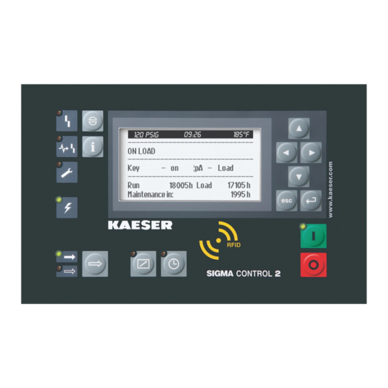
SIGMA CONTROL 2 Quick installation guide Operating elements 1 SIGMA CONTROL 2 Quick installation guide Operating elements Fig. 1 Operating elements Item Designation Function «Up» Scrolls up the menu options. Increases a parameter value. «Left» Jumps to the left. Moves the cursor position to the left. -
Page 12: Display Elements
Main menu – Overview Press «Up» / «Down» / «Enter» to open the main menu. Menu No. Menu name Function Status Displays messages, statistics and status information User Manual Controller SIGMA CONTROL 2 SCREW DRY ≥ 3.3.X No.: 9_9451 04 E... -
Page 13: Functions - Overview
<Compressor clock – Key clock – ☑> Activating the 8.5.1.3 «time control» Activating – Activate the «Time control» key – Press «Time control» key 8.5.1.4 «time control» User Manual Controller No.: 9_9451 04 E SIGMA CONTROL 2 SCREW DRY ≥ 3.3.X... -
Page 14: Tab. 4 Functions - Overview
Y. Tab. 4 Functions – Overview Settings can be made after log-in with the RFID Equipment Card and access level 2. User Manual Controller SIGMA CONTROL 2 SCREW DRY ≥ 3.3.X No.: 9_9451 04 E... -
Page 15: Regarding This Document Using This Document
The licenses can be also found under these addresses: http://www.gnu.org/licenses http://code.google.com/p/curve25519-donna/ Within three years from receipt of SIGMA CONTROL 2, you may obtain the complete source code of the copyright-protected software packages by sending a corresponding order to the following ad‐ dress:... -
Page 16: Certification
➤ Please note the symbols and labels used in this document. 2.5.1 Warnings Warnings indicate danger potentially resulting in personal injury, if the measures specified are not taken. User Manual Controller SIGMA CONTROL 2 SCREW DRY ≥ 3.3.X No.: 9_9451 04 E... -
Page 17: Potential Damage Warnings
Potential effects when ignoring the warning are indicated here. ➤ The protective measures against the damages are shown here. ➤ Carefully read and fully comply with warnings against damages. User Manual Controller No.: 9_9451 04 E SIGMA CONTROL 2 SCREW DRY ≥ 3.3.X... -
Page 18: Other Alert Notes And Their Symbols
➤ ... as is a solution. This symbol identifies important information or measures regarding the protection of the envi‐ ronment. Further information Further subjects are introduced here. User Manual Controller SIGMA CONTROL 2 SCREW DRY ≥ 3.3.X No.: 9_9451 04 E... -
Page 19: Technical Specifications 3.1 Controller Sigma Control 2
255 x 128 Width [mm] Height [mm] Maximum number of lines/characters 8/30 Colours Black/white with grey scale Lighting LED backlit px ≙ pixel Tab. 9 Display data User Manual Controller No.: 9_9451 04 E SIGMA CONTROL 2 SCREW DRY ≥ 3.3.X... -
Page 20: Fig. 3 Mcs Interfaces
The positions of the interfaces X1–X6 are marked on the rear of the controller. Tab. 10 MCS interfaces Identification with RFID Equipment Card Characteristic Value Hardware on the SIGMA CONTROL 2 controller RFID reader Hardware (external) RFID Equipment Card Recognition distance [m] Max. 0.05 Frequency [MHz] 13.56... -
Page 21: Input/Output Modules
Digital output relay (DOR), 250 VAC, 8 A – – Digital output transistor (DOT), 24 VDC, 0.5 A – Analogue output current (AOI), 0–20 mA – – Tab. 13 SC2IOM-2 User Manual Controller No.: 9_9451 04 E SIGMA CONTROL 2 SCREW DRY ≥ 3.3.X... -
Page 22: Tab. 14 Sc2Iom-3
Power is provided by the power supply unit within the machine. Characteristic Value Rated voltage (stabilised) [V DC] Current consump‐ tion SIGMA CONTROL 2 with IOM 1 [A] Current consumption IOM 2 [A] Current consumption IOM 3 [A] IOM ≙ Input/Output module Tab. 15 Power supply specifications 3.1.2.2... -
Page 23: Sensors
Output signal [mA] 0/4–20 Connection Two-core Tab. 19 Pressure transducer Resistance thermometer Characteristic Value Sensing resistance (to DIN IEC 751) PT100 Connection Two-core Tab. 20 Resistance thermometer User Manual Controller No.: 9_9451 04 E SIGMA CONTROL 2 SCREW DRY ≥ 3.3.X... -
Page 24: Safety And Responsibility Basic Instructions
The safety regulations of the machine in which SIGMA CONTROL 2 is installed apply. Specified use SIGMA CONTROL 2 is solely intended for the control of machines in which SIGMA CONTROL 2 is factory-installed. Any other use is considered incorrect. The manufacturer is not liable for any dam‐... -
Page 25: Design And Function
Manual loading of updates with an SC card, reading or recording process data ■ Input-Output-Module (IOM): For SIGMA CONTROL 2 (Prepared for connection to control centre): modules with digital and analogue inputs and outputs with autonomous power supply. Fig. 4... -
Page 26: Operating Panel
Moves the cursor position to the left. «Right» Jumps to the right. Moves the cursor position to the right. «Down» Scrolls down the menu options. Reduces a parameter value. not for SXC User Manual Controller SIGMA CONTROL 2 SCREW DRY ≥ 3.3.X No.: 9_9451 04 E... -
Page 27: Display Elements
Continuous green light when the machine is in remote control. IDLE Continuous green light when the machine is running in IDLE. Flash‐ es when the «LOAD/IDLE» toggle key is pressed. not for SXC User Manual Controller No.: 9_9451 04 E SIGMA CONTROL 2 SCREW DRY ≥ 3.3.X... -
Page 28: Rfid Reader
Placing a suitable transponder in front of the RFID reader of the controller will automatically acti‐ vate the communication between transponder and SIGMA CONTROL 2. A suitable transponder is the RFID Equipment Card. Two of them have been provided with the ma‐... -
Page 29: Display
T2 SIGMA CONTROL 2 Working gauge pressure – Time PISTON Tab. 24 Data in the header depending on the machine type User Manual Controller No.: 9_9451 04 E SIGMA CONTROL 2 SCREW DRY ≥ 3.3.X... -
Page 30: Main Menu
Press «Enter» to open a menu in the active line. This opens the selected menu. You change parameters in Setting mode. User Manual Controller SIGMA CONTROL 2 SCREW DRY ≥ 3.3.X No.: 9_9451 04 E... -
Page 31: Setting Parameters
5.3.4 Activating keys with check boxes Certain keys of the SIGMA CONTROL 2 are locked by default. Activate the corresponding check boxes in the active line of the display to unlock these keys. First, press «Enter» to switch into setting mode. The check box will flash. -
Page 32: Kaeser Connect
For this purpose, you must generate a password once (see Chapter 8.2.5). KAESER CONNECT does not require additional software to do so. The display language of KAESER CONNECT can be set independently to the language used with SIGMA CONTROL 2. Fig. 8... -
Page 33: Menu Overview
■ Date display format ■ Time display format Backup Saving data via KAESER CONNECT from SIGMA CONTROL 2 to a PC not for SXC Tab. 27 KAESER CONNECT functions Further information For opening KAESER CONNECT, login and other procedures, please see chapter 8.3. -
Page 34: Menu Structure
■ Enter customer-specific settings The menus shown require access level 2. Depending on the SIGMA CONTROL 2 software version, machine type and available op‐ tions, only the menus that are available for this particular machine will be displayed. Main menu... - Page 35 SIGMA CONTROL 2 First IOM Second IOM Third IOM Fourth IOM ■ Curves ─ p100(t) T100(t) ─ T4(t) T100(t) ─ pN(t) n710(t) ─ T10(t) T14(t) ─ p14(t) T14(t) User Manual Controller No.: 9_9451 04 E SIGMA CONTROL 2 SCREW DRY ≥ 3.3.X...
- Page 36 RD fan motor Bearing lube Bearing change RD drum motor Oil change Electrical equipment Annual maintenance Configuration menu, please 5 Configuration For details of the see table 30. User Manual Controller SIGMA CONTROL 2 SCREW DRY ≥ 3.3.X No.: 9_9451 04 E...
- Page 37 ■ Test T85⇞ always RD, compressed air outlet, air temperature ■ Test T86⇞ always Heat exchanger downstream of RD: Air tem‐ perature at compressed air outlet User Manual Controller No.: 9_9451 04 E SIGMA CONTROL 2 SCREW DRY ≥ 3.3.X...
-
Page 38: Tab. 28 Menu Structure Of Main Menu
Actual pressure Frequency converter Setpnt press. Actual pressure 1.4 Current operating mode Compressor on Load control Control mode Idle period Acknowledgement Power switching with frequency converter User Manual Controller SIGMA CONTROL 2 SCREW DRY ≥ 3.3.X No.: 9_9451 04 E... -
Page 39: Tab. 29 Status Menu
Pressure unit Temperature unit Display lighting ■ Compressor start ─ Compressor ON ─ Compressor OFF ─ Motor start ■ Acknowledgement Remote mode Key remote RC ack User Manual Controller No.: 9_9451 04 E SIGMA CONTROL 2 SCREW DRY ≥ 3.3.X... - Page 40 Local mode ■ DUAL ─ Idle period ■ QUADRO ─ Min. run period ─ Unloaded period Idle Period min Ambient pressure Oper. mode p3a/Fixed value pAmb User Manual Controller SIGMA CONTROL 2 SCREW DRY ≥ 3.3.X No.: 9_9451 04 E...
-
Page 41: Tab. 30 Configuration Menu
External message 3 ■ External message 4 ■ External message 5 ■ External message 6 5.3.1.3 Analogue values ■ AnMod ■ ■ I/O periphery menu Tab. 31 User Manual Controller No.: 9_9451 04 E SIGMA CONTROL 2 SCREW DRY ≥ 3.3.X... - Page 42 Compressor number Language Repeat cut-off time SSL activ Sender address: Sender name: Contact telephone: Receiver address: SMTP Server: User name: Password: Port Resend after: MAC: MAC address User Manual Controller SIGMA CONTROL 2 SCREW DRY ≥ 3.3.X No.: 9_9451 04 E...
-
Page 43: Tab. 32 Communication Menu
─ Main fan ─ Fan T100 ■ Refrigeration dryer ─ Oper. mode ─ Analogue values ─ Messages ■ Rotation dryer ─ Messages Components menu Tab. 33 User Manual Controller No.: 9_9451 04 E SIGMA CONTROL 2 SCREW DRY ≥ 3.3.X... -
Page 44: Additional Information
Design and Function Additional information Additional information Depending on the used compressor model, SIGMA CONTROL 2 displays additional information in existing menus, such as the following: Menu Information 1.3 Current pressure Switching points and switching differentials control 2 Performance data... -
Page 45: Control Modes
The objective of this regulation is to attain the best possible energy efficiency and, at the same time, to limit the number of switching actions (cutting in and out of the compressor motor) as low as possible to prevent damage to the motor. The controller SIGMA CONTROL 2 can operate in the following modes: ■ DUAL ■... -
Page 46: Variable Speed Drive With Frequency Converter (Sfc)
If the compressed air demand rises, the motor speed increases and consequently the volume of air delivered. If air consumption drops, SIGMA CONTROL 2 reduces the motor speed and, therefore, the volume of air delivered. The network pressure remains constant – within the control range of the converter – regardless of fluctuating air demand. -
Page 47: Installation And Operating Conditions
Direct sunlight (UV radiation) can destroy the display screen. ➤ Do not allow the display screen to be subjected to direct sunlight. ➤ See the machine's operating manual for required conditions. User Manual Controller No.: 9_9451 04 E SIGMA CONTROL 2 SCREW DRY ≥ 3.3.X... -
Page 48: Installation
Time control: Risk of injury caused by unexpected starting! ➤ Make sure the power supply disconnecting device is switched off before commencing any work on the machine. Tab. 38 Machine identification User Manual Controller SIGMA CONTROL 2 SCREW DRY ≥ 3.3.X No.: 9_9451 04 E... -
Page 49: Initial Start-Up Outline
8 Initial Start-up Outline SIGMA CONTROL 2 was designed and developed for a number of applications. The settings that can be made are correspondingly varied. It is possible that only a few of these settings are needed for the initial start-up. This depends on the application involved. -
Page 50: Selecting Menu Options
All menu options can be selected with the «Down», «Up» and «Enter» keys. Example: Open the < Configuration – General > menu. 1. Switch on the machine and wait for SIGMA CONTROL 2 to start. The operating mode is displayed. - Page 51 General menu such as System 9. Use the «Up» or «Down» key to select a menu item in the information . 10. Press «Escape» repeatedly to leave this menu. User Manual Controller No.: 9_9451 04 E SIGMA CONTROL 2 SCREW DRY ≥ 3.3.X...
-
Page 52: Setting The Language
Initial Start-up Setting the controller 8.2.2 Setting the language You can choose and set the user interface language for SIGMA CONTROL 2: Arabic Estonian Italian Norwegian Spanish Bulgarian Finnish Japanese Polish Spanish (South America) Chinese French Korean Portuguese Czech Danish... -
Page 53: Noting The User Name
SIGMA CONTROL 2 (see chapter 8.2.5). 8.2.4 User log-in with RFID Equipment Card The RFID Equipment Card enables an easy and quick log-in at SIGMA CONTROL 2. It authorises you to access advanced functions of the controller. Advanced access rights allow you to: ■... -
Page 54: Generating A Password
SIGMA CONTROL 2. Note this generated password as well, and store it a suitable location. If your RFID Equipment Card is damaged or lost, the card won't be nec‐ essary to manually log on to SIGMA CONTROL 2 when you have these two pieces of information. Precondition Any menu is displayed Fig. -
Page 55: Manual User Log-In
2. Use «Up» or «Down» to select the 3. Press «Enter». The setting mode is active. A column with alphanumeric characters is displayed. The selected character flashes. User Manual Controller No.: 9_9451 04 E SIGMA CONTROL 2 SCREW DRY ≥ 3.3.X... -
Page 56: Create The Master Rfid Equipment Card
11. Use «Up» or «Down» to select the 12. Press «Enter». Current access level: 2 is displayed. Result You are now logged on to SIGMA CONTROL 2 with access level 2, having manually input your user name and the password. 8.2.7 Create the master RFID Equipment Card If you are running several KAESER machines with the SIGMA CONTROL 2 control it may make sense to create a master RFID Equipment Card with which you can log onto all machines. -
Page 57: Checking/Setting Time And Date
See chapter 8.2.16. <Configuration – Machine – General> menu. 1. Open the 5.1.1 Date/time line. 2. Use «Up» or «Down» to select the User Manual Controller No.: 9_9451 04 E SIGMA CONTROL 2 SCREW DRY ≥ 3.3.X... - Page 58 00.00.00 flashes. The display for days 5. Use «Up» or «Down» to set the day. 6. Press the «Right» arrow. 00.00.00 flashes. The display for months User Manual Controller SIGMA CONTROL 2 SCREW DRY ≥ 3.3.X No.: 9_9451 04 E...
-
Page 59: Set The Time Zone
11. Press «Escape» repeatedly to leave this menu. 8.2.9 Set the time zone Set the time zone for the SIGMA CONTROL 2 to ensure the timely automatic conversion from win‐ ter time (standard time) to daylight savings time, for example. Precondition Access level 2 is activated. -
Page 60: Tab. 41 Possible Settings For The Time Format
Date format MM/DD/YY Time format Time format hh:mm:ssAM/PM Unit of pressure Pressure unit Unit of temperature Temperature unit °C ------------------------------ 3. Press «Enter». hh:mm:ssAM/PM indication flashes. User Manual Controller SIGMA CONTROL 2 SCREW DRY ≥ 3.3.X No.: 9_9451 04 E... -
Page 61: Tab. 42 Possible Settings For The Pressure Unit
Set the temperature unit for display: Format Example °C 46°C 319K °F 114°F Tab. 43 Possible settings for the temperature unit Precondition Access level 2 is activated. User Manual Controller No.: 9_9451 04 E SIGMA CONTROL 2 SCREW DRY ≥ 3.3.X... -
Page 62: Setting The Display Illumination
Pressure unit Unit of temperature Temperature unit °C ------------------------------ Display lighting Active line Mode: auto¦ Timeout: 1min 4. Press «Enter». The display for the set mode flashes. User Manual Controller SIGMA CONTROL 2 SCREW DRY ≥ 3.3.X No.: 9_9451 04 E... -
Page 63: Setting The Contrast And The Brightness
Contrast and brightness are set. 8.2.13 Activating the remote control The «remote control» key on the operating panel of the SIGMA CONTROL 2 can be activated or deactivated. Various menus offer check boxes for this setting. Precondition Access level 2 is activated. -
Page 64: Ip Configuration
8.2.14 IP configuration For the SIGMA CONTROL 2 to be connected to the network, you must set the IP configuration (for KAESER CONNECT for example). If you use SIGMA CONTROL 2 as the master control of two machines, you set other network IP configuration menu (see chapter 8.10.4). -
Page 65: Setting The E-Mail Function
The network is restarted. The set network parameters are active. 8.2.15 Setting the e-mail function SIGMA CONTROL 2 is able to send messages per e-mail. For this purpose, a network connection with an SMTP server is required. User Manual Controller No.: 9_9451 04 E... - Page 66 The e-mail function is deactivated. 6. Set the e-mail parameters as described above: If SIGMA CONTROL 2 is connected via SIGMA NETWORK to SAM 4.0 and emails are to be SMTP forwarded via SAM 4.0, then enter the IP address of interface X6 of SAM 4.0 in the Server: field.
-
Page 67: Setting The Time Server
8.2.16 Setting the time server If SIGMA CONTROL 2 is connected to the network, you can set the access to an SNTP server available in the Internet or a local Intranet. SIGMA CONTROL 2 then automatically imports the date and time settings and ensures continuous synchronisation of the internal clock with the exter‐... -
Page 68: Kaeser Connect Benefits
12. Press «Escape» repeatedly to leave this menu. Result Access to the selected time server is active. The internal clock of SIGMA CONTROL 2 is permanently synchronised. KAESER CONNECT benefits Using an Internet-capable device with web browser, you can use KAESER CONNECT to remotely display these SIGMA CONTROL 2 menus: ■... -
Page 69: Open Kaeser Connect
The user name (see chapter 8.2.3) and password (see chapter 8.2.5) are known. The controller's IP address is known, see chapters 8.2.14 and 8.10.4. 1. Use an Ethernet cable to connect SIGMA CONTROL 2 to the Internet-capable device or net‐ work. -
Page 70: System Status Menu
7. Click to set the selected language Result KAESER CONNECT is displayed in the set language. 8.3.2 System status menu Precondition KAESER CONNECT for SIGMA CONTROL 2 is displayed. User Manual Controller SIGMA CONTROL 2 SCREW DRY ≥ 3.3.X No.: 9_9451 04 E... -
Page 71: Fig. 16 System Status Menu
Initial Start-up KAESER CONNECT benefits System status menu Fig. 16 System status menu element. 1. Click the System status menu is displayed Fig. 17 Main menu User Manual Controller No.: 9_9451 04 E SIGMA CONTROL 2 SCREW DRY ≥ 3.3.X... -
Page 72: Graphs Menu
Initial Start-up KAESER CONNECT benefits 2. Click in the SIGMA CONTROL 2 display. The Main menu is displayed. 3. Click the numbered lines. The system displays the corresponding sub-menus. 4. Press ESC repeatedly to leave this menu. 8.3.3 Graphs menu... -
Page 73: Fig. 19 Control Keys
An SD card with sufficient free memory is inserted in the X5 SD card slot The SD card was inserted for the entire operating time of the machine. The SIGMA CONTROL 2 data recorder function is activated. Start: . 1. Enter the date and time for the start time in the required time period in End: . -
Page 74: Messages Menu
■ Compressor messages ■ System messages ■ Diagnostic messages Precondition KAESER CONNECT for SIGMA CONTROL 2 is displayed. Messages (illustration similar) Fig. 20 Messages menu element. 1. Click the Messages menu is displayed 2. Click the required message type. 3. Check messages. -
Page 75: User Management Menu
User name: 6 to 16 characters, the second character must not be a number ■ Password: 6 to 16 characters Precondition The generated password is available. KAESER CONNECT for SIGMA CONTROL 2 is displayed. User Manual Controller No.: 9_9451 04 E SIGMA CONTROL 2 SCREW DRY ≥ 3.3.X... -
Page 76: Fig. 22 User Management Menu
User name: field. 3. Enter your user name in the Password: field. 4. Enter your password in the 5. Click OK. User management menu is displayed User Manual Controller SIGMA CONTROL 2 SCREW DRY ≥ 3.3.X No.: 9_9451 04 E... -
Page 77: Fig. 24 User Management Menu
1. Click the required user account in the list. Password: field. 2. Enter a new password in the Repeat password: field. 3. Re-enter the same new password in the 4. Click Update user. User Manual Controller No.: 9_9451 04 E SIGMA CONTROL 2 SCREW DRY ≥ 3.3.X... -
Page 78: Settings Menu
Settings menu Fig. 25 For example, you want to convert your units to US values: Precondition KAESER CONNECT for SIGMA CONTROL 2 is displayed. 1. Click the Settings menu element. 2. Click the arrow key for the unit of pressure. -
Page 79: Save Data Menu
Initial Start-up KAESER CONNECT benefits 8.3.8 Save data menu Backup menu allows you to download data from SIGMA CONTROL 2 to the Internet-capable device. The following backup types are available: ■ Backup all ■ Log files ■ Settings ■ User information Precondition KAESER CONNECT for SIGMA CONTROL 2 is displayed. -
Page 80: Kaeser Connect Exit
The downloaded data can be sent to KAESER SERVICE for evaluation and service support. 8.3.10 KAESER CONNECT exit In order to close KAESER CONNECTfor SIGMA CONTROL 2, click Logout in the header. ➤ Click Logout. Result The system displays a message confirming the successful logout. -
Page 81: Pressure Parameters Of The Machine
SP: Switching point for network pressure low ■ Option: Configure the output signal, Warning message displayed or an additional output signal is sent, e.g., to a control centre User Manual Controller No.: 9_9451 04 E SIGMA CONTROL 2 SCREW DRY ≥ 3.3.X... -
Page 82: Displaying Pressure Parameters
5.0bar ¦ SD 0.50bar ¦ ta 600s DOR1.03 ☐ ------------------------------ Active line Cut-in pressure min 5.0bar 2. Select further parameters with the «Up» and «Down» keys. User Manual Controller SIGMA CONTROL 2 SCREW DRY ≥ 3.3.X No.: 9_9451 04 E... -
Page 83: Setting Pressure Parameters
7. If necessary, adjust the value for the 8. Press «Escape» repeatedly to leave this menu. pA and pB are set. Result The parameters for the network nominal pressure User Manual Controller No.: 9_9451 04 E SIGMA CONTROL 2 SCREW DRY ≥ 3.3.X... -
Page 84: Tab. 52 Setting Limits For Setpoint Pressure
7. If necessary, adjust the value for the 8. Press «Escape» repeatedly to leave this menu. pA and pB are set. Result The parameters for the network nominal pressure User Manual Controller SIGMA CONTROL 2 SCREW DRY ≥ 3.3.X No.: 9_9451 04 E... - Page 85 The pressure increase is added to the set-point pressure. In this way, the set-point pressure can be changed without you having to adjust the parameter again. Precondition Access level 2 is activated. User Manual Controller No.: 9_9451 04 E SIGMA CONTROL 2 SCREW DRY ≥ 3.3.X...
-
Page 86: Fig. 28 Pressure Rise In Frequency-Controlled Machines
6. Press «Escape» repeatedly to leave this menu. 8.4.2.5 Setting "System pressure low" parameters System pressure low , SIGMA CONTROL 2 displays When the network pressure drops to the value a warning message for insufficient network pressure. Be generous when setting the time interval ta for the display of the warning message. -
Page 87: Tab. 56 Example: Activated Output
The setting mode is active. ta . 9. Use the«Up» or «Down» key to set the required value for the time interval 10. Press «Enter». The setting is applied. User Manual Controller No.: 9_9451 04 E SIGMA CONTROL 2 SCREW DRY ≥ 3.3.X... -
Page 88: Machine Start And Machine Stop
Tab. 57 Settings for machine start and machine stop 8.5.1 Automatic start/stop in timer mode Overview Compressor clock menu ■ Open the ■ Set clock program User Manual Controller SIGMA CONTROL 2 SCREW DRY ≥ 3.3.X No.: 9_9451 04 E... -
Page 89: Tab. 58 User-Defined Clock Programme Machine On/Off
In addition to individual weekdays, the controller has the following cycles: ■ Mon-Thu ■ Mon-Fri ■ Mon-Sat ■ Mon-Sun ■ Sat-Thu You can also program an OFF time (plant vacation shut-down) (see Section 8.5.2). User Manual Controller No.: 9_9451 04 E SIGMA CONTROL 2 SCREW DRY ≥ 3.3.X... -
Page 90: Tab. 59 Example Of A Machine On/Off Clock Program
8. Use «Up» or «Down» to set the hours. 9. Press the «Right» arrow. 00 flashes. 10. The display for minutes, 00: 11. Use «Up» or «Down» to set the minutes. User Manual Controller SIGMA CONTROL 2 SCREW DRY ≥ 3.3.X No.: 9_9451 04 E... - Page 91 The check box is activated. 4. Press «Enter». The setting is applied. 5. Press «Escape» repeatedly to leave this menu. Result The «Time control» key is activated. User Manual Controller No.: 9_9451 04 E SIGMA CONTROL 2 SCREW DRY ≥ 3.3.X...
-
Page 92: Setting The Company Shut-Down
Activating time control Precondition The «Time control» key is activated; see chapter 8.5.1.3. ➤ Press the «Time control» key on the SIGMA CONTROL 2 operating panel to activate the time control. Result Time control LED on the operating panel of the SIGMA CONTROL 2 signalises with green continuous light that the machine is operated with activated time control. -
Page 93: Controlling Machine From A Remote Location
If necessary, activate the «Time control» key and configure the time program (see chap‐ ter 8.5.1.2). RC . ■ If required, assign a different input for the remote contact ■ Press the «Remote control» key. User Manual Controller No.: 9_9451 04 E SIGMA CONTROL 2 SCREW DRY ≥ 3.3.X... - Page 94 ☐ Key clock ☐ Remote mode Key+RC . Result The machine start is set to 8.5.3.2 Assigning another input Inputs already assigned cannot be further assigned. User Manual Controller SIGMA CONTROL 2 SCREW DRY ≥ 3.3.X No.: 9_9451 04 E...
-
Page 95: Control Modes
Activating the remote control ➤ Activate remote control see chapter 8.2.13. Result SIGMA CONTROL 2 remote control is activated. Control modes The controller is provided with various control modes that can bring about varying capacity utilisa‐ tion depending on machine application. Chapter 5.8 provides a comprehensive description of all control modes. -
Page 96: Setting The Dual Control Mode
The shorter the period, the more often the machine will switch from IDLE to READY. SIGMA CONTROL 2 will take into account the maximum motor switching capacity. Depending on the machine type, the compressor motor may not fall below a minimum idling or standstill time. -
Page 97: Setting The Quadro Control Mode
Min. run period line. 2. Use the «Up» or «Down» keys to select the 3. Press the «DOWN» key. 4. Press «Enter». The seconds display flashes. User Manual Controller No.: 9_9451 04 E SIGMA CONTROL 2 SCREW DRY ≥ 3.3.X... -
Page 98: Refrigeration Dryer
1 0 0 7 . 2 b a r ¦ # Menu 10.4.4 Refrigeration dryer Active line Oper. mode Continuous ------------------------------ ▶1 Analogue values ▶2 Messages User Manual Controller SIGMA CONTROL 2 SCREW DRY ≥ 3.3.X No.: 9_9451 04 E... -
Page 99: Setting And Activating Messages
10.4.4.2.2.2 T46 On load Active line ⇞ T46 > 90 °C ☐ ¦ ta1 ↑ T46 > 73 °C ¦ ta ------------------------------ ↑ T46 DOR Logic + User Manual Controller No.: 9_9451 04 E SIGMA CONTROL 2 SCREW DRY ≥ 3.3.X... -
Page 100: Rotation Dryer
The operator must decide whether the machine should continue to operate. SIGMA CONTROL 2 shuts the machine down when the pressure dew point drops further below the fault value. You can activate/deactivate a fault message for this fault. - Page 101 The fault message can be activated. ⇞ M85 > −5°C ☐ ¦ ta 600s The system generates a warning message. ↑ M85 > −10°C ¦ ta −2°C ¦ User Manual Controller No.: 9_9451 04 E SIGMA CONTROL 2 SCREW DRY ≥ 3.3.X...
-
Page 102: Setting Additional Parameters In The Pressure Dew Point Menu
−2°C ¦ 11. Press «Enter». The setting is applied. 0605 M85 > %t ¦ load fault message. In the event of a fault, SIGMA CONTROL 2 generates the 12. Press «Escape» repeatedly to leave this menu. Pressure dew point menu 8.8.2 Setting additional parameters in the The parameter for the pressure dew point >... -
Page 103: Setting The Parameter For An Additional Fan
Header p 1 0 0 7 . 2 b a r ¦ # Menu 10.4.3.3.2 Automatic Active line Run on 144s ------------------------------ Lock T100 < 10°C User Manual Controller No.: 9_9451 04 E SIGMA CONTROL 2 SCREW DRY ≥ 3.3.X... -
Page 104: Setting The Machine For Local Mode
Entering the weekday for the first switching point ■ Enter the time of the first switching point. ■ Set the nominal pressure for the first switching point pA or pB User Manual Controller SIGMA CONTROL 2 SCREW DRY ≥ 3.3.X No.: 9_9451 04 E... - Page 105 06:00PM pB on 03:00PM pB on Tab. 62 Example: Switching points, nominal pressure change Deleting an existing timing program Delete an existing timing program as follows: User Manual Controller No.: 9_9451 04 E SIGMA CONTROL 2 SCREW DRY ≥ 3.3.X...
- Page 106 7 . 2 b a r ¦ # Menu 5.2.2.1 pA/pB Clock Reset : ☐ ------------------------------ active line, first switching point n.a. 12:00AM n.a. 12:00AM n.a. 12:00AM n.a. 12:00AM User Manual Controller SIGMA CONTROL 2 SCREW DRY ≥ 3.3.X No.: 9_9451 04 E...
-
Page 107: Setting The Nominal Pressure Change Via Timer
■ Set timer period pA or pB ■ Set starting point for pA/pB Cycle : see chapter 8.9.3.3. ■ Select the operating mode User Manual Controller No.: 9_9451 04 E SIGMA CONTROL 2 SCREW DRY ≥ 3.3.X... - Page 108 8.9.3.2 Set starting time for pA or pB 1. Use the «Up» or «Down» keys to select the 1.Start pA line. 2. Press the «Right» key. User Manual Controller SIGMA CONTROL 2 SCREW DRY ≥ 3.3.X No.: 9_9451 04 E...
- Page 109 4. Press the «Up» or «Down» keys to set the desired operating mode ( pA/pB Cycle ). 5. Press «Enter». The setting is applied. 6. Press «Escape» repeatedly to leave this menu. Result The timer setting is completed. User Manual Controller No.: 9_9451 04 E SIGMA CONTROL 2 SCREW DRY ≥ 3.3.X...
-
Page 110: Setting The Machine For Master Control Operation
Examples of timing programs for equal machine loading are given in section 8.10.8. 8.10.2 SAM 4.0 mode You must modify the settings in SIGMA CONTROL 2 for the operation via SIGMA NETWORK us‐ ing, for example, the KAESER SIGMA AIR MANAGER 4.0 (SAM 4.0). Precondition SIGMA CONTROL 2 is connected to SAM 4.0 via SIGMA NETWORK and ready for operation (see... - Page 111 (for the setting see chapter 8.2.14). Setting SAM 4.0 mode The IP address for SAM 4.0 has been set on SIGMA CONTROL 2 at the factory: 169.254.100.100 and must not be changed. The same applies to Port 2000. <Communication – Ethernet/ SIGMA NETWORK – Connections – SAM 4.0>...
- Page 112 13. Press «Enter». The setting is applied. Result SIGMA CONTROL 2 communicates with SAM 4.0 via SIGMA NETWORK. The communication is working smoothly when neither SIGMA CONTROL 2 nor SAM 4.0 report any communication fault. User Manual Controller SIGMA CONTROL 2 SCREW DRY ≥ 3.3.X...
-
Page 113: Setting Profibus Operation (Sigma Air Manager)
For the communication with SAM 4.0, the value of Start td must be set to 30 s. SIGMA CONTROL 2 can monitor the bus communication at user level. For this purpose, the bus master reads a value ("toggle bit") that changes with every bus cycle and returns it without change. -
Page 114: Fig. 29 Wiring Of The Profibus Connection
Pin assignment of SUB-D 9-pole interface on the Profibus module Interface connector wiring Fig. 29 Wiring of the Profibus connection Terminal 1A Terminal 2B Terminal 1B Slide switch, terminating resistor Terminal 2A User Manual Controller SIGMA CONTROL 2 SCREW DRY ≥ 3.3.X No.: 9_9451 04 E... -
Page 115: Fig. 30 Electrical Diagram Example With Sigma Air Manager
Initial Start-up 8.10 Setting the machine for master control operation Electrical diagram example with SIGMA AIR MANAGER (extract) Fig. 30 Electrical diagram example with SIGMA AIR MANAGER User Manual Controller No.: 9_9451 04 E SIGMA CONTROL 2 SCREW DRY ≥ 3.3.X... -
Page 116: Fig. 31 Communication Interface
Before you can insert the communication module in the X4 interface, you must remove the plastic cover from the SIGMA CONTROL 2 . The designation of the interfaces is provi‐ ded on the rear of the SIGMA CONTROL 2. -
Page 117: Fig. 32 Insert The Communication Module
The bus is wired to the bus master. The machine's voltage supply is activated. The machine is parametrised as a slave in the bus master. The bus master is operational. User Manual Controller No.: 9_9451 04 E SIGMA CONTROL 2 SCREW DRY ≥ 3.3.X... -
Page 118: Fig. 33 Front Plate Communication Module Profibus
8.2 Com-Module Status Run 0 ¦ Error ------------------------------ Type Profibus send/receive Active line Com-Module activ ☑ Reset ☐ 6. Press «Escape» repeatedly to leave this menu. User Manual Controller SIGMA CONTROL 2 SCREW DRY ≥ 3.3.X No.: 9_9451 04 E... - Page 119 After switching on the power supply, the communication malfunction can be suppressed tem‐ porarily. Monitoring for communication malfunction can be deactivated if needed. For this purpose, the send option must be selected for the data exchange. User Manual Controller No.: 9_9451 04 E SIGMA CONTROL 2 SCREW DRY ≥ 3.3.X...
- Page 120 Activating the remote control ➤ Activate remote control see chapter 8.2.13. Result SIGMA CONTROL 2 remote control is activated. The bus master can remotely control the SIGMA CONTROL 2. User Manual Controller SIGMA CONTROL 2 SCREW DRY ≥ 3.3.X No.: 9_9451 04 E...
-
Page 121: Interconnection Of Two Machines In Master/Slave Operation
Depending on the specification by the master, the slave regulates to set-point pressure pB . See example for the master: The master regulates to set-point pressure pB and con‐ pA . sequently, the slave to User Manual Controller No.: 9_9451 04 E SIGMA CONTROL 2 SCREW DRY ≥ 3.3.X... -
Page 122: Tab. 66 Master-Slave Settings
Initial Start-up 8.10 Setting the machine for master control operation To run two machines with SIGMA CONTROL 2 in interconnected operation, both controllers must be equipped with the same software version. ➤ Follow the configuration steps as described in table 66:... -
Page 123: Fig. 34 Direct Connection Of Two Sigma Control 2
24V range (blue wiring) of the ducts. 3. Attach the RJ45-plug to the cable end. 4. Plug the RJ45 plug into the Ethernet interface X1 of the SIGMA CONTROL 2 until it latches. For connecting the machines to a network (LAN) or switch: Connect the Ethernet cable for each machine to the LAN connection or switch. - Page 124 6. If necessary, adjust the value for the Setting the times The following options for load control are are provided by SIGMA CONTROL 2 for selecting times: ■ 1: Time program ■...
- Page 125 5. Use the «Up» or «Down» key to set machine 1 to Master . 6. Press «Enter». The setting is applied. IP address line. 7. Use «Up» or «Down» to select the User Manual Controller No.: 9_9451 04 E SIGMA CONTROL 2 SCREW DRY ≥ 3.3.X...
- Page 126 6. If necessary, adjust the value for the Activating the remote control ➤ Activate remote control see chapter 8.2.13. Result SIGMA CONTROL 2 remote control is activated. Set the remote operating mode Precondition The electrical connection is made. Access level 2 is activated.
- Page 127 9. Set the IP address of the communication partner (master, see above example). 10. Press «Enter». The setting is applied. Result The controller of machine 2 is set as slave. User Manual Controller No.: 9_9451 04 E SIGMA CONTROL 2 SCREW DRY ≥ 3.3.X...
-
Page 128: Configuring Interconnected Operation Using The Load Remote Contact (E.g. Sigma Air Manager Basic)
Set the LOAD remote contact operating mode <Configuration – Compressed air system – Load control> menu. 1. Open the 5.2.2 Remote mode line. 2. Use «Up» or «Down» to select the User Manual Controller SIGMA CONTROL 2 SCREW DRY ≥ 3.3.X No.: 9_9451 04 E... - Page 129 7. Press «Enter». Load RC will flash. The check box 8. Press «Up». The check box is activated. 9. Press the «Enter» key. The operating mode is set. User Manual Controller No.: 9_9451 04 E SIGMA CONTROL 2 SCREW DRY ≥ 3.3.X...
-
Page 130: Setting The Master Control With Local/Load Remote Contact
■ Contact A open: SIGMA CONTROL 2controls with ■ Contact A closed: SIGMA CONTROL 2 controls via external LOAD mode contact. ■ DI 1.13: LOAD/IDLE external ■ DI 1.09: LOAD control – switch to local/LOAD remote contact. - Page 131 ------------------------------ ▶1 pA/pB Clock ········· pA/pB Cycle pB input. 4. Use «Up» or «Down» to set the 5. Press «Enter». The setting is applied. User Manual Controller No.: 9_9451 04 E SIGMA CONTROL 2 SCREW DRY ≥ 3.3.X...
-
Page 132: Setting The Nominal Pressure Pre-Selection Via Remote Contact
8.10.6.4 Activating the remote control ➤ Activate remote control see chapter 8.2.13. Result SIGMA CONTROL 2 remote control is activated. 8.10.6.5 Assign an input for the LOAD remote contact for switching the pressure control Precondition Access level 2 is activated. -
Page 133: Examples Of Time Settings For Equal Overall Load
8.10.7.3 Activating the remote control ➤ Activate remote control see chapter 8.2.13. Result SIGMA CONTROL 2 remote control is activated. 8.10.8 Examples of time settings for equal overall load Requirement: Two machines with comparable flow rate are to be equally utilized. Versions A, B and C describe the different possibilities of achieving this requirement. - Page 134 Weekday Time Network nominal pressure 12:00AM pA On 09:00PM pB On 06:00PM pA On 03:00PM pB On 12:00PM pA On 09:00AM pB On 06:00AM pA On User Manual Controller SIGMA CONTROL 2 SCREW DRY ≥ 3.3.X No.: 9_9451 04 E...
-
Page 135: Setting Input And Output Signals
Tab. 69 Assigned output signals 8.11.1.1 DO functions menu DOR or DOT ). The requested message can be assigned to a free digital output ( User Manual Controller No.: 9_9451 04 E SIGMA CONTROL 2 SCREW DRY ≥ 3.3.X... - Page 136 A message about the operational state is now sent via the assigned digital output. You are missing an organised display of assigned output signals? ➤ Enter the selected output in table 69. User Manual Controller SIGMA CONTROL 2 SCREW DRY ≥ 3.3.X No.: 9_9451 04 E...
-
Page 137: Output Input Signals On The Display
Enter the message text External message 1 . In the below example we select External message 1 line. 1. Use «Up» or «Down» to select the User Manual Controller No.: 9_9451 04 E SIGMA CONTROL 2 SCREW DRY ≥ 3.3.X... - Page 138 Set output, time delay (td) DOR1.04 ☐ ¦ td 0s 5. Press the «Right» key. 6. Press «Enter». The check box assigned to the input flashes. User Manual Controller SIGMA CONTROL 2 SCREW DRY ≥ 3.3.X No.: 9_9451 04 E...
-
Page 139: Tab. 70 Logic Settings
5. Press «Enter». td delay time has been set. Result 8.11.2.5 Set message type and logic Possible logic settings Message at Sign 24 V Tab. 70 Logic settings User Manual Controller No.: 9_9451 04 E SIGMA CONTROL 2 SCREW DRY ≥ 3.3.X... - Page 140 DOR line. 1. Use «Up» or «Down» to select the 2. Press «Enter». DOR output display flashes. 3. Select the output with the «Up» and «Down» keys. User Manual Controller SIGMA CONTROL 2 SCREW DRY ≥ 3.3.X No.: 9_9451 04 E...
-
Page 141: Output Measured Values On The Display
Customised monitoring of the current value I1 AnMod_I_2 Customised monitoring of the current value I2 AnMod_n_1 Customised monitoring of the motor speed n1 Tab. 71 Assigned analogue measured values User Manual Controller No.: 9_9451 04 E SIGMA CONTROL 2 SCREW DRY ≥ 3.3.X... - Page 142 5.3.1.3.1 AnMod AnMod_p_1 measured value ▶1 AnMod_p_1 ▶2 AnMod_p_2 ▶3 AnMod_p_3 ▶4 AnMod_p_4 ▶5 AnMod_T_1 ▶6 AnMod_T_2 3. Use «Up» or «Down» to select the AnMod_p_1 line. User Manual Controller SIGMA CONTROL 2 SCREW DRY ≥ 3.3.X No.: 9_9451 04 E...
- Page 143 Switching point (SP) and time delay (td) 0.50bar ¦ Switching differential (SD) 0.50bar ¦ ------------------------------ 5. Press the «Right» key. 6. Press «Enter». The check box assigned to the input flashes. User Manual Controller No.: 9_9451 04 E SIGMA CONTROL 2 SCREW DRY ≥ 3.3.X...
- Page 144 600 in 1 second increments with the «DOWN» key and counted upwards from 0 (zero) in 1 second increments with the «UP» key. SP line. 1. Use «Up» or «Down» to select the 2. Press the «Right» arrow. User Manual Controller SIGMA CONTROL 2 SCREW DRY ≥ 3.3.X No.: 9_9451 04 E...
- Page 145 The check box assigned to the message type flashes. 7. Press the «Up» key. The check box is activated. 8. Press «Enter». Result The message type is set and activated. User Manual Controller No.: 9_9451 04 E SIGMA CONTROL 2 SCREW DRY ≥ 3.3.X...
-
Page 146: Activating Remote Acknowledgement
Acknowledging the message without correcting the cause, however, can lead to machine damage. Safety-relevant "EMERGENCY STOP device" and "Maintenance door limit switch" messages cannot be acknowledged remotely. User Manual Controller SIGMA CONTROL 2 SCREW DRY ≥ 3.3.X No.: 9_9451 04 E... -
Page 147: Setting The Remote Acknowledgement Function
The Remote acknowledgement function is set. 8.12.2 Activating the remote control ➤ Activate remote control see chapter 8.2.13. Result SIGMA CONTROL 2 remote control is activated. User Manual Controller No.: 9_9451 04 E SIGMA CONTROL 2 SCREW DRY ≥ 3.3.X... -
Page 148: Assigning An Input
The controller processes the options in the following sequence: ■ Pressure according to the assigned external transducer ■ The local pressure transducer (p100) remains active Overview Example: The external pressure transducer is connected to SIGMA CONTROL 2. <Network actual pressure> menu ■ Open the ■ Assigning an input... -
Page 149: Network Actual Pressure Menu
5.2.3 Network actual pressure 6.1bar Active line AII1.03 0.0bar AII to which the external pressure transducer is con‐ 6. Use the «Up» or «Down» key to set input nected. User Manual Controller No.: 9_9451 04 E SIGMA CONTROL 2 SCREW DRY ≥ 3.3.X... -
Page 150: Water System
------------------------------ ▶1 Temp. controller ▶2 T14w ▶3 Offsets ▶4 I/O periphery T14w line ▶2. 4. Use the «Up» or «Down» key to select the User Manual Controller SIGMA CONTROL 2 SCREW DRY ≥ 3.3.X No.: 9_9451 04 E... -
Page 151: Commissioning The Machine
8.2.2 ➤ Date and time correct? 8.2.8 ➤ Display format correctly set? 8.2.10 ➤ Set-point pressure correctly set? Tab. 74 Check list for starting the machine User Manual Controller No.: 9_9451 04 E SIGMA CONTROL 2 SCREW DRY ≥ 3.3.X... - Page 152 <ON> key and let the machine run for at least 1 minute in IDLE to allow suffi‐ ➤ Press the cient oil to enter the pressure system. 4. Press the «ON» key. 5. Press «Load/Idle». Result The machine switches to LOAD. User Manual Controller SIGMA CONTROL 2 SCREW DRY ≥ 3.3.X No.: 9_9451 04 E...
-
Page 153: Operation
The ambient conditions as described in Chapter "Installation and Operating Conditions" are met 1. Switch on the user's power supply isolating device. 2. Switch on the machine and wait for SIGMA CONTROL 2 to start. voltage applied to controller LED lights green. -
Page 154: Switching Off
The EMERGENCY STOP command device remains latched after actuation. The compressor's pressure system is vented and the machine is prevented from automatically re- starting. Switching on Precondition The fault has been rectified User Manual Controller SIGMA CONTROL 2 SCREW DRY ≥ 3.3.X No.: 9_9451 04 E... -
Page 155: Acknowledging Alarm And Warning Messages
The red Precondition The fault has been rectified ➤ Press «Ack» to acknowledge the fault message. Alarm LED extinguishes. The machine is again ready for operation. User Manual Controller No.: 9_9451 04 E SIGMA CONTROL 2 SCREW DRY ≥ 3.3.X... -
Page 156: Displaying Messages
Selected submenu: ■ Compressor messages ■ Diagnostic messages ■ System messages Segment: ■ Message number ■ Message type ■ Message status ■ Message date ■ Message time User Manual Controller SIGMA CONTROL 2 SCREW DRY ≥ 3.3.X No.: 9_9451 04 E... -
Page 157: Status - Messages Menu
7 . 2 b a r ¦ # Menu 1.1 Messages Active line ▶1 Current messages ▶2 Message history ------------------------------ Status report 01:00 ☐ ------------------------------ Number of currently registered faults current Alarms User Manual Controller No.: 9_9451 04 E SIGMA CONTROL 2 SCREW DRY ≥ 3.3.X... - Page 158 Message text for message 0300 SD card write error 0034 O c 04/13/19 08:15:37AM Message text for message 0034 E-mail send unsuccessful! 3. Press «Escape» repeatedly to leave this menu. User Manual Controller SIGMA CONTROL 2 SCREW DRY ≥ 3.3.X No.: 9_9451 04 E...
-
Page 159: Displaying The Current Operating Mode
Abbreviation of operating modes Segment Display Meaning On/off switching via Key «ON» key (Key) on the operating panel of SIGMA CONTROL 2 Key+Clock Key (Key) and time control Key+RC Key (Key) and remote contact (RC): external LOAD signal Key+Clk/RC Key (Key), time control and remote contact (RC): external... -
Page 160: Setting The Working Pressure
■ RD drum motor ─ Speed n760 ─ Torque W760 ─ Current input I760 ─ Uzk U760 ■ Analogue values ─ ─ ─ ─ ─ ─ User Manual Controller SIGMA CONTROL 2 SCREW DRY ≥ 3.3.X No.: 9_9451 04 E... - Page 161 ▶1 Pressure ▶2 Temperature ▶3 Pressure dew point ▶4 Extreme values 4. If necessary, repeatedly press the «Up» or «Down» key to select the required measurement category. User Manual Controller No.: 9_9451 04 E SIGMA CONTROL 2 SCREW DRY ≥ 3.3.X...
-
Page 162: Displaying Operating Data
➤ Reset the mains contactor switching cycle counter after replacing the mains contactor. 9.8.1 Checking the operating hours Display the operating hours Precondition Access level 2 is activated. User Manual Controller SIGMA CONTROL 2 SCREW DRY ≥ 3.3.X No.: 9_9451 04 E... - Page 163 The setting is applied. 6. Press «Escape» repeatedly to leave this menu. 0 h . Result The operating hours for the new airend are set to User Manual Controller No.: 9_9451 04 E SIGMA CONTROL 2 SCREW DRY ≥ 3.3.X...
-
Page 164: Controlling The Switching Cycles
For the mains contactor, the usage time is defined by the maximum permissible number of switching cycles. The mains contactor switching cycle counter in SIGMA CONTROL 2 records the number of switching cycles and generates a warning message when the maximum permissible number of switching cycles is exceeded. -
Page 165: Setting The Maintenance Interval
5. Use «Up» or «Down» to set the new value for the maintenance interval. Keep the «Up» key pressed to change the maintenance interval in increments of 10, 100 or 1000. User Manual Controller No.: 9_9451 04 E SIGMA CONTROL 2 SCREW DRY ≥ 3.3.X... -
Page 166: Checking The Safety Valve
“Technical Data”). 2. Press the «OFF» key to shut down the machine. 3. Close the user's shut-off valve between the machine and the air distribution network. User Manual Controller SIGMA CONTROL 2 SCREW DRY ≥ 3.3.X No.: 9_9451 04 E... - Page 167 ------------------------------ Machine operating mode Test p5 ⇒ pRV ⇞ ------------------------------ active line, submenu “Test safety valve” ▶1 Test p5 ⇒ pRV ⇞ ▶2 Test T2⇞ always User Manual Controller No.: 9_9451 04 E SIGMA CONTROL 2 SCREW DRY ≥ 3.3.X...
- Page 168 13. Release the «LOAD» key immediately when the safety valve responds, in order to prevent un‐ necessary oil mist. The test was successful. The safety valve can still be used. User Manual Controller SIGMA CONTROL 2 SCREW DRY ≥ 3.3.X No.: 9_9451 04 E...
- Page 169 The «LOAD» key is pressed and held The permissible internal pressure was exceeded by 2.0 bar. Test pRV: p5 > pRV . Fault message SIGMA CONTROL 2 is displayed and the test is aborted. ➤ Replace the safety valve. Header p 1 0 0 7 .
-
Page 170: Tab. 81 Check Box Status
Result The machine is ready for operation. Reset after closing the test mode During the test, SIGMA CONTROL 2 indicates the highest value measured for output pressure p5. To reset the saved value, activate the "Reset" check box. Check box Status ☒... - Page 171 Reset ☐ ------------------------------ The function test of the safety valve is to be repeated. ➤ Reset the maximum storage in test mode with an explicit Reset. User Manual Controller No.: 9_9451 04 E SIGMA CONTROL 2 SCREW DRY ≥ 3.3.X...
-
Page 172: Excessive Temperature Shut-Down Test
9.11 Excessive temperature shut-down test In standard operation, SIGMA CONTROL 2 generates the "excessive temperature" fault message when the maximum temperature is reached. In order to test that a shut-down is triggered by this fault message, you must modify the test temperature to be 2 K below the switching point of the "excessive temperature"... - Page 173 9.2 Test T2⇞ always Actual temperature value T2 51°C ------------------------------ Switching point and modified test value of the mes‐ 250°C ¦T 248°C sage Active line ¦ Reset ☐ ------------------------------ User Manual Controller No.: 9_9451 04 E SIGMA CONTROL 2 SCREW DRY ≥ 3.3.X...
- Page 174 9.11 Excessive temperature shut-down test 9. Press the «ON» key. The compressor runs in LOAD. Temperature T2 rises. 250°C , SIGMA CONTROL 2 shuts the machine As soon as the modified test value shows down. Header p 1 0 0 7 .
-
Page 175: Tab. 82 Check Box Status
7. Press «Escape» repeatedly to leave this menu. Reset after closing the test mode SIGMA CONTROL 2 will display the highest measured value if the test for switching off at exces‐ sive temperature is aborted. Activate the Reset check box in order to reset the stored value. -
Page 176: Setting The Target Value For The Compressed Air Discharge Temperature
Option description and setting 9.12.1 Setting the profile Precondition Access level 2 is activated. <Components – Compressed air system – V32> menu. 1. Open the 10.1.5 User Manual Controller SIGMA CONTROL 2 SCREW DRY ≥ 3.3.X No.: 9_9451 04 E... -
Page 177: Setting The T4W Setpoint
10.1.5 V32 ------------------------------ Oper. mode off ↘ ⇟ ------------------------------ 0.0°C ¦ 51°C ¦ active line, submenu T4w ▶2 T4w 3. Press «Enter». T4w menu is displayed User Manual Controller No.: 9_9451 04 E SIGMA CONTROL 2 SCREW DRY ≥ 3.3.X... -
Page 178: Setting The Operating Mode
The setting is applied. T4w setpoint value has been changed. Result 9.12.3 Setting the operating mode auto operating mode for the SIGMA CONTROL 2 to be able to ana‐ You must have set the T4w setpoint. lyse the defined T4w has been set... -
Page 179: Setting The Setpoint For The Pressure Dew Point
1 0 0 7 . 2 b a r ¦ # 10.1.5 V32 Active line Profile T4w ------------------------------ Oper. mode off ↘ ⇟ ------------------------------ 0.0°C ¦ 51°C ¦ User Manual Controller No.: 9_9451 04 E SIGMA CONTROL 2 SCREW DRY ≥ 3.3.X... -
Page 180: Setting The M85W Setpoint
7 . 2 b a r ¦ # Menu 10.1.5.2 T4w T4w loc 180°C ------------------------------ Active line M85w −20°C ------------------------------ f: 0.0°C 5. Press «Enter». The setting mode is active. User Manual Controller SIGMA CONTROL 2 SCREW DRY ≥ 3.3.X No.: 9_9451 04 E... -
Page 181: Setting The Operating Mode
The setting is applied. M85w setpoint value has been changed. Result 9.13.3 Setting the operating mode auto operating mode for the SIGMA CONTROL 2 to be able to ana‐ You must have set the lyse the defined setpoint. M85w has been set Precondition The setpoint Access level 2 is activated. -
Page 182: Setting The Profile
The setting is applied. Result Profile M85 NV (machine with rotation dryer and pressure dew point adjustment) is set. 9.14.2 Setting "f" parameters Precondition Access level 2 is activated. User Manual Controller SIGMA CONTROL 2 SCREW DRY ≥ 3.3.X No.: 9_9451 04 E... -
Page 183: Setting The Operating Mode
The setting is applied. Result f parameter has been set. 9.14.3 Setting the operating mode auto operating mode for the SIGMA CONTROL 2 to be able to ana‐ You must have set the lyse the defined setpoint. M85w has been set Precondition The setpoint Access level 2 is activated. -
Page 184: Save Data
The effects of the pressure dew point adjustment will appear with some delay. 9.15 Save data SIGMA CONTROL 2 settings can be backed up to an SD card. Precondition An SD card with compatible file system (FAT32) and minimum 50 MB free memory is plugged into the SD card slot X5 of SIGMA CONTROL 2 The write protection of the SD card has been deactivated. - Page 185 Safely remove the SD card. Eject SD card line. 1. Use «Up» or «Down» to select the 2. Press «Enter». Eject SD card will flash. The check box User Manual Controller No.: 9_9451 04 E SIGMA CONTROL 2 SCREW DRY ≥ 3.3.X...
- Page 186 Eject SD card : ☐ Status recognised ········· Format SD card : ☑ 4. Press «Enter». A security query is displayed. 5. Press «Enter». SD card being formatted. User Manual Controller SIGMA CONTROL 2 SCREW DRY ≥ 3.3.X No.: 9_9451 04 E...
-
Page 187: 10 Fault Recognition And Rectification
10.1 Basic instructions The following tables are intended to assist in locating faults. SIGMA CONTROL 2 will indicate three types of faults: ■ Fault on the machine: red LED flashes, the machine is shut down, see chapters 10.2 and 10.5. - Page 188 T11-T10 < %a ¦ load stage 1 heat exchanger too cooling medium. high. 0017 A Venting silencer clogged. Call KAESER SERVICE. p4 > %.1p ¦ idle Relief valve defective. User Manual Controller SIGMA CONTROL 2 SCREW DRY ≥ 3.3.X No.: 9_9451 04 E...
- Page 189 Pressure in primary water sys‐ Check expansion tank. p14 < %.1p ¦ run tem too low or water tempera‐ Replenish heat transfer medium. ture too high for water pressure. User Manual Controller No.: 9_9451 04 E SIGMA CONTROL 2 SCREW DRY ≥ 3.3.X...
- Page 190 0037 A Flow rate of cooling medium at Call KAESER SERVICE. T12-T10 < %a ¦ load stage 2 heat exchanger too high. Hot air connection in operation. User Manual Controller SIGMA CONTROL 2 SCREW DRY ≥ 3.3.X No.: 9_9451 04 E...
- Page 191 Stage 2 defective. Call KAESER Service. On SFC machines: Minimum speed set too low. 0052 A Overload shutdown of water Call KAESER Service. Water pump overcurrent pump. User Manual Controller No.: 9_9451 04 E SIGMA CONTROL 2 SCREW DRY ≥ 3.3.X...
- Page 192 If applicable (with option W5 or Low flow rate through oil heat W6), switch to secondary water exchanger. system. Cooling medium too hot Call KAESER SERVICE. User Manual Controller SIGMA CONTROL 2 SCREW DRY ≥ 3.3.X No.: 9_9451 04 E...
- Page 193 High cooling medium tempera‐ Keep ambient conditions within ture. specified limits. Cooling medium flow rate low. Check cooling medium flow rate. Check set value of the parameter. User Manual Controller No.: 9_9451 04 E SIGMA CONTROL 2 SCREW DRY ≥ 3.3.X...
- Page 194 Fan motor temperature too high. Call KAESER SERVICE. Main fan 1 temperature 0108 A Fan motor temperature too high. Call KAESER SERVICE. Main fan 2 temperature User Manual Controller SIGMA CONTROL 2 SCREW DRY ≥ 3.3.X No.: 9_9451 04 E...
- Page 195 USS interface communication Check connection and line path. USS bus communication error. error %d 0210 A Frequency converter error Call KAESER SERVICE. Compressor motor FCUSS alarm %d User Manual Controller No.: 9_9451 04 E SIGMA CONTROL 2 SCREW DRY ≥ 3.3.X...
- Page 196 Compressor motorT719 ture abnormally high > %t ¦ always 0243 A B-side motor bearing tempera‐ Call KAESER SERVICE. Compressor motorT719 ture abnormally high > %t ¦ run User Manual Controller SIGMA CONTROL 2 SCREW DRY ≥ 3.3.X No.: 9_9451 04 E...
- Page 197 0404 A Check valve leaking. Call KAESER SERVICE. p3a > %.2pxx ¦ stop Sensor error. 0405A Sensor error. Call KAESER SERVICE. p3 < %.2pxx ¦ stop User Manual Controller No.: 9_9451 04 E SIGMA CONTROL 2 SCREW DRY ≥ 3.3.X...
- Page 198 Call KAESER SERVICE. 0624 A Parametrisation error Call KAESER SERVICE. RD drum motor FCSTO not 0625 A Parametrisation error Call KAESER SERVICE. RD drum motor FCSTO not User Manual Controller SIGMA CONTROL 2 SCREW DRY ≥ 3.3.X No.: 9_9451 04 E...
- Page 199 Cooling medium temperature Contact KAESER SERVICE. T24 > %t ¦ always too high 0745 A Cooling medium temperature Contact KAESER SERVICE. T25 > %t ¦ always too high User Manual Controller No.: 9_9451 04 E SIGMA CONTROL 2 SCREW DRY ≥ 3.3.X...
-
Page 200: Tab. 86 Alarm Messages And Remedies
Contact KAESER SERVICE. 0925 A AS_Auto Status LoadDn maxi‐ Monitor automatic cycle AirSys Monit LoadDn mum duration exceeded Call KAESER SERVICE. Tab. 86 Alarm messages and remedies User Manual Controller SIGMA CONTROL 2 SCREW DRY ≥ 3.3.X No.: 9_9451 04 E... -
Page 201: Interpreting Warning Messages
Temperature in primary water sys‐ Call KAESER SERVICE. tem changing too quickly. 0015 W Bus link via Profibus DP interface Check bus lines and plug. Com-Module interrupted. communication error %d User Manual Controller No.: 9_9451 04 E SIGMA CONTROL 2 SCREW DRY ≥ 3.3.X... - Page 202 0029 W Oil too viscous. Keep ambient conditions within p63 > %.1p ¦ run specified limits. Overflow valve defective. Use suitable oil type. Call KAESER SERVICE. User Manual Controller SIGMA CONTROL 2 SCREW DRY ≥ 3.3.X No.: 9_9451 04 E...
- Page 203 On SFC machines: Minimum speed set low. 0041 W 1. Power supply failure: Check power supply. Mains voltage ↓ Machine restarts automatically. Check door limit switch. User Manual Controller No.: 9_9451 04 E SIGMA CONTROL 2 SCREW DRY ≥ 3.3.X...
- Page 204 T12T11M-T14 > %a ¦ run cooling medium. Incorrect flow direction of cooling medium. Arrange for auxiliary switch on control valve V14 to be Primary water system control valve checked. overcompensating. User Manual Controller SIGMA CONTROL 2 SCREW DRY ≥ 3.3.X No.: 9_9451 04 E...
- Page 205 Condensate drain faulty / not ready. Check condensate drain and Aftercoolercondensate drain condensate lines. Too much condensate. Check inlet conditions. Line interrupted. Check lines. Condensate cannot be drained. Check ECO-DRAIN. User Manual Controller No.: 9_9451 04 E SIGMA CONTROL 2 SCREW DRY ≥ 3.3.X...
- Page 206 Compressed air discharge temper‐ Keep ambient conditions within T52 < %t ¦ load ature from K10 too low. Risk of specified limits. freezing. Cooling water tempera‐ ture too low. User Manual Controller SIGMA CONTROL 2 SCREW DRY ≥ 3.3.X No.: 9_9451 04 E...
- Page 207 0180 W AnMod_p_1 0181 W AnMod_p_2 0182 W AnMod_p_3 0183 W AnMod_p_4 0184 W AnMod_T_1 0185 W AnMod_T_2 0186 W AnMod_T_3 0187 W AnMod_T_4 0188 W AnMod_I_1 User Manual Controller No.: 9_9451 04 E SIGMA CONTROL 2 SCREW DRY ≥ 3.3.X...
- Page 208 > %t ¦ run 0300 W Write protection activated? Deactivate write protection. SD card write error Memory card defective. Use a new memory card. User Manual Controller SIGMA CONTROL 2 SCREW DRY ≥ 3.3.X No.: 9_9451 04 E...
- Page 209 0501 W End position “open” not reached in Deactivate manual operation for WS V10 open run period expected time valve actuation. Valve actuation set to manual. User Manual Controller No.: 9_9451 04 E SIGMA CONTROL 2 SCREW DRY ≥ 3.3.X...
- Page 210 Parametrisation does not match the valve version (impulse length, regulating time, etc.) No power supply to valve, e.g. due to emergency stop or safe‐ ty fault. User Manual Controller SIGMA CONTROL 2 SCREW DRY ≥ 3.3.X No.: 9_9451 04 E...
- Page 211 T46 < %t ¦ load dryer too low Check ambient conditions. 0683 W Condensate drain fault at refrigera‐ Check condensate drain. CD Heat tion dryer exchangerCondensate drain User Manual Controller No.: 9_9451 04 E SIGMA CONTROL 2 SCREW DRY ≥ 3.3.X...
-
Page 212: Tab. 87 Warning Messages And Remedies
Call KAESER SERVICE if the RFID error: switch SIGMA message is displayed again af‐ CONTROL power supply ter restarting. OFF→ON! Tab. 87 Warning messages and remedies User Manual Controller SIGMA CONTROL 2 SCREW DRY ≥ 3.3.X No.: 9_9451 04 E... -
Page 213: Interpreting Operating Messages
Oil filter maintenance interval expired. Oil filter h⇞ 0012 O Air filter clogged. Air filter h⇞ 0013 O Motor bearing lubrication maintenance interval expired. Compressor motor Bearing lube h⇞ User Manual Controller No.: 9_9451 04 E SIGMA CONTROL 2 SCREW DRY ≥ 3.3.X... - Page 214 User-end differential pressure too high. Measures: increase user-end primary water system recirculation. Call KAESER SERVICE If necessary, change spring in overflow valve. User Manual Controller SIGMA CONTROL 2 SCREW DRY ≥ 3.3.X No.: 9_9451 04 E...
- Page 215 0185 O AnMod_T_2 0186 O AnMod_T_3 0187 O AnMod_T_4 0188 O AnMod_I_1 0189 O AnMod_I_2 0190 O AnMod_n_1 0200 O IOM fault IOSlot%d P24 Spikes %d User Manual Controller No.: 9_9451 04 E SIGMA CONTROL 2 SCREW DRY ≥ 3.3.X...
- Page 216 Oil level too low. p66 < %.1p ¦ run Pressure reducer defective. Leaks in the machine. 0410 O Compressor drive motor too hot. Compressor motor T > %t User Manual Controller SIGMA CONTROL 2 SCREW DRY ≥ 3.3.X No.: 9_9451 04 E...
- Page 217 Internal bus error of IOM at IO slot 3 IOSlot%d - bus error 1354 O Internal bus error of IOM at IO slot 4 IOSlot%d - bus error User Manual Controller No.: 9_9451 04 E SIGMA CONTROL 2 SCREW DRY ≥ 3.3.X...
-
Page 218: Interpreting Diagnostic Messages
System error Call KAESER SERVICE if the message RFID error: switch SIGMA CONTROL shows again after the restart. power supply OFF→ON! Tab. 89 System messages and remedies User Manual Controller SIGMA CONTROL 2 SCREW DRY ≥ 3.3.X No.: 9_9451 04 E... -
Page 219: 11 Maintenance
KAESER SERVICE. With a discharged battery, the date and time of the controller always restarts on the 1st of January 1970 at 01:00:00 in the time zone Europe/Berlin. User Manual Controller No.: 9_9451 04 E SIGMA CONTROL 2 SCREW DRY ≥ 3.3.X... -
Page 220: 12 Spares, Operating Materials, Service
Active line ▶1 SC2 MCS ▶2 Compressor ▶3 I/O modules ▶4 FC information 2. Use the «Up» or «Down» key to select the SC2 MCS line ▶1. User Manual Controller SIGMA CONTROL 2 SCREW DRY ≥ 3.3.X No.: 9_9451 04 E... - Page 221 7 . 2 b a r ¦ # Menu 5.1.1.1.1 SC2 MCS 123456 ------------------------------ Manufacturer Prodrive Material number 6309.1000.7900 Serial number 10.34.000.961 Manufacturing date MFGDT 2018/04 User Manual Controller No.: 9_9451 04 E SIGMA CONTROL 2 SCREW DRY ≥ 3.3.X...
-
Page 222: 13 Decommissioning, Storage And Transport
4. Use a suitable tool to remove the internally installed battery. 5. Battery disposal in accordance with environmental guidelines. 6. Hand the SIGMA CONTROL 2 over to an authorised disposal expert. Further information Refer to the machine’s Operating Manual for details regarding the battery’s environmentally sound disposal.
Need help?
Do you have a question about the SIGMA CONTROL 2 and is the answer not in the manual?
Questions and answers