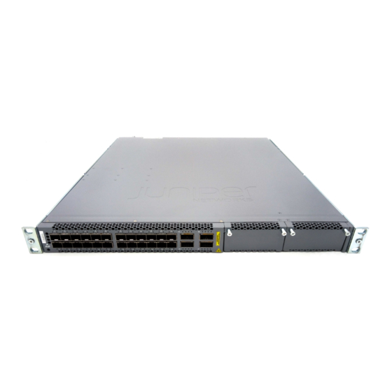
Juniper EX4600 Hardware Manual
Hide thumbs
Also See for EX4600:
- Hardware manual (230 pages) ,
- Quick start manual (13 pages) ,
- Quick start manual (10 pages)
Table of Contents
Advertisement
Quick Links
Advertisement
Table of Contents
Troubleshooting

Related Manuals for Juniper EX4600


Summary of Contents for Juniper EX4600
- Page 1 EX4600 Switch Hardware Guide Published 2022-11-30...
- Page 2 The Juniper Networks product that is the subject of this technical documentation consists of (or is intended for use with) Juniper Networks software. Use of such software is subject to the terms and conditions of the End User License Agreement ("EULA") posted at https:/ /support.juniper.net/support/eula/.
-
Page 3: Table Of Contents
Field-Replaceable Units in an EX4600 Switch | 8 Port Panel of an EX4600 Switch | 9 Access Port and Uplink Port LEDs on an EX4600 Switch | 10 Management Panel of an EX4600 Switch | 13 Chassis Status LEDs on an EX4600 Switch | 16... - Page 4 Rack Requirements for an EX4600 Switch | 52 Cabinet Requirements for an EX4600 Switch | 54 Clearance Requirements for Airflow and Hardware Maintenance for an EX4600 Switch | 56 EX4600 Network Cable and Transceiver Planning | 57 Determining Interface Support for an EX4600 Switch | 57...
- Page 5 Unpacking and Mounting an EX4600 Switch | 71 Installing and Connecting an EX4600 Switch | 71 Unpacking an EX4600 Switch | 72 Mounting an EX4600 Switch in a Rack or Cabinet | 73 Before You Begin Rack Installation | 74 Four Post Procedure | 75...
- Page 6 Locating the Serial Number on an EX4600 Switch or Component | 129 Listing the Chassis and Component Details Using the CLI | 129 Locating the Chassis Serial Number ID Label on an EX4600 Switch | 131 Locating the Serial Number ID Labels on FRU Components | 131...
- Page 7 Definitions of Safety Warning Levels | 138 Qualified Personnel Warning | 140 Warning Statement for Norway and Sweden | 140 Fire Safety Requirements | 141 Installation Instructions Warning | 142 Chassis and Component Lifting Guidelines | 143 Restricted Access Warning | 143 Ramp Warning | 145 Rack-Mounting and Cabinet-Mounting Warnings | 145 Grounded Equipment Warning | 149...
- Page 8 Agency Approvals for EX Series Switches | 173 Compliance Statements for EMC Requirements for EX Series Switches | 174 Compliance Statements for Acoustic Noise for EX Series Switches | 178 Statements of Volatility for Juniper Network Devices | 178...
-
Page 9: About This Guide
Use this guide to install hardware and perform initial software configuration, routine maintenance, and troubleshooting for the EX4600 switch. After completing the installation and basic configuration procedures covered in this guide, refer to the Junos OS documentation for information about further software configuration. -
Page 10: Overview
C HAPTER Overview EX4600 System Overview | 2 EX4600 Chassis | 7 EX4600 Cooling System | 21 EX4600 Power System | 28... -
Page 11: Ex4600 System Overview
• Data center distribution in small, low -density data centers In addition to operating as a standalone switch, the EX4600 switch can act as a member switch in a non- Virtual Chassis , a Virtual Chassis composed entirely of EX4600 switches, as well as participate as mixed member switches in a mixed Virtual Chassis with EX4300 switches. - Page 12 Benefits of the EX4600 Switch Compact solution—The EX4600 switch supports up to 72 10-Gigabit Ethernet ports in a 1 rack unit (1 U) chassis. Intelligent buffer management—EX4600 switches have a total of 12 MB shared buffers. While 25 percent of the total buffer space is dedicated, the rest is shared among all ports and is user configurable.
-
Page 13: Gbe Ports
• QFX-EM-4Q–Adds four additional QSFP+ ports to the chassis. When fully populated with QFX- EM-4Q expansion modules, the EX4600 is equivalent to one with 72 interfaces (24 + 16 + 16 + 16). Figure 2 on page Figure 2: QFX-EM-4Q Expansion Module •... -
Page 14: Ex4600 Switch Models
EX Series switches run the Junos operating system (OS), which provides Layer 2 and Layer 3 switching, routing, and security services. An EX4600 switch ships with Junos OS installed on it. The same Junos OS code base that runs on EX4600 switches also runs on all Juniper Networks QFX Series devices, M Series, MX Series, and T Series routers. -
Page 15: Understanding Redundancy Of Ex4600 Switch Components And Functionality
Understanding Redundancy of EX4600 Switch Components and Functionality The following hardware components provide redundancy on an EX4600 switch: • Power supplies—The EX4600 switch can operate with one power supply. However, all EX4600 switches, except the EX4600-40F-S switch, ship with two power supplies preinstalled for... -
Page 16: Ex4600 Chassis
• Cooling system—All EX4600 switches, except the EX4600-40F-S ship with five fan modules installed. If a fan module fails and leads to the overheating of the chassis, alarms occur and the switch might shut down. -
Page 17: Field-Replaceable Units In An Ex4600 Switch
Field-Replaceable Units in an EX4600 Switch Field-replaceable units (FRUs) are components that you can replace at your site. The EX4600 switch FRUs are hot-insertable and hot-removable: you can remove and replace one of them without powering off the switch or disrupting the switching function. FRU types are: •... -
Page 18: Port Panel Of An Ex4600 Switch
Port Panel of an EX4600 Switch The fixed portion of the port panel of the EX4600-40F switch supports up to a maximum of 40 logical 10 GbE ports. Twenty-four physical ports (0 through 23) support 10 Gbps small form-factor pluggable plus (SFP+) transceivers. -
Page 19: Access Port And Uplink Port Leds On An Ex4600 Switch
Expansion module bays with cover panels (2) — — Access Port and Uplink Port LEDs on an EX4600 Switch The Link/Activity and Status LED configuration for an EX4600 switch uses bi-colored LEDs. The two figures in this topic show the location of those LEDs:... - Page 20 • Figure 5 on page 11 shows the location of the LEDs on the SFP+ access ports on the EX4600 and Figure 6 on page 11 shows the location of the LEDs on the QSFP+ uplink ports on the EX4600.
- Page 21 Table 4: Network Port LEDs on SFP+ Ports on an EX4600 Switch Color State Description Link/Activity Unlit The port is administratively disabled, there is no power, the link is down, or there is a fault. Green On steadily A link is established, but there is no link activity.
-
Page 22: Management Panel Of An Ex4600 Switch
All four LEDs blink to indicate the beacon function was enabled on the port. Management Panel of an EX4600 Switch The management panel of the EX4600 switch is located on the Field Replaceable Unit (FRU) side of the switch, as shown in Figure 7 on page 13. - Page 23 Reset button, see caution statement below — CAUTION: Do not use the Reset button to restart the power sequence unless under the direction of Juniper Networks Technical Assistance Center (JTAC). The management panel consists of the following components: • Status LEDs •...
- Page 24 • SYS (System) • Unlit indicates the switch is powered off or halted. • Solid green indicates that Junos OS for EX Series is loaded on the switch. • Blinking green indicates that the switch is a participating member in a Virtual Chassis. •...
-
Page 25: Chassis Status Leds On An Ex4600 Switch
Chassis Status LEDs on an EX4600 Switch The EX4600 switch has four status LEDs on the field-replaceable unit (FRU) end of the chassis, next to the management ports (see Figure 9 on page 16). Figure 9: Chassis Status LEDs on an EX4600 Switch Status LEDs RJ-45 console port (CON) and em0–RJ-45... - Page 26 Table 6: Chassis Status LEDs on an EX4600 Switch Name Color State Description ALM (Alarm or beacon) Unlit The switch is halted or there is no alarm. On steadily A major hardware fault has occurred, such as a temperature alarm or power failure, and the switch has halted.
-
Page 27: Expansion Modules For The Ex4600
EX4600-EM-8F | 19 QFX-EM-4Q | 20 The EX4600 switch has two bays on the port panel in which you can optionally install one or two expansion modules. The EX4600 supports the same two expansion modules as the QFX5100, which increase port density: •... -
Page 28: Ex4600-Em-8F
The EX4600 is configured for the QFX-EM-4Q by default, but any combination of the two modules is supported. Expansion modules can be hot-inserted or hot-removed. However, when an EX4600-EM-8F is inserted instead of the default QFX-EM-4Q, the new configuration causes the interfaces to temporarily go down. -
Page 29: Qfx-Em-4Q
QFX-EM-4Q The QFX-EM-4Q, provides 4 additional 40-Gigabit Ethernet QSFP+ ports to one of the bays in the EX4600 switch. Port 0 and port 2 can be used for port channelization by configuring the system mode for 104 port mode. Figure 11 on page 20 shows the QFX-EM-4Q ports and LEDs. -
Page 30: Ex4600 Cooling System
Do Not Install Components with Different Airflow or Wattage in the Switch | 25 Fan Module Status | 25 The cooling system in an EX4600 switch consists of five fan modules and a single fan in each power supply. The switch can be set up to work in one of two airflow directions:... - Page 31 • Airflow Out–Air enters the switch through the vents in the port panel. All EX4600 switches, except the EX4600-40F-S, are shipped with five fan modules and two power supplies. Order fans for the EX4600-40F-S separately. CAUTION: Do not mix: • AC and DC power supplies in the same chassis.
- Page 32 AIR OUT . On legacy switches or switches with LCDs, this airflow is also called front-to-back and back-to-front. Table 9 on page 23 lists the available fan module product SKUs and the direction of airflow in them: Table 9: Fan Modules for EX4600 Switches Fan Module Airflow Diagram Label on Color of...
- Page 33 In data center deployments, position the switch in such a manner that the AIR IN labels on switch components are next to the cold aisle, and AIR OUT labels on switch components are next to the hot aisle. Figure 13: Air In Airflow Through EX4600 Switch Chassis Figure 14: Air Out Airflow Through EX4600 Switch Chassis...
- Page 34 However if you need to convert an EX4600 switch to have a different airflow, you can change the airflow pattern. To convert an AIR IN product SKU to an AIR OUT product SKU or an AIR OUT product SKU to a AIR IN product SKU, you must replace all of the fans and power supplies at one time to use the new direction.
- Page 35 The system raises an alarm if a fan module fails or if the ambient temperature inside the chassis rises above the acceptable range. If the temperature inside the chassis rises above the threshold temperature, the system shuts down automatically. SEE ALSO Clearance Requirements for Airflow and Hardware Maintenance for an EX4600 Switch | 56...
-
Page 36: Fan Module Led On An Ex4600 Switch
Fan Module LED on an EX4600 Switch Figure 15 on page 27 shows the location of the LED next to the fan module. Figure 15: Fan Module LED in an EX4600 Switch Fan LED — Table 11 on page 27 describes the function of the fan tray LED. -
Page 37: Ex4600 Power System
The AC power supply is 650 W. It is the same power supply used in Juniper Networks QFX5100 switches. CAUTION: Do not mix power supplies with different airflow or different wattage. The system raises an alarm when a power supply having a different airflow or wattage is inserted into the chassis. - Page 38 Figure 16 on page 29 for an example of the power supply. Figure 16: AC Power Supply in EX4600 Switches Handle AC appliance inlet — — Security latch Ejector lever — — The power supply provides FRU-to-port or port-to-FRU airflow depending on the product SKU you purchase.
- Page 39 Table 12 on page 30 shows the different power supplies and their direction of airflow. Table 12: Airflow Direction in EX4600 and QFX5100 AC Power Supplies Product Number Direction of Airflow...
-
Page 40: Ac Power Supply Leds On An Ex4600 Switch
AC Power Supply LEDs on an EX4600 Switch Figure 18 on page 31 shows the location of the LEDs on the power supply. Figure 18: AC Power Supply LEDs on an EX4600 Switch Table 13 on page 31 describes the LEDs on the AC power supplies. -
Page 41: Ac Power Specifications For An Ex4600 Switch
AC power supply is installed properly, but the power supply has an internal failure. AC Power Specifications for an EX4600 Switch Table 14 on page 32 describes the AC power specifications for an EX4600 switch. Table 14: AC Power Specifications for an EX4600 Switch Item... - Page 42 National Electrical Code (NEC) Sections 400-8 (NFPA 75, 5-2.2) and 210-52 and Canadian Electrical Code (CEC) Section 4-010(3). The cords that can be ordered for the EX4600 switch are in compliance. Table 15 on page 33 lists AC power cord specifications provided for each country or region.
-
Page 43: Dc Power Supply In An Ex4600 Switch
CBL-EX-PWR-C13- DC Power Supply in an EX4600 Switch Except for the EX4600-40F-S switch, the EX4600 is shipped from the factory with two power supplies pre-installed. Each power supply is a hot-removable and hot-insertable field-replaceable unit (FRU) when the second power supply is installed and running. You can install replacement power supplies in the two slots next to the fan modules without powering off the switch or disrupting the switching function. - Page 44 The DC power supply is 650 W with dual feeds for power resiliency. It is same power supply that is used in the Juniper Networks QFX5100 line of switches (see Figure 19 on page 35). Figure 19: DC Power Supply in EX4600 and QFX5100 Switches Terminal block Ejector lever —...
- Page 45 To supply sufficient power, terminate the DC input wiring on a facility DC source that is capable of supplying a minimum of 7 A at –48 VDC. To avoid electrical injury, carefully follow instructions in "Installing a Power Supply in an EX4600 Switch" on page 100 "Removing a Power Supply from an EX4600 Switch" on page...
-
Page 46: Dc Power Supply Leds In Ex4600 Switches
Connecting DC Power to an EX4600 Switch | 81 DC Power Supply LEDs in EX4600 Switches Figure 21 on page 37 shows the location of the LEDs on the DC power supply. Figure 21: DC Power Supply Faceplate on an EX4600 Switch Input LED Fault LED —... -
Page 47: Dc Power Specifications For An Ex4600 Switch
DC Power Specifications for an EX4600 Switch Table 17 on page 38 describes the DC power specifications for DC product SKUs of the EX4600 switch. Table 17: DC Power Specifications for an EX4600 Switch Item... -
Page 48: Grounding Cable And Lug Specifications For An Ex4600 Switch
• A protective earthing terminal bracket is provided in the accessory kit for connecting the switch to earth ground. This L-shaped bracket attaches to the side of the EX4600 chassis through the mounting bracket, providing a protective earthing terminal for the switch. - Page 49 • The grounding cable that you provide for a EX4600 must be 14 AWG (2 mm²), minimum 60° C wire, or as permitted by the local code. • Ensure you have two SAE 10-32 washers and screws to attach the cable and bracket (not provided).
-
Page 50: Site Planning, Preparation, And Specifications
C HAPTER Site Planning, Preparation, and Specifications Site Preparation Checklist for an EX4600 Switch | 42 EX4600 Site Guidelines and Requirements | 43 EX4600 Network Cable and Transceiver Planning | 57 EX4600 Management Cable Specifications and Pinouts | 66... -
Page 51: Site Preparation Checklist For An Ex4600 Switch
Site Preparation Checklist for an EX4600 Switch The checklist in Table 18 on page 42 summarizes the tasks you need to perform when preparing a site for EX4600 switch installation. Table 18: Site Preparation Checklist Item or Task For More Information... -
Page 52: Ex4600 Site Guidelines And Requirements
Plan the cable routing and management. RELATED DOCUMENTATION General Safety Guidelines and Warnings General Site Guidelines Installing and Connecting an EX4600 Switch | 71 EX4600 Site Guidelines and Requirements IN THIS SECTION Environmental Requirements and Specifications for EX Series Switches | 44... -
Page 53: Environmental Requirements And Specifications For Ex Series Switches
Cabinet Requirements for an EX4600 Switch | 54 Clearance Requirements for Airflow and Hardware Maintenance for an EX4600 Switch | 56 Environmental Requirements and Specifications for EX Series Switches The switch must be installed in a rack or cabinet housed in a dry, clean, well-ventilated, and temperature-controlled environment. - Page 54 (Continued) Table 19: EX Series Switch Environmental Tolerances Switch or Environment Tolerance device Altitude Relative Humidity Temperature Seismic No performance Normal operation Normal operation ensured Complies with EX2200 degradation up to ensured in the relative in the temperature range Zone 4 (except 10,000 feet humidity range 10%...
- Page 55 (Continued) Table 19: EX Series Switch Environmental Tolerances Switch or Environment Tolerance device Altitude Relative Humidity Temperature Seismic No performance Normal operation Normal operation ensured Complies with EX3400 degradation up to ensured in the relative in the temperature range Zone 4 10,000 feet humidity range 10% 32°...
- Page 56 F (45° C) • EX4550-32T switches — Normal operation is ensured in the temperature range 32° F through 104° F (40° C) EX4600 No performance Normal operation Complies with • Normal operation degradation to ensured in the relative Zone 4...
- Page 57 (Continued) Table 19: EX Series Switch Environmental Tolerances Switch or Environment Tolerance device Altitude Relative Humidity Temperature Seismic No performance Normal operation Normal operation is Complies with EX4650 degradation to ensured in the relative ensured in the Zone 4 6,000 feet humidity range 10% temperature range 32°...
- Page 58 (Continued) Table 19: EX Series Switch Environmental Tolerances Switch or Environment Tolerance device Altitude Relative Humidity Temperature Seismic No performance Normal operation Normal operation is Complies with EX9204 degradation up to ensured in the relative ensured in the Zone 4 10,000 feet humidity range 5% temperature range 32°...
-
Page 59: General Site Guidelines
(Continued) Table 19: EX Series Switch Environmental Tolerances Switch or Environment Tolerance device Altitude Relative Humidity Temperature Seismic No performance Normal operation Normal operation ensured Complies with EX9251 degradation up to ensured in relative in temperature range of Telcordia The maximum 10,000 ft humidity range of 5% to 32°... -
Page 60: Site Electrical Wiring Guidelines
• Follow the prescribed electrostatic discharge (ESD) prevention procedures to prevent damaging the equipment. Static discharge can cause components to fail completely or intermittently over time. • Install the device in a secure area, so that only authorized personnel can access the device. Site Electrical Wiring Guidelines Table 20 on page 51 describes the factors you must consider while planning the electrical wiring at... -
Page 61: Rack Requirements For An Ex4600 Switch
• Electrical hazards as a result of power surges conducted over the lines into the equipment. Rack Requirements for an EX4600 Switch EX4600 Switches are designed to be installed on four-post racks. Rack requirements consist of: • Rack type • Mounting bracket hole spacing •... - Page 62 (Continued) Table 21: Rack Requirements for the EX4600 Switch Rack Requirement Guidelines Mounting bracket hole The holes in the mounting brackets are spaced at 1 U (1.75 in. or 4.45 cm), so that the spacing switch can be mounted in any rack that provides holes spaced at that distance.
-
Page 63: Cabinet Requirements For An Ex4600 Switch
Rack-Mounting and Cabinet-Mounting Warnings | 145 Cabinet Requirements for an EX4600 Switch You can mount the EX4600 switch in a cabinet that contains a four-post 19-in. rack as defined in Cabinets, Racks, Panels, and Associated Equipment (document number EIA-310-D) published by the Electronics Industry Association. - Page 64 • The EX4600 fans exhaust hot air either through the vents on the port panel or through the fans and power supplies. Install the switch in the cabinet in a way that maximizes the open space on the FRU side of the chassis. This maximizes the clearance for critical airflow.
-
Page 65: Clearance Requirements For Airflow And Hardware Maintenance For An Ex4600 Switch
• Leave at least 24 in. (61 cm) both in front of and behind the EX4600 switch. For service personnel to remove and install hardware components, you must leave adequate space at the front and back of the switch. -
Page 66: Ex4600 Network Cable And Transceiver Planning
EX4600 switch can be configured to operate as 10-Gigabit Ethernet interface by using a breakout cable or as a single 40-Gigabit Ethernet interface. The ports on an EX4600 switch are disabled by default. You enable a port through the CLI. -
Page 67: Cable Specifications For Qsfp+ Transceivers On Ex4600 Series Switches
The Hardware Compatibility Tool enables you to search by product, displaying all the transceivers supported on that device, or category, by interface speed or type. The list of supported transceivers for the EX4600 is located at https:/ /pathfinder.juniper.net/hct/product/#prd=EX4600. - Page 68 Table 23 on page 59 describes the signals on each fiber. Table 24 on page 59 shows the pin-to-pin connections for proper polarity. Table 23: QSFP+ MPO Cable Signals Fiber Signal Tx0 (Transmit) Tx1 (Transmit) Tx2 (Transmit) Tx3 (Transmit) Unused Unused Unused Unused...
-
Page 69: Network Cable Specifications For Ex4600 Switches
Table 24: QSFP+ MPO Fiber-Optic Crossover Cable Pinouts Network Cable Specifications for EX4600 Switches EX4600 switches have interfaces that use various types of network cables. Table 25 on page 61 lists the specifications for the cables that connect the console (CON) and... -
Page 70: Overview Of Ex Series Switches: Fiber-Optic Cable Signal Loss, Attenuation, And Dispersion
NOTE: The EX4600 can be configured with SFP management ports that support 1000BASE-SX transceivers. Table 25: Cable Specifications for Switch-to-Management-Device Connections Ports on Cable Cable/Wire Maximum Switch Additional EX4600 Specification Supplied Length Receptacle Information Switches RJ-45 Console RS-232 One 7-foot 7 ft (2.13 m) - Page 71 To determine the power budget and power margin needed for fiber-optic connections, you need to understand how signal loss, attenuation, and dispersion affect transmission. EX Series switches use various types of network cables, including multimode and single-mode fiber-optic cable. Signal Loss in Multimode and Single-Mode Fiber-Optic Cable Multimode fiber is large enough in diameter to allow rays of light to reflect internally (bounce off the walls of the fiber).
-
Page 72: Calculate The Fiber-Optic Cable Power Budget For Ex Series Devices
For single-mode transmission, modal dispersion is not a factor. However, at higher bit rates and over longer distances, chromatic dispersion limits the maximum link length. An efficient optical data link must have enough light to exceed the minimum power that the receiver requires to operate within its specifications. -
Page 73: Calculating The Fiber-Optic Cable Power Margin For Ex Series Devices
Calculating the Fiber-Optic Cable Power Margin for EX Series Devices Calculating the Fiber-Optic Cable Before calculating the power margin, calculate the power budget (see Power Budget for EX Series Devices Calculate the link's power margin when planning fiber-optic cable layout and distances to ensure that fiber-optic connections have sufficient signal power to overcome system loss and still satisfy the minimum input requirements of the receiver for the required performance level. - Page 74 (Continued) Table 26: Estimated Values for Factors Causing Link Loss Link-Loss Factor Estimated Link-Loss Value Sample (LL) Calculation Values Splice 0.5 dBm This example assumes 2 splices. Loss for two splices: (2) * (0.5 dBm) = 1 dBm Fiber attenuation This example assumes the link is 2 •...
-
Page 75: Ex4600 Management Cable Specifications And Pinouts
EX4600 Management Cable Specifications and Pinouts IN THIS SECTION Cable Specifications for Console and Management Connections for the EX4600 | 66 USB Port Specifications for an EX Series Switch | 67 Console Port Connector Pinout Information | 68 RJ-45 Management Port Connector Pinout Information | 69... -
Page 76: Usb Port Specifications For An Ex Series Switch
RJ-45 patch cable (100 meters) 1000BASE-T operation USB Port Specifications for an EX Series Switch Juniper Networks tested and officially supports the following USB flash drives for the USB port on all EX Series switches: • RE-USB-1G-S • RE-USB-2G-S •... -
Page 77: Console Port Connector Pinout Information
Console Port Connector Pinout Information The console port on a Juniper Networks device is an RS-232 serial interface that uses an RJ-45 connector to connect to a console management device. The default baud rate for the console port is 9600 baud. -
Page 78: Rj-45 Management Port Connector Pinout Information
RJ-45 Management Port Connector Pinout Information Table 29 on page 69 provides the pinout information for the RJ-45 connector for the management port on Juniper Networks devices. Table 29: RJ-45 Management Port Connector Pinout Information Signal Description TRP1+ Transmit/receive data pair 1... -
Page 79: Initial Installation And Configuration
C HAPTER Initial Installation and Configuration Unpacking and Mounting an EX4600 Switch | 71 Connecting the EX4600 to Power | 77 Connecting the EX4600 to Management Devices | 87 Configuring Junos OS on the EX4600 | 91... -
Page 80: Unpacking And Mounting An Ex4600 Switch
IN THIS SECTION Installing and Connecting an EX4600 Switch | 71 Unpacking an EX4600 Switch | 72 Mounting an EX4600 Switch in a Rack or Cabinet | 73 Installing and Connecting an EX4600 Switch You can mount an EX4600 switch: •... -
Page 81: Unpacking An Ex4600 Switch
Unpacking an EX4600 Switch The EX4600 switch chassis is a rigid sheet-metal structure that houses the hardware components. A EX4600 switch is shipped in a cardboard carton, secured with foam packing material. The carton also contains an accessory box. CAUTION: EX4600 switches are maximally protected inside the shipping carton. Do not unpack the switch until you are ready to begin installation. -
Page 82: Mounting An Ex4600 Switch In A Rack Or Cabinet
Before You Begin Rack Installation | 74 Four Post Procedure | 75 You can mount the EX4600 switch on a four post 19-in. rack or cabinet using the mounting kit provided with the device. For four post rack or cabinet installations, the mounting kit contains two front mounting rails with two matching rear mounting blades. -
Page 83: Before You Begin Rack Installation
Optional equipment: Grounding cable kit with bracket, lug, and three nuts with integrated washers. WARNING: The EX4600 switch must be supported at all four corners. Mounting the chassis using only the front brackets will damage the chassis and can result in serious... -
Page 84: Four Post Procedure
CAUTION: The EX4600 require two people for installation. If you are installing the EX4600 switch above 60 in. (152.4 cm) from the floor, you can remove the power supplies and fan modules to minimize the weight before attempting to install the switch. - Page 85 Figure 26 on page Figure 26: Slide Mounting Blade into EX4600 Mounting Rail 9. Ensure that the switch chassis is level by verifying that all the screws on the front of the rack are aligned with the screws at the back of the rack.
-
Page 86: Connecting The Ex4600 To Power
• Protective earthing terminal bracket—This bracket attaches to the EX4600 switch chassis through the left front mounting bracket, providing a protective earthing terminal for the switch. • Grounding cable for your EX4600 switch—The grounding cable must be 14 AWG (2 mm²), minimum 90° C wire, or as permitted by the local code. - Page 87 Figure 27 on page Figure 27: Connecting a Grounding Cable to an EX4600 Switch 4. Dress the grounding cable and ensure that it does not touch or block access to other device components and that it does not drape where people could trip over it.
-
Page 88: Connecting Ac Power To An Ex4600 Switch
For instructions on connecting earth ground, see EX Series Switch • Install the power supply in the chassis. For instructions on installing a power supply in an EX4600 switch, see "Installing a Power Supply in an EX4600 Switch" on page 100. - Page 89 5. Push the power cord retainer onto the power cord (see Figure 28 on page 80). Figure 28: Connecting an AC Power Cord to an AC Power Supply in an EX4600 Switch Power cord retainer — 6. If the AC power source outlet has a power switch, set it to the OFF (O) position.
-
Page 90: Connecting Dc Power To An Ex4600 Switch
For instructions on connecting earth ground, see "Connecting Earth Ground to an EX4600 Switch" on page • Install the power supply in the chassis. For instructions on installing a power supply in an EX4600 switch, see "Installing a Power Supply in an EX4600 Switch" on page 100. - Page 91 WARNING: DC-powered EX4600 switches are intended for installation only in a restricted access location. NOTE: The battery returns of the DC power supply should be connected as an isolated DC return (DC-I). To connect DC power to an EX4600 switch: Attach the grounding strap to your bare wrist and to a site ESD point.
- Page 92 NOTE: Do not overheat the tubing. Figure 29: How to Install Heat-Shrink Tubing Ensure that the input circuit breaker is open so that the voltage across the DC power source cable leads is 0 V and that the cable leads do not become active while you are connecting DC power. NOTE: The V+ terminals are referred to as +RTN, and V–...
- Page 93 Figure 30 on page 85 Figure 31 on page 86 The EX4600 is designed to operate with a DC power supply that has a single, non-redundant, feed input. For source redundancy, two DC power supplies must be installed in EX4600; connect source (A) to one power supply and connect source (B) to the second power supply.
- Page 94 Tighten the screws on the power supply terminals until snug using the screwdriver. Do not overtighten—apply between 5 in-lb (0.56 Nm) and 6 in-lb (0.68 Nm) of torque to the screws. Figure 30: DC Power Supply Faceplate for an EX4600 Switch Shunt negative input terminals (-48V) ESD grounding point —...
- Page 95 Do not connect the terminals to different sources. Figure 31: Securing Ring Lugs to the Terminals on the EX4600 DC Power Supply Replace the terminal block cover. 10. Close the input circuit breaker.
-
Page 96: Connecting The Ex4600 To Management Devices
Connect a Device to a Network for Out-of-Band Management | 87 Connect a Device to a Management Console Using an RJ-45 Connector | 88 Connecting EX4600 Switches in a Virtual Chassis | 89 Connect a Device to a Network for Out-of-Band Management Ensure that you have an Ethernet cable that has an RJ-45 connector at either end. -
Page 97: Connect A Device To A Management Console Using An Rj-45 Connector
2. Connect the other end of the Ethernet cable to the management device. Figure 33: Connect a Device to a Network for Out-of-Band Management Connect a Device to a Management Console Using an RJ-45 Connector Ensure that you have an Ethernet cable that has an RJ-45 connector at either end. One such cable and an RJ-45-to-DB-9 serial port adapter are supplied with the device. -
Page 98: Connecting Ex4600 Switches In A Virtual Chassis
Connecting EX4600 Switches in a Virtual Chassis EX4600 switches can be cabled together to create a Virtual Chassis in a ring topology. Each Virtual Chassis can have up to 10 switches (members) participating in the ring. The Virtual Chassis can be comprised of all EX4600 switches filling the primary Routing Engine (RE), backup RE, and linecard roles. - Page 99 EX4600 and EX4300. Ensure all members of the Virtual Chassis are running the same Junos OS Release by issuing the show chassis version CLI command. See for a diagram of how to cable two EX4600 switches and two EX4300 switches into a Virtual Chassis for Junos OS Release 14.1X53-D25 and later.
-
Page 100: Configuring Junos Os On The Ex4600
• Parity—None • Stop Bits—1 • DCD State—Disregard You must perform the initial configuration of the EX4600 switch through the console port using the command-line interface (CLI). To connect and configure the switch from the console: Connect the console port to a laptop or PC using the supplied RJ-45 cable and RJ-45 to DB-9 adapter. - Page 101 NOTE: The management ports, em0 (C0) and em1 (C1) are found on the management panel of the EX4600 switch. (Optional) Configure the static routes to remote prefixes with access to the management port.
- Page 102 NOTE: When Telnet is enabled, you cannot log in to the EX4600 switch through Telnet using root credentials. Root login is allowed only for SSH access. 11. Commit the configuration to activate it on the switch. [edit] root@# commit RELATED DOCUMENTATION...
-
Page 103: Maintaining Components
Maintaining Components Maintaining the EX4600 Switch Cooling System | 95 Maintaining the EX4600 Switch Power System | 98 Maintaining the Expansion Module in an EX4600 Switch | 102 Maintain Transceivers | 106 Maintain Fiber-Optic Cables | 111 Removing the EX4600 Switch | 114... -
Page 104: Maintaining The Ex4600 Switch Cooling System
Prevention of Electrostatic Discharge precautions to prevent electrostatic discharge (ESD) damage (see Damage Ensure that you have the following parts and tools available to remove a fan module from an EX4600 switch: • ESD grounding strap • Antistatic bag or an antistatic mat... -
Page 105: Installing A Fan Module In An Ex4600 Switch
Cooling System and Airflow in an EX4600 Switch | 21 Installing a Fan Module in an EX4600 Switch Before you install a fan module in an EX4600 switch, ensure that you have taken the necessary Prevention of Electrostatic Discharge precautions to prevent electrostatic discharge (ESD) damage (see... - Page 106 The fan modules are designed so that they can only be inserted into the EX4600 switch product SKU that supports the same airflow type. See "Cooling System and Airflow in an EX4600 Switch" on page 21 for more information.
-
Page 107: Maintaining The Ex4600 Switch Power System
Prevention of Electrostatic Discharge precautions to prevent electrostatic discharge (ESD) damage (see Damage Ensure that you have the following parts and tools available to remove a power supply from an EX4600 switch: • ESD grounding strap • Antistatic bag or an antistatic mat •... - Page 108 NOTE: If only one power supply is installed in your EX4600 switch, you need to power off the switch before removing the power supply. See "Powering Off an EX4600 Switch" on page 115. 3. Disconnect power to the switch: • AC power supply—If the AC power source outlet has a power switch, set it to the OFF (O) position.
-
Page 109: Installing A Power Supply In An Ex4600 Switch
AC Power Supply in an EX4600 Switch | 28 Installing a Power Supply in an EX4600 Switch • Before you install a power supply in an EX4600 switch, ensure that you have taken the necessary Prevention of Electrostatic precautions to prevent electrostatic discharge (ESD) damage (see Discharge Damage •... - Page 110 A to one power supply and power source feed B to the second power supply. CAUTION: Do not connect feed A and feed B to the same power supply input terminal. NOTE: If you have a Juniper Care service contract, register any addition, change, or upgrade of hardware components at https:/ /www.juniper.net/customers/support/tools/updateinstallbase/...
-
Page 111: Maintaining The Expansion Module In An Ex4600 Switch
(FRUs): You can remove and replace them without powering off the switch. The EX4600 is configured for the QFX-EM-4Q by default, but any combination of the two modules is supported. Expansion modules can be hot-inserted or hot-removed. However, when an EX4600-EM-8F is inserted instead of the default QFX-EM-4Q, the PFE reboots and all of the interfaces on the switch and expansion module temporarily go down. - Page 112 If you do not wait for at least 5 seconds, the interfaces on the expansion module might not come up. Figure 42 on page 103 shows removing a QFX-EM-4Q expansion module from the port panel of a EX4600 switch. Figure 42: Removing a QFX-EM-4Q Expansion Module from an EX4600 Switch...
-
Page 113: Installing An Expansion Module In An Ex4600 Switch
• Phillips (+) screwdriver, number 2 The EX4600 switch allows up to two expansion modules to be added to the port panel to increase port density. The EX4600 switch holds two bays of expansion modules that can be mixed and matched as desired. - Page 114 ST LED turns green, the expansion module is ready for use. Figure 43 on page 105 shows how to install a QSFP+ expansion module on the port panel of a EX4600 switch. Figure 43: Installing a QFX4Q Expansion Module in an EX4600 Switch...
-
Page 115: Maintain Transceivers
• Rubber safety caps to cover the transceiver and fiber-optic cable connector • A dust cover to cover the port or a replacement transceiver The transceivers for Juniper Networks devices are hot-removable and hot-insertable field-replaceable units (FRUs). You can remove and replace them without powering off the device or disrupting device functions. - Page 116 2. Wrap and fasten one end of the ESD wrist strap around your bare wrist, and connect the other end of the strap to the ESD point on the switch. 3. Label the cable connected to the transceiver so that you can reconnect it correctly. LASER WARNING: Do not look directly into a fiber-optic transceiver or into the ends of fiber-optic cables.
-
Page 117: Install A Transceiver
b. Grasp the transceiver ejector lever and gently slide the transceiver approximately 0.5 in. (1.3 cm) straight out of the port. CAUTION: To prevent ESD damage to the transceiver, do not touch the connector pins at the end of the transceiver. Figure 44: Remove a QSFP+ Transceiver Ejector lever —... - Page 118 Juniper Networks. If you face a problem running a Juniper device that uses third-party optical modules or cables, JTAC may help you diagnose host-related issues if the observed issue is not, in the opinion of JTAC, related to the use of the third-party optical modules or cables.
- Page 119 3. Check to see whether the transceiver is covered with a rubber safety cap. If it is not, cover the transceiver with a rubber safety cap. LASER WARNING: Do not leave a fiber-optic transceiver uncovered except when inserting or removing a cable. The rubber safety cap keeps the port clean and protects your eyes from accidental exposure to laser light.
-
Page 120: Maintain Fiber-Optic Cables
CAUTION: Do not let fiber-optic cable hang free from the connector. Do not allow fastened loops of cable to dangle, which stresses the cable at the fastening point. CAUTION: Avoid bending fiber-optic cable beyond its minimum bend radius. An arc smaller than a few inches in diameter can damage the cable and cause problems that are difficult to diagnose. -
Page 121: Connect A Fiber-Optic Cable
Connect a Fiber-Optic Cable Before you connect a fiber-optic cable to an optical transceiver installed in a device, ensure that you Laser and LED Safety Guidelines have taken the necessary precautions for safe handling of lasers (see and Warnings To connect a fiber-optic cable to an optical transceiver installed in a device: LASER WARNING: Do not look directly into a fiber-optic transceiver or into the ends of fiber-optic cables. -
Page 122: Disconnect A Fiber-Optic Cable
• A rubber safety cap to cover the transceiver • A rubber safety cap to cover the fiber-optic cable connector Juniper Networks devices have optical transceivers to which you can connect fiber-optic cables. To disconnect a fiber-optic cable from an optical transceiver installed in the device: 1. -
Page 123: Removing The Ex4600 Switch
Fiber Cleaner. Follow the instructions in the cleaning kit you use. Removing the EX4600 Switch IN THIS SECTION Installing and Removing EX4600 Switch Hardware Components | 115 Powering Off an EX4600 Switch | 115 Removing an EX4600 Switch from a Rack or Cabinet | 118... -
Page 124: Installing And Removing Ex4600 Switch Hardware Components
. To remove an SFP+ or QSFP+ transceiver from an EX4600 switch, follow the instructions in Remove a Transceiver To connect a fiber-optic cable to an SFP+ or QSFP+ transceiver in an EX4600 switch, follow the Connect a Fiber-Optic Cable instructions in . - Page 125 To power off an EX4600 switch: 1. Connect to the switch using one of the following methods: • Connect a management device to the console (CON) port on a EX4600 switch. For instructions about connecting a management device to the console (CON) port, see...
- Page 126 Syncing disks, vnodes remaining...0 0 0 0 done syncing disks... All buffers synced. Uptime: 11h0m30s Normal shutdown (no dump device defined) unloading fpga driver unloading fx-scpld Powering system off using ACPI kvm: 28646: cpu0 disabled perfctr wrmsr: 0xc1 data 0xabcd pci-stub 0000:01:00.2: transaction is not cleared;...
-
Page 127: Removing An Ex4600 Switch From A Rack Or Cabinet
• Ensure that the rack is stable and secured to the building. • Ensure that there is enough space to place the removed EX4600 switch in its new location and along the path to the new location. - Page 128 2. Remove the EX4600 switch from the rack or cabinet. 3. Use the screwdriver to remove the mounting screws that attach the mounting blades attached to the rear of the rack or cabinet.
-
Page 129: Troubleshooting Hardware
C HAPTER Troubleshooting Hardware Troubleshooting the EX4600 Components | 121... -
Page 130: Troubleshooting The Ex4600 Components
NOTE: This topic applies only to the J-Web Application package. Alarms alert you to conditions that might prevent normal operation of the switch. Before monitoring alarms on a Juniper Networks EX Series Ethernet switch, become familiar with the terms defined in Table 31 on page 121. - Page 131 (Continued) Table 31: Alarm Terms Term Definition system alarm Preset alarm triggered by a missing rescue configuration or failure to install a license for a licensed software feature. NOTE: On EX6200 switches, a system alarm can be triggered by an internal link error. Alarm Types The switch supports these alarms: •...
-
Page 132: Interface Alarm Messages
NOTE: Fibre Channel alarms are valid only on QFX3500 devices. NOTE: When red alarms or major alarms are issued on QFX5100 or EX4600 switches, the alarm LED glows amber instead of red. - Page 133 router, or any PC or laptop that supports Linux. The steps you take to create the emergency boot device vary, depending on the device. To create an emergency boot device: 1. Use FTP to copy the installation media image into the /var/tmp directory on the device. 2.
-
Page 134: Performing A Recovery Installation
2. Copy the existing configuration in the file /config/juniper.conf.gz from the device to a remote system, such as a server, or to an emergency boot device. For extra safety, you can also copy the n , where n is a number from 0 through 9) backup configurations (the files named /config/juniper.conf. - Page 135 4. Select Install Junos to format the internal flash storage and install the Junos OS on the emergency boot device onto the internal flash storage. 5. The device copies the software from the emergency boot device, occasionally displaying status messages. Copying the software can take up to 12 minutes. When the software is finished being copied from the emergency device to the device, the device then reboots from the internal flash storage on which the software was just installed.
-
Page 136: Contacting Customer Support And Returning The Chassis Or Components
C HAPTER Contacting Customer Support and Returning the Chassis or Components Returning an EX4600 Chassis or Components | 128... -
Page 137: Returning An Ex4600 Chassis Or Components
Packing an EX4600 Switch or Component for Shipping | 133 Returning an EX4600 Switch or Component for Repair or Replacement If you need to return an EX4600 switch or component to Juniper Networks for repair or replacement, follow this procedure: 1. -
Page 138: Locating The Serial Number On An Ex4600 Switch Or Component
If you are returning a switch or component to Juniper Networks for repair or replacement, you must locate the serial number of the switch or component. You must provide the serial number to the Juniper Networks Technical Assistance Center (JTAC) when you contact them to obtain a Return Materials Contact Customer Support to Obtain Return Material Authorization Authorization (RMA). - Page 139 Fan Tray 4 QFX5100 Fan Tray 4, Front to Back Airflow - AFO {master:0} root@RIDGE_IEEE> root@RIDGE_IEEE> show version fpc0: NOTE: The EX4600 and QFX5100 use the same fan modules. These modules are represented in CLI output as QFX5100 fan trays.
-
Page 140: Locating The Chassis Serial Number Id Label On An Ex4600 Switch
The location for the chassis serial number ID label is found to the right of the 40 Gigabit Ethernet ports. Figure 47 on page 131 for an example of where to find the serial number ID on the EX4600 switch. Figure 47: Location of the Serial Number ID Label on an EX4600 Switch... -
Page 141: Contact Customer Support To Obtain A Return Material Authorization
Contact Customer Support to Obtain a Return Material Authorization If you need to return a device or hardware component to Juniper Networks for repair or replacement, obtain a Return Material Authorization (RMA) number from Juniper Networks Technical Assistance Center (JTAC). You must obtain an RMA number before you attempt to return the component. -
Page 142: Packing An Ex4600 Switch Or Component For Shipping
Packing an EX4600 Switch for Shipping | 133 Packing EX4600 Switch Components for Shipping | 134 If you are returning an EX4600 switch or component to Juniper Networks for repair or replacement, pack the item as described in this topic. -
Page 143: Packing Ex4600 Switch Components For Shipping
Place the packing foam on top of and around the switch. If you are returning accessories or FRUs with the switch, pack them as instructed in "Packing EX4600 Switch Components for Shipping" on page 134. Replace the accessory box on top of the packing foam. -
Page 144: Safety And Compliance Information
C HAPTER Safety and Compliance Information General Safety Guidelines and Warnings | 137 Definitions of Safety Warning Levels | 138 Qualified Personnel Warning | 140 Warning Statement for Norway and Sweden | 140 Fire Safety Requirements | 141 Installation Instructions Warning | 142 Chassis and Component Lifting Guidelines | 143 Restricted Access Warning | 143 Ramp Warning | 145... - Page 145 TN Power Warning | 172 Agency Approvals for EX Series Switches | 173 Compliance Statements for EMC Requirements for EX Series Switches | 174 Compliance Statements for Acoustic Noise for EX Series Switches | 178 Statements of Volatility for Juniper Network Devices | 178...
-
Page 146: General Safety Guidelines And Warnings
General Safety Guidelines and Warnings The following guidelines help ensure your safety and protect the device from damage. The list of guidelines might not address all potentially hazardous situations in your working environment, so be alert and exercise good judgment at all times. •... -
Page 147: Definitions Of Safety Warning Levels
• Some parts of the chassis, including AC and DC power supply surfaces, power supply unit handles, SFB card handles, and fan tray handles might become hot. The following label provides the warning for hot surfaces on the chassis: • Always ensure that all modules, power supplies, and cover panels are fully inserted and that the installation screws are fully tightened. - Page 148 Waarschuwing Dit waarschuwingssymbool betekent gevaar. U verkeert in een situatie die lichamelijk letsel kan veroorzaken. Voordat u aan enige apparatuur gaat werken, dient u zich bewust te zijn van de bij elektrische schakelingen betrokken risico's en dient u op de hoogte te zijn van standaard maatregelen om ongelukken te voorkomen. Varoitus Tämä...
-
Page 149: Qualified Personnel Warning
Qualified Personnel Warning WARNING: Only trained and qualified personnel should install or replace the device. Waarschuwing Installatie en reparaties mogen uitsluitend door getraind en bevoegd personeel uitgevoerd worden. Varoitus Ainoastaan koulutettu ja pätevä henkilökunta saa asentaa tai vaihtaa tämän laitteen. Avertissement Tout installation ou remplacement de l'appareil doit être réalisé... -
Page 150: Fire Safety Requirements
In addition, you should establish procedures to protect your equipment in the event of a fire emergency. Juniper Networks products should be installed in an environment suitable for electronic equipment. We recommend that fire suppression equipment be available in the event of a fire in the vicinity of the equipment and that all local fire, safety, and electrical codes and ordinances be observed when you install and operate your equipment. -
Page 151: Installation Instructions Warning
NOTE: To keep warranties effective, do not use a dry chemical fire extinguisher to control a fire at or near a Juniper Networks device. If a dry chemical fire extinguisher is used, the unit is no longer eligible for coverage under a service agreement. -
Page 152: Chassis And Component Lifting Guidelines
Chassis and Component Lifting Guidelines • Before moving the device to a site, ensure that the site meets the power, environmental, and clearance requirements. • Before lifting or moving the device, disconnect all external cables and wires. • As when lifting any heavy object, ensure that your legs bear most of the weight rather than your back. - Page 153 Avertissement Cet appareil est à installer dans des zones d'accès réservé. Ces dernières sont des zones auxquelles seul le personnel de service peut accéder en utilisant un outil spécial, un mécanisme de verrouillage et une clé, ou tout autre moyen de sécurité. L'accès aux zones de sécurité...
-
Page 154: Ramp Warning
Ramp Warning WARNING: When installing the device, do not use a ramp inclined at more than 10 degrees. Waarschuwing Gebruik een oprijplaat niet onder een hoek van meer dan 10 graden. Varoitus Älä käytä sellaista kaltevaa pintaa, jonka kaltevuus ylittää 10 astetta. Avertissement Ne pas utiliser une rampe dont l'inclinaison est supérieure à... - Page 155 Les directives ci-dessous sont destinées à assurer la protection du personnel: • Le rack sur lequel est monté le Juniper Networks switch doit être fixé à la structure du bâtiment.
- Page 156 Le seguenti direttive vengono fornite per garantire la sicurezza personale: • Il Juniper Networks switch deve essere installato in un telaio, il quale deve essere fissato alla struttura dell'edificio. • Questa unità deve venire montata sul fondo del supporto, se si tratta dell'unica unità...
- Page 157 Para garantizar su seguridad, proceda según las siguientes instrucciones: • El Juniper Networks switch debe instalarse en un bastidor fijado a la estructura del edificio. • Colocar el equipo en la parte inferior del bastidor, cuando sea la única unidad en el...
-
Page 158: Grounded Equipment Warning
Följande riktlinjer ges för att trygga din säkerhet: • Juniper Networks switch måste installeras i en ställning som är förankrad i byggnadens struktur. • Om denna enhet är den enda enheten på ställningen skall den installeras längst ned på... -
Page 159: Laser And Led Safety Guidelines And Warnings
Class 1 LED Product Warning | 152 Laser Beam Warning | 152 Juniper Networks devices are equipped with laser transmitters, which are considered a Class 1 Laser Product by the U.S. Food and Drug Administration and are evaluated as a Class 1 Laser Product per IEC/EN 60825-1 requirements. - Page 160 General Laser Safety Guidelines When working around ports that support optical transceivers, observe the following safety guidelines to prevent eye injury: • Do not look into unterminated ports or at fibers that connect to unknown sources. • Do not examine unterminated optical ports with optical instruments. •...
- Page 161 Class 1 LED Product Warning LASER WARNING: Class 1 LED product. Waarschuwing Klasse 1 LED-product. Varoitus Luokan 1 valodiodituote. Avertissement Alarme de produit LED Class I. Warnung Class 1 LED-Produktwarnung. Avvertenza Avvertenza prodotto LED di Classe 1. Advarsel LED-produkt i klasse 1. Aviso Produto de classe 1 com LED.
-
Page 162: Radiation From Open Port Apertures Warning
Aviso Não olhe fixamente para o raio, nem olhe para ele directamente com instrumentos ópticos. ¡Atención! No mirar fijamente el haz ni observarlo directamente con instrumentos ópticos. Varning! Rikta inte blicken in mot strålen och titta inte direkt på den genom optiska instrument. -
Page 163: Maintenance And Operational Safety Guidelines And Warnings
EXposição à radiação e não deverá olhar fixamente para orifícios que se encontrarem a descoberto. ¡Atención! Debido a que la apertura del puerto puede emitir radiación invisible cuando no existe un cable de fibra conectado, evite mirar directamente a las aperturas para no exponerse a la radiación. - Page 164 Waarschuwing Er is ontploffingsgevaar als de batterij verkeerd vervangen wordt. Vervang de batterij slechts met hetzelfde of een equivalent type dat door de fabrikant aanbevolen is. Gebruikte batterijen dienen overeenkomstig fabrieksvoorschriften weggeworpen te worden. Varoitus Räjähdyksen vaara, jos akku on vaihdettu väärään akkuun. Käytä vaihtamiseen ainoastaan saman- tai vastaavantyyppistä...
- Page 165 Jewelry Removal Warning WARNING: Before working on equipment that is connected to power lines, remove jewelry, including rings, necklaces, and watches. Metal objects heat up when connected to power and ground and can cause serious burns or can be welded to the terminals. Waarschuwing Alvorens aan apparatuur te werken die met elektrische leidingen is verbonden, sieraden (inclusief ringen, kettingen en horloges) verwijderen.
- Page 166 ¡Atención! Antes de operar sobre equipos conectados a líneas de alimentación, quitarse las joyas (incluidos anillos, collares y relojes). Los objetos de metal se calientan cuando se conectan a la alimentación y a tierra, lo que puede ocasionar quemaduras graves o que los objetos metálicos queden soldados a los bornes.
- Page 167 6 in. (15.2 cm) of clearance around the ventilation openings. Waarschuwing Om te voorkomen dat welke switch van de Juniper Networks router dan ook oververhit raakt, dient u deze niet te bedienen op een plaats waar de maximale aanbevolen omgevingstemperatuur van 40°...
- Page 168 ¡Atención! Para impedir que un encaminador de la serie Juniper Networks switch se recaliente, no lo haga funcionar en un área en la que se supere la temperatura ambiente máxima recomendada de 40° C. Para impedir la restricción de la entrada de aire, deje un espacio mínimo de 15,2 cm alrededor de las aperturas para ventilación.
-
Page 169: General Electrical Safety Guidelines And Warnings
General Electrical Safety Guidelines and Warnings WARNING: Certain ports on the device are designed for use as intrabuilding (within- GR-1089-CORE ) the-building) interfaces only (Type 2 or Type 4 ports as described in and require isolation from the exposed outside plant (OSP) cabling. To comply with NEBS (Network Equipment-Building System) requirements and protect against lightning must not be surges and commercial power disturbances, the intrabuilding ports... -
Page 170: Action To Take After An Electrical Accident
• Canada—Canadian Electrical Code, Part 1, CSA C22.1. • Suitable for installation in Information Technology Rooms in accordance with Article 645 of the National Electrical Code and NFPA 75. Peut être installé dans des salles de matériel de traitement de l’information conformément à l’article 645 du National Electrical Code et à... -
Page 171: Prevention Of Electrostatic Discharge Damage
Prevention of Electrostatic Discharge Damage Device components that are shipped in antistatic bags are sensitive to damage from static electricity. Some components can be impaired by voltages as low as 30 V. You can easily generate potentially damaging static voltages whenever you handle plastic or foam packing material or if you move components across plastic or carpets. -
Page 172: Ac Power Electrical Safety Guidelines
• When removing or installing a component that is subject to ESD damage, always place it component- side up on an antistatic surface, in an antistatic card rack, or in an antistatic bag (see Figure 48 on page 163). If you are returning a component, place it in an antistatic bag before packing it. Figure 48: Placing a Component into an Antistatic Bag CAUTION: ANSI/TIA/EIA-568 cables such as Category 5e and Category 6 can get electrostatically charged. -
Page 173: Ac Power Disconnection Warning
“ATTENTION: CET APPAREIL COMPORTE PLUS D'UN CORDON D'ALIMENTATION. AFIN DE PRÉVENIR LES CHOCS ÉLECTRIQUES, DÉBRANCHER TOUT CORDON D'ALIMENTATION AVANT DE FAIRE LE DÉPANNAGE.” • AC-powered devices are shipped with a three-wire electrical cord with a grounding-type plug that fits only a grounding-type power outlet. Do not circumvent this safety feature. Equipment grounding must comply with local and national electrical codes. -
Page 174: Dc Power Electrical Safety Guidelines
Avertissement Avant de travailler sur un châssis ou à proximité d'une alimentation électrique, débrancher le cordon d'alimentation des unités en courant alternatif. Warnung Bevor Sie an einem Chassis oder in der Nähe von Netzgeräten arbeiten, ziehen Sie bei Wechselstromeinheiten das Netzkabel ab bzw. Avvertenza Prima di lavorare su un telaio o intorno ad alimentatori, scollegare il cavo di alimentazione sulle unità... -
Page 175: Dc Power Disconnection Warning
NOTE: Primary overcurrent protection is provided by the building circuit breaker. This breaker must protect against excess currents, short circuits, and earth grounding faults in accordance with NEC ANSI/NFPA 70. • Ensure that the polarity of the DC input wiring is correct. Under certain conditions, connections with reversed polarity might trip the primary circuit breaker or damage the equipment. - Page 176 disjoncteur en position fermée (OFF) et, à l'aide d'un ruban adhésif, bloquer la poignée du disjoncteur en position OFF. Warnung Vor Ausführung der folgenden Vorgänge ist sicherzustellen, daß die Gleichstromschaltung keinen Strom erhält. Um sicherzustellen, daß sämtlicher Strom abgestellt ist, machen Sie auf der Schalttafel den Unterbrecher für die Gleichstromschaltung ausfindig, stellen Sie den Unterbrecher auf AUS, und kleben Sie den Schaltergriff des Unterbrechers mit Klebeband in der AUS-Stellung fest.
-
Page 177: Dc Power Grounding Requirements And Warning
DC Power Grounding Requirements and Warning An insulated grounding conductor that is identical in size to the grounded and ungrounded branch circuit supply conductors but is identifiable by green and yellow stripes is installed as part of the branch circuit that supplies the device. The grounding conductor is a separately derived system at the supply transformer or motor generator set. - Page 178 48 V. When disconnecting power, the proper wiring sequence is –48 V to –48 V, +RTN to +RTN, then ground to ground. Note that the ground wire must always be connected first and disconnected last. Waarschuwing De juiste bedradingsvolgorde verbonden is aarde naar aarde, +RTN naar +RTN, en –48 V naar –...
-
Page 179: Dc Power Wiring Terminations Warning
¡Atención! Wire a fonte de alimentação de DC Usando os talões apropriados nan EXtremidade da fiação. Ao conectar a potência, a seqüência apropriada da fiação é moída para moer, +RTN a +RTN, então –48 V a –48 V. Ao desconectar a potência, a seqüência apropriada da fiação é... -
Page 180: Multiple Power Supplies Disconnection Warning
Avvertenza Quando occorre usare trecce, usare connettori omologati, come quelli a occhiello o a forcella con linguette rivolte verso l'alto. I connettori devono avere la misura adatta per il cablaggio e devono serrare sia l'isolante che il conduttore. Advarsel Hvis det er nødvendig med flertrådede ledninger, brukes godkjente ledningsavslutninger, som for eksempel lukket sløyfe eller spadetype med oppoverbøyde kabelsko. -
Page 181: Tn Power Warning
Avertissement Cette unité est équipée de plusieurs raccordements d'alimentation. Pour supprimer tout courant électrique de l'unité, tous les cordons d'alimentation doivent être débranchés. Warnung Diese Einheit verfügt über mehr als einen Stromanschluß; um Strom gänzlich von der Einheit fernzuhalten, müssen alle Stromzufuhren abgetrennt sein. Avvertenza Questa unità... -
Page 182: Agency Approvals For Ex Series Switches
Aviso O dispositivo foi criado para operar com sistemas de corrente TN. ¡Atención! El equipo está diseñado para trabajar con sistemas de alimentación tipo TN. Varning! Enheten är konstruerad för användning tillsammans med elkraftssystem av TN- typ. Agency Approvals for EX Series Switches IN THIS SECTION Compliance Statement for Argentina | 174 This topic applies to hardware devices in the EX Series product family, which includes EX Series... -
Page 183: Compliance Statements For Emc Requirements For Ex Series Switches
• CISPR 22 Class A • EN 55024 • EN 300386 • EN 61000-3-2 Power Line Harmonics • EN 61000-3-3 Voltage Fluctuations and Flicker • EN 61000-4-2 ESD • EN 61000-4-3 Radiated Immunity • EN 61000-4-4 EFT • EN 61000-4-5 Surge •... - Page 184 Korea | 177 United States | 177 FCC Part 15 Statement | 177 This topic applies to hardware devices in the EX Series product family, which includes EX Series switches, the EX Series Redundant Power System (RPS), and the XRE200 External Routing Engine. This topic describes the EMC requirements for these hardware devices.
- Page 185 Taiwan 此為甲類資訊技術設備。於一般家居環境使用時,本設備可能導致射頻干擾,用 請採取相應措施。 The preceding translates as follows: This is a Class A device. In a domestic environment, this device might cause radio interference, in which case the user needs to take adequate measures. European Community This is a Class A device. In a domestic environment this device might cause radio interference, in which case the user needs to take adequate measures.
- Page 186 This is a Class A device. In a domestic environment this device might cause radio interference, in which case the user needs to take adequate measures. VCCI-A Korea The preceding translates as follows: This equipment is Industrial (Class A) electromagnetic wave suitability equipment and seller or user should take notice of it, and this equipment is to be used in the places except for home United States The device has been tested and found to comply with the limits for a Class A digital device, pursuant to...
-
Page 187: Compliance Statements For Acoustic Noise For Ex Series Switches
Statements of Volatility for Juniper Network Devices statement of volatility (SoV) —sometimes known as letter of volatility (LoV) —identifies the volatile and non-volatile storage components in Juniper Networks devices, and describes how to remove non- volatile storage components from the device. - Page 188 NOTE: Individual FRUs do not have separate SoV or LoV documents. They are covered in the SoV or LoV of the Juniper Networks device in which they are installed. NOTE: Statements of volatility are not available for all Juniper Networks devices.
- Page 189 EX4400-48P EX4400-48MP EX4400-48F • EX4500 • EX4550 • EX4600 • EX8200 • EX9251 • EX9253 • XRE200 External Routing Engine LN Series: • LN1000–CC MX Series: • • M7i Compact Forwarding Engine Board (CFEB) • M40e and M10i • M320 •...
- Page 190 • NFX250 QFX Series: • QFX3008-I • QFX3100 • QFX3500 • QFX3600 • QFX5100-24Q • QFX5100-48S • QFX5100-48T • QFX5110-32Q • QFX5110-48S • QFX5200 • QFX5200-32C • QFX10008 and QFX10016 SRX Series: • SRX100 • SRX110 • SRX210B • SRX210H-POE •...
- Page 191 • SRX380 • SRX550 • SRX650 • SRX1400 • SRX1500 • SRX3400 and SRX3600 • SRX4200 • SRX4600 • SRX5400, SRX5600, and SRX5800 • SRX-MP-1SERIAL • SSG-520M T Series: • RE-A-2000 Route Engine...
Need help?
Do you have a question about the EX4600 and is the answer not in the manual?
Questions and answers