Sign In
Upload
Manuals
Brands
Jetter Manuals
Computer Hardware
JXM-IO-E30
User Manuals: Jetter JXM-IO-E30 Expansion Modules
Manuals and User Guides for Jetter JXM-IO-E30 Expansion Modules. We have
3
Jetter JXM-IO-E30 Expansion Modules manuals available for free PDF download: User Manual, Installation Manual
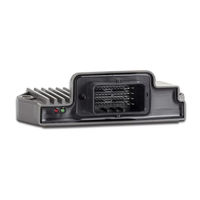
Jetter JXM-IO-E30 User Manual (70 pages)
Expansion module
Brand:
Jetter
| Category:
Computer Hardware
| Size: 8 MB
Table of Contents
Table of Contents
3
Typographical Conventions
6
Introduction
6
Information on this Document
6
Safety
7
General Information
7
Purpose
7
Intended Use
7
Usage Other than Intended
7
Warnings Used in this Document
7
Fig. 1 Design
9
Variants
9
Design
9
Product Description
9
Product Features
10
Diagnostic Capability Via Leds
10
Nameplate
11
Scope of Delivery
11
Fig. 2 Sample Nameplate
11
Fig. 3 Dimensions in MM
12
Dimensions
12
Technical Specifications
12
Mechanical Specifications
13
Electrical Properties
13
Tab. 1 Mechanical Specifications
13
Tab. 2 Output Driver Supply
13
Tab. 3 ECU Power Supply
13
Tab. 4 Ground Reference
13
Tab. 35 Parameter
13
Environmental Conditions
14
EMI Values
14
Tab. 5 Environmental Conditions
14
Tab. 6 Pulses ISO 7637-2
14
Tab. 7 Pulses ISO 16750-2
14
Tab. 8 Irradiation ISO 11452
14
Tab. 13 Impulse Voltages
15
Tab. 12 RF Induction
15
Tab. 11 Burst
15
Tab. 10 ESD en 61000-4-2
15
Tab. 9 Emission CISPR
15
Outputs
16
Tab. 14 Outputs Pwmi_H3_1
16
Tab. 15 Outputs PWM_H7_1
17
Tab. 16 Outputs DO_H3_1
17
Tab. 17 Sensor Output VEXT_SEN
18
Fig. 4 Graph: Principle of Linearization
18
Overcurrent Trip at Outputs
18
Current Diagnostics at the Outputs
18
Inputs
19
Tab. 19 Digital Inputs DI_P_1
20
Tab. 20 Configuration Inputs CFG1
20
Mechanical Installation
21
Requirements for Installation Location and Mounting Surface
22
Tab. 21 Requirements for the Mounting Surface
22
Fig. 5 Allowed Mounting Orientations
23
Allowed Mounting Orientations
23
Mounting Orientation
23
Forbidden Mounting Orientations
24
Fig. 6 Forbidden Mounting Orientation
24
Installing the Expansion Module
25
Fig. 7 Installation Drawing
25
Tab. 22 Fastening Material
25
Electrical Connection
26
Pin Assignment
28
MOLEX Connector
28
Fig. 8 MOLEX Connector - Pin Assignment
28
Tab. 23 Abbreviations Used in this Document
29
Tab. 24 MOLEX Mating Connector - Specification
29
Measures for Use in the Industrial Sector
30
Fig. 9 Block Diagram: Limiting Maximum Line Length
30
Fig. 10 Block Diagram: Overall Shielding
31
Device Information
32
Tab. 25 Device Information
32
Identification
32
Identification and Configuration
32
Electronic Data Sheet (EDS)
33
Operating System
33
Tab. 26 EDS Information
33
Tab. 27 Electronic Nameplate
33
Operating System Update of the Expansion Module
34
Tab. 28 Jeteasydownload Parameters
34
Tab. 18 Analog Inputs
36
Fig. 11 Concept and Control
36
Concept and Control
36
Parameterization
36
Configuration Options of Connections
36
I/O Ports and SDO Map
37
Tab. 29 Supported Ports and Interfaces - Overview
37
Tab. 30 SDO Mappings of the I/O Ports
37
Tab. 31 Subindexes for Accessing Parameters, Values, and Statuses
37
Overview - I/O Interfaces
38
Tab. 36 Status
39
Tab. 33 Input Values
40
Parameters, Values and Statuses
40
Tab. 32 Overview - I/O Interfaces
40
Tab. 34 Output Values
41
Setting the Node ID
45
Diagnostic Information
45
Tab. 37 Offset for Set Base Node ID
45
Tab. 38 Diagnostic Information
45
Tab. 42 System Parameters
45
Tab. 41 Resetting the Settings to Their Default Values
46
Tab. 39 Status Information
46
Tab. 40 Save Settings in EEPROM
46
Saving Settings Permanently and Resetting to Default Values
46
System Parameters
47
Mapping of Process Data Objects (Pdos)
48
RPDO Communication Parameters
48
Tab. 43 Validity of a PDO
48
Tab. 44 RPDO Communication Parameters
48
Tab. 46 RPDO Mapping Table
49
Mapping Tables
49
Tab. 45 TPDO Communication Parameters
49
TPDO Communication Parameters
49
Tab. 47 TPDO Mapping Table
50
Tab. 48 Mapping Entry U32
50
Tab. 49 Mapping of Digital Values
50
Tab. 50 SDO Commands, Activation of Byte-Wise Mapping
51
Sending Interface Input Values Via TPDO
52
Frequency Measurement at the Digital Inputs
54
Acquisition of Encoder Signals
54
Tab. 52 Input Values for ENCI_PNP
55
Tab. 51 Resolution of the Encoder Signals
55
NMT Commands
56
Troubleshooting
56
Tab. 53 Supported NMT Commands
56
Tab. 54 Byte Values of Emergency Objects
56
Tab. 55 Byte Values of the Error Memory
56
Tab. 56 Subindexes of the Error Memory
56
Tab. 57 Emergency Error Codes
57
Tab. 60 Heartbeat Monitoring - Example
58
Heartbeat
58
Tab. 59 Heartbeat Monitoring
58
Tab. 58 Index of the Heartbeat Message
58
Current Control with PID Controller
59
Test Scenario
59
Fig. 12 Comparison of Controller Types in a Control Loop
59
Tab. 61 General Conditions of the Test Scenario
59
Fig. 13: Test Scenario with the Control Parameters P = 100,000, I = 0, D = 0
60
Fig. 14: Test Scenario with the Control Parameters P = 100,000, I = 5,000, D = 0
60
Fig. 15 Test Scenario with the Control Parameters P = 100,000, I = 5,000, D = 400
61
Fig. 16 Test Scenario with the Control Parameters P = 100,000, I = 10,000, D = 400
61
Current Measurement at the Pwmi_H3_X Outputs
62
Dither Technology for Controlling Hydraulic Valves
62
Fig. 17 Dithering
62
Maintenance and Repairs
64
Maintenance, Repairs and Disposal
64
Storage and Shipment
64
Tab. 62 Accessories
66
List of Figures
67
Advertisement
Jetter JXM-IO-E30 User Manual (62 pages)
Expansion module
Brand:
Jetter
| Category:
Control Unit
| Size: 8 MB
Table of Contents
Table of Contents
3
1 Introduction
5
Information on this Document
5
Typographical Conventions
5
2 Safety
6
General Information
6
Purpose
6
Intended Use
6
Usage Other than Intended
6
Warnings Used in this Document
7
3 Product Description
8
Design
8
Features
8
Fig. 1 Design of the Device
8
Diagnostics Capabilities by Means of Status Indication
9
Nameplate
10
Scope of Delivery
10
Fig. 2 Sample Nameplate
10
4 Technical Specifications
11
Dimensions
11
Mechanical Specifications
11
Tab. 1 Mechanical Specifications
11
Fig. 3 Dimensions in MM
11
Electrical Properties
12
Environmental Conditions
12
Tab. 2 Power Supply of Output Drivers
12
Tab. 3 ECU Power Supply
12
Tab. 4 Connections to Ground
12
Tab. 5 Environmental Conditions
12
EMC Values
13
Tab. 6 Pulses to ISO 7637-2
13
Tab. 7 Pulses to ISO 16750-2
13
Tab. 8 Irradiation to ISO 11452
13
Tab. 9: Emission to CISPR 25
13
Tab. 10 ESD en 61000-4-2
13
Tab. 11 Burst
14
Tab. 12 RF Induction
14
Tab. 13 Impulse Voltages
14
Outputs
15
Tab. 14 Outputs Pwmi_H3_1
15
Tab. 15 Outputs PWM_H7_1
16
Tab. 16 Outputs DO_H3_1
16
Tab. 17 Sensor Output VEXT_SEN
16
Current Diagnostics at the Outputs
17
Overcurrent Shutdown at Outputs
17
Fig. 4 Graph: Principle of Linearization
17
Inputs
18
Tab. 18 Analog Inputs
18
Tab. 19 Digital Inputs DI_P_1
19
Tab. 20 Configuration Inputs CFG1_IN
19
5 Mechanical Installation
20
Mounting Orientation
21
Allowed Mounting Orientations
21
Fig. 5 Allowed Mounting Orientations
21
Prohibited Mounting Orientations
22
Minimum Requirements for the Installation Location
22
Tab. 21 Requirements for the Mounting Surface
22
Fig. 6 Prohibited Mounting Orientation
22
6 Electrical Connection
23
Connector Specification
24
MOLEX Connector - Pin Assignment
24
Tab. 22 Abbreviations Used in this Document
24
Fig. 7 MOLEX Connector - Pin Assignment
24
MOLEX Mating Connector - Specification
25
Tab. 23 MOLEX Mating Connector - Specification
25
Measures for Use in the Industrial Sector
26
Fig. 8: Schematic Diagram - Option 1
26
Fig. 9: Schematic Diagram - Option 2
27
7 Programming
28
Performing an os Update Via Jeteasydownload
28
Setting the Node ID
28
Concept and Control
29
Configuration Options of Connections
29
Tab. 24 Supported Ports and Interfaces - Overview
29
Fig. 10 Concept and Control
29
IO Ports and SDO Map
30
Tab. 25 SDO Mappings of the IO Ports
30
Tab. 26 Subindeces for Accessing Parameters, Values, and Statuses
30
Available Interfaces, Parameters, Values and Statuses
31
Tab. 27 Available Interfaces, Parameters, Values and Statuses
31
IO Interfaces
34
Tab. 29 IO Interface Output Values
35
Tab. 30 IO Interface Parameters
35
Tab. 31 Status of IO Interface
36
Device Information
38
Tab. 32 Device Information
38
Diagnostic Information
39
Tab. 33 Diagnostic Information
39
Tab. 34 EDS Information
39
Tab. 35 Electronic Nameplate
40
Tab. 36 Status Information
40
Saving Settings Permanently and Resetting to Default Values
41
Tab. 37 Save Settings in EEPROM
41
Tab. 38 Resetting the Settings to Their Default Values
41
System Parameters
42
Tab. 39 System Parameters
42
Mapping of Process Data Objects (Pdos)
43
RPDO Communication Parameters
43
TPDO Communication Parameters
43
Tab. 40 RPDO Communication Parameters
43
Tab. 41 TPDO Communication Parameters
43
Mapping Tables
44
Tab. 42 RPDO Mapping Table
44
Tab. 43 TPDO Mapping Table
44
Tab. 44 Mapping Entry U32
44
Mapping of Digital Values
45
Tab. 45 Mapping of Digital Values
45
Tab. 46 SDO Commands, Activation of Byte-Wise Mapping
45
STX Example: Output Value AI1 Voltage to TPDO1
46
Frequency Measurement at the Digital Inputs
47
Acquisition of Encoder Signals
48
Tab. 28 IO Interface Input Values
48
Tab. 47 Resolution of the Encoder Signals
48
Tab. 48 Available IO Interface Input Values for ENCI_PNP
48
Troubleshooting
49
Tab. 49 Byte Values of Emergency Objects
49
Tab. 50 Byte Values of the Error Memory
49
Tab. 51 Subindeces of the Error Memory
49
Tab. 52 Emergency Error Codes
49
Heartbeat
50
Tab. 53 Index of the Heartbeat Message
50
Current Control with PID Controller
51
Test Scenario
51
Tab. 54 Framework of the Test Scenario
51
Fig. 11 Comparison of Controller Types in a Control Loop
51
Fig. 12: Test Scenario with the Control Parameters P=10,000, I=0, D=0
52
Fig. 13: Test Scenario with the Control Parameters P=10,000, I=5,000, D=0
52
Fig. 14 Test Scenario with the Control Parameters P=10,000, I=5,000, D=400
53
Fig. 15 Test Scenario with the Control Parameters P=100,000, I=10,000, D=400
53
Current Measurement at the Pwmi_H3_X Outputs
54
Dither Technology for Controlling Hydraulic Valves
54
Fig. 16 Dither Technology
54
8 Maintenance and Repairs
56
Maintenance, Repairs and Disposal
56
Storage and Shipment
56
9 Service
57
Customer Service
57
10 Spare Parts and Accessories
58
Accessories
58
Tab. 55 Accessories
58
List of Tables
59
Jetter JXM-IO-E30 Installation Manual (35 pages)
Brand:
Jetter
| Category:
Computer Hardware
| Size: 0 MB
Table of Contents
Technische Daten
8
Product Description
23
Technical Specifications
26
Mechanical Installation
28
Electrical Connection
31
Advertisement
Advertisement
Related Products
Jetter JXM-IO-EW30
Jetter JXM-IO-E32
Jetter JX3-THI2-RTD-EI
Jetter JVM-407B-HMI
Jetter JXM-IO-E31
Jetter JXM-IO-E31-G20-K00
Jetter JXM-IO-E31-G20-K00-O01
Jetter JXM-IO-EX30
Jetter JXM-IO-EW30-G27
Jetter JXM-HMI
Jetter Categories
Control Unit
Controller
Amplifier
Computer Hardware
Recording Equipment
More Jetter Manuals
Login
Sign In
OR
Sign in with Facebook
Sign in with Google
Upload manual
Upload from disk
Upload from URL