Table of Contents
Advertisement
Quick Links
Advertisement
Chapters
Table of Contents

Subscribe to Our Youtube Channel
Related Manuals for Jetter JXM-IO-E30


Summary of Contents for Jetter JXM-IO-E30
- Page 1 User Manual JXM-IO-E30 Expansion module 60883467_03 We automate your success.
- Page 2 This document has been compiled by Jetter AG with due diligence based on the state of the art as known to them. Any revisions and technical advancements of our products are not automatically made available in a revised document. Jetter AG shall not be liable for any errors either in form or content, or for any missing updates, as well as for any damage or detriment resulting from such failure.
-
Page 3: Table Of Contents
Inputs............................ 19 5 Mechanical installation ........................ 21 Requirements for installation location and mounting surface ............ 22 Mounting orientation ........................ 23 5.2.1 Allowed mounting orientations.................. 23 5.2.2 Forbidden mounting orientations ................... 24 Installing the expansion module .................... 25 User Manual – JXM-IO-E30... - Page 4 8.11.1 Test scenario ......................... 59 8.11.2 Current measurement at the PWMi_H3_X outputs ............ 62 8.12 Dither technology for controlling hydraulic valves .............. 62 9 Maintenance and repairs........................ 64 Maintenance, repairs and disposal.................... 64 Storage and shipment ....................... 64 User Manual – JXM-IO-E30...
- Page 5 Jetter AG Table of Contents 10 Service ............................... 65 10.1 Customer service........................ 65 11 Spare parts and accessories ...................... 66 11.1 Accessories .......................... 66 User Manual – JXM-IO-E30...
-
Page 6: Introduction
For information on new revisions of this document, visit the download area on our website. This document is not subject to any updating service. Start | Jetter - We automate your success. For further information refer to the following information products: ■... -
Page 7: Safety
Indicates an imminently hazardous situation which, if not avoided, will result in death or serious injury. WARNING Medium risk Indicates a potentially hazardous situation which, if not avoided, could result in death or serious injury. User Manual – JXM-IO-E30 7 / 70... - Page 8 Indicates a hazardous situation which, if not avoided, could result in minor or moderate injury. NOTICE Material damage Indicates a situation which, if not avoided, could result in mal- functions or material damage. User Manual – JXM-IO-E30 8 / 70...
-
Page 9: Product Description
Jetter AG Product Description | 3 3 Product Description The JXM-IO-E30 expansion module is a cost-effective and universally applicable I/O extension for self-propelled machines. For use in the industrial sector, addi- tional requirements must be met: ■ Measures for use in the industrial sector [} 30] 3.1 Variants... -
Page 10: Product Features
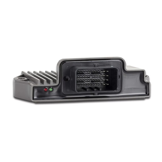
■ Separate connections for logic and output driver supply ■ Total current output of up to 25 A 3.4 Diagnostic capability via LEDs The JXM-IO-E30 is equipped with 2 LEDs to indicate various states and errors. Color Blinking pattern Description ■ Operating voltage is present (VBAT_ECU). -
Page 11: Nameplate
Certification mark Registration number and hardware revision Barcode Serial number Model code number 3.6 Scope of delivery Scope of delivery Item number Quantity JXM-IO-E30-G20-K00 10001687 JXM-IO-E30-G20-K00-O01 10002046 Model with CAN IN/OUT and AI10V User Manual – JXM-IO-E30 11 / 70... -
Page 12: Technical Specifications
Jetter AG Technical specifications | 4 4 Technical specifications This chapter contains information on electrical and mechanical data as well as operating data of the JXM-IO-E30. 4.1 Dimensions 43.1 38.4 18.6 93.5 Fig. 3: Dimensions in mm INFO CAD data CAD data of the device can be found in the download area of our homepage. -
Page 13: Mechanical Specifications
49 mA + total current at VEXT_SEN At 24 V approx. 34 mA + total current at VEXT_SEN Tab. 3: ECU power supply Ground reference Purpose GND_PWR Ground for VBAT_PWR and VBAT_ECU GND_SEN Ground for VEXT_SEN Tab. 4: Ground reference User Manual – JXM-IO-E30 13 / 70... -
Page 14: Environmental Conditions
Load dump 70 V / 2 Ω / 350 ms Tab. 7: Pulses ISO 16750-2 Irradiation Parameter Values Functional class ISO 11452 Protection against RF 20 MHz ... 2 GHz noise 60 V/m 20 MHz ... 2 GHz 75 V/m 20 MHz ... 57 MHz and 82 MHz ... 2 GHz 100 V/m Tab. 8: Irradiation ISO 11452 User Manual – JXM-IO-E30 14 / 70... -
Page 15: Tab. 9 Emission Cispr
EN 61000-6-1 Tab. 11: Burst RF induction Parameter Values Criterion Standards RF induction 10 V EN 61000-6-2 3 V EN 61000-6-1 Tab. 12: RF induction Impulse voltages Parameter Values Criterion Standards Impulse voltages ±1 kV EN 61000-6-2 ±0.5 kV EN 61000-6-1 Tab. 13: Impulse voltages User Manual – JXM-IO-E30 15 / 70... -
Page 16: Outputs
Load range 0.2 A ... 7 A per channel Properties No-load detection Compatible with inductive load Overcurrent detection Current diagnostics Diagnostics value Measuring accuracy Related to the measuring < 0.2 A ±45 % range 7 A ≤ 1.5 A ±35 % > 1.5 A ... 7 A ±25 % User Manual – JXM-IO-E30 16 / 70... -
Page 17: Tab. 15 Outputs Pwm_H7_1
Use as input NPN and PNP input Switching the interface to NPN or PNP affects the entire DO_H3_x group! L level ≤ 1.6 V H level ≥ 4.6 V Input resistance PNP 94 kΩ NPN 10 kΩ Tab. 16: Outputs DO_H3_1 ... DO_H3_4 User Manual – JXM-IO-E30 17 / 70... -
Page 18: Current Diagnostics At The Outputs
OVERCURRENT_TIME. If an overcurrent event is detected, the output shuts down and the overcurrent bit is set for 10 seconds. During this time the port can- not be switched on again. ü Re-enabling the The JXM-IO-E30 is in the Operational state. port ü... -
Page 19: Inputs
4.7 Inputs Within the operating voltage range, all inputs are voltage-proof and overcurrent protected. The JXM-IO-E30 has 3 separate VEXT_SEN connector pins which should be used to supply the sensors. The connector pins output the battery volt- age via a PTC thermistor. The output voltage can be read back in the device so that a failure of the sensor supply can be detected. -
Page 20: Tab. 19 Digital Inputs Di_P_1
VBAT_ECU or GND via an offset. Parameter Description Configuration inputs for configuring the node ID Abbreviation CFG1 CFG2 Quantity Tab. 20: Configuration inputs CFG1 … CFG2 For more information refer to chapter Setting the node ID [} 45]. User Manual – JXM-IO-E30 20 / 70... -
Page 21: Mechanical Installation
Functional impairment due to magnets or motors with coil Using magnets or motors with a coil in the vicinity of the JXM-IO-E30 may adversely affect current readings of the in- puts and outputs. ► Ensure that there is sufficient clearance or shield the JXM-IO-E30. -
Page 22: Requirements For Installation Location And Mounting Surface
Requirements for ■ Sufficient air circulation the installation ■ Sufficient space between the device and parts that may become very hot space ■ The device must be accessible for service work at all times. User Manual – JXM-IO-E30 22 / 70... -
Page 23: Mounting Orientation
INFO Overheating due to incorrect mounting orientation If the device switches itself off, check whether the device has overheated due to an unfavorable mounting orientation. 5.2.1 Allowed mounting orientations Fig. 5: Allowed mounting orientations User Manual – JXM-IO-E30 23 / 70... -
Page 24: Forbidden Mounting Orientations
Do not route the connector plug vertically upwards. ► Do not use a steam jet near the unprotected device. Any orientation where the connector plug is not protected against splash water or condensation is prohibited. Fig. 6: Forbidden mounting orientation User Manual – JXM-IO-E30 24 / 70... -
Page 25: Installing The Expansion Module
Material Type Quantity Screws/bolts Washers DIN 125-1 Tab. 22: Fastening material Mechanical ► Use both mounting lugs to fasten the JXM-IO-E30. The stud torque is 4 Nm installation max. Fig. 7: Installation drawing User Manual – JXM-IO-E30 25 / 70... -
Page 26: Electrical Connection
Surges may cause malfunctions or damage to the product. ► Protect the voltage inputs from surges according to the re- quirements. ► Ensure that the device is handled in accordance with ESD regulations. User Manual – JXM-IO-E30 26 / 70... - Page 27 Electrical connection | 6 NOTICE Interferences due to differences in potential Differences in potential can lead to interferences. ► Wire sensors and actuators including their supply lines in star configuration to prevent differences in potential. User Manual – JXM-IO-E30 27 / 70...
-
Page 28: Pin Assignment
Configuration pin for setting the CAN ID DI_P Digital and frequency input DI_P_1 Digital and frequency input which can also be used as NPN input as of HW Rev. 02.00. DO_H3 Digital high-side output User Manual – JXM-IO-E30 28 / 70... -
Page 29: Tab. 23 Abbreviations Used In This Document
Manufacturer part number 0643201311 Crimp contacts For 0.75 mm² lines Quantity Manufacturer part number 0643221029 For 1.5 mm² lines Quantity Manufacturer part number 0643231039 Protective cap Manufacturer part number 0643201301 Tab. 24: MOLEX mating connector - Specification User Manual – JXM-IO-E30 29 / 70... -
Page 30: Measures For Use In The Industrial Sector
Electrical connection | 6 6.2 Measures for use in the industrial sector The JXM-IO-E30 was developed for the automotive sector. In order to be able to use the device also in the industrial sector in conformity with CE, you must imple- ment the measures of one of the following options: Option 1 - Limitation of the maximum cable length to 3 m... -
Page 31: Fig. 10 Block Diagram: Overall Shielding
Use a transil diode of type BZW06-33 at each DI_P input and at the outputs PWM_H7, PWMi_H3 and DO_H3. DI_P digital inputs Overall shielding JXM-IO-E30 Controller AI analog inputs Control cabinet housing Control cabinet housing Other lines PWM_H7 PWMi_H3 DO_H3 Fig. 10: Block diagram: Overall shielding User Manual – JXM-IO-E30 31 / 70... -
Page 32: Identification And Configuration
Jetter AG Identification and Configuration | 7 7 Identification and Configuration 7.1 Identification This chapter describes how to identify the JXM-IO-E30 device: ■ Determining the hardware revision ■ Retrieving Electronic Data Sheet (EDS) information. The EDS holds numerous non-volatile production-relevant data. -
Page 33: Electronic Data Sheet (Eds)
Jetter AG Identification and Configuration | 7 7.1.2 Electronic Data Sheet (EDS) Each JXM-IO-E30 features an Electronic Data Sheet (EDS). Production-specific data is stored in the CANopen object indexes 0x4555 and 0x4565. EDS information Types of Index Subindex Description Type... -
Page 34: Operating System Update Of The Expansion Module
Identification and Configuration | 7 7.2.1 Operating System Update of the Expansion Module This chapter describes how to carry out an operating system update on the JXM-IO-E30 expansion module. You have got several options to transfer the OS file to the expansion module: ■... - Page 35 The device starts in boot loader mode with a single heartbeat in init state (data = 0x00). Wait for approx. 7 seconds while the device formats the flash memory. ð The device starts the download process. ð The device starts automatically with the new firmware. User Manual – JXM-IO-E30 35 / 70...
-
Page 36: Parameterization
8.1 Concept and control The concept of the JXM-IO-E30 is based on the assignment of interfaces to the inputs and out- puts of the device. Each input and output of the device is called a port and can be configured. -
Page 37: I/O Ports And Sdo Map
A previously set value is not retained when changing from the Operational Pre-Operational state. Only possible in the Operational state, otherwise an error occurs (SDO abort). 50 … 199 Parameter Tab. 31: Subindexes for accessing parameters, values, and statuses User Manual – JXM-IO-E30 37 / 70... -
Page 38: Overview - I/O Interfaces
FI_PNP SENSOR_SUPPLY I_FREQUENCY INACTIVE Frequency input TIMEOUT_TIME I_DUTY_CYCLE ERROR GATE_TIME I_DIGITAL SUPPLY_FAULT (active-high with I_COUNTER TIMEOUT pull-down) I_PERIODIC_ TIME I_H_PULSE_TIME I_L_PULSE_TIME DI_NPN SENSOR_SUPPLY I_DIGITAL INACTIVE Digital input I_COUNTER ERROR (active-low with SUPPLY_FAULT pull-up) User Manual – JXM-IO-E30 38 / 70... -
Page 39: Tab. 36 Status
Reserved 10/a CPWMO_HS3 PWM_FRQ I_HCURRENT INACTIVE High-side output DITHER_FRQ O_HCURRENT ERROR DITHER_AMP OVERCURRENT (up to 3 A; with CURRENT_CONTROL_P OPEN_CIRCUIT current control) CURRENT_CONTROL_I CC_UNLOCK CURRENT_CONTROL_D MAX_CURRENT OVERCURRENT_TIME CURRENT_CONTROL_ TIME FILTER_DEEP MIN_DEVIATION MIN_CURRENT OPENCIRCUIT_ DETECTION User Manual – JXM-IO-E30 39 / 70... -
Page 40: Parameters, Values And Statuses
Subindex Description Type access Value range I_VOLTAGE Voltage value 1 mV I_RATIO Relation to VBAT_ECU 1 ‰ I_CURRENT Current value (small measuring 1 µA range) I_HCURRENT Current value (large measuring 1 mA range) I_FREQUENCY Frequency value 0.1 Hz User Manual – JXM-IO-E30 40 / 70... -
Page 41: Tab. 34 Output Values
Associated sensor supply, 0 = OFF which is also monitored. VEXT_SEN_1 VEXT_SEN_2 VEXT_SEN_3 Default: 0 PWM_FRQ PWM frequency 0.1 Hz Default: 1 kHz DITHER_FRQ Dither frequency 0.1 Hz Default: 1000 DITHER_AMP Dither amplitude 0.1 % Default: 0 User Manual – JXM-IO-E30 41 / 70... - Page 42 1 … 32 tion depth Default: 1 GATE_TIME Measuring time of the fre- 1 ms quency measurement Default: 1000 MIN_DEVIATION Minimum deviation for in- µA or mV put values (as of OS Default for AI: 2.04.0.00) User Manual – JXM-IO-E30 42 / 70...
- Page 43 PWM outputs and cur- Default: 1 rent-controlled outputs. This may lead false cable break errors. RESOLUTION Resolution, e.g. at encoder 0 … 2 input 1/4 resolution 1/2 resolution Full resolution Default: 0 Tab. 35: Parameter User Manual – JXM-IO-E30 43 / 70...
- Page 44 This status entry is only checked while the de- vice is booting! 0x00000100 TIMEOUT The time for frequency measurement has been ex- ceeded. 0x00000200 CC_UNLOCK The current control is not within the control range. Tab. 36: Status User Manual – JXM-IO-E30 44 / 70...
-
Page 45: Setting The Node Id
Description Type Unit access 0x2000 Number of supported entries VBAT_PWR 7V IO PCB temperature 0.1 °C CPU temperature 0.1 °C CPU VRef SPWR1 SPWR2 SPWR3 VBAT_ECU CFG1 CFG2 Total current ±50 % Tab. 38: Diagnostic information User Manual – JXM-IO-E30 45 / 70... -
Page 46: Saving Settings Permanently And Resetting To Default Values
Tab. 41: Resetting the settings to their default values INFO Loading the settings from the EEPROM During bootup, the last saved settings are automatically loaded. During a firmware update, the settings may be reset to the default values. User Manual – JXM-IO-E30 46 / 70... -
Page 47: System Parameters
3. The vehicle controller reads the CRC via index 0x4556, subindex 1 and saves this value locally in a remanent memory. 4. After restarting the JXM-IO-E30, the vehicle controller compares the locally saved CRC value with the value in index 0x4556, subindex 1. If the values do not match, parameteri- zation must be restarted. -
Page 48: Mapping Of Process Data Objects (Pdos)
Event Time U16 R/W 1 ms 500 (500 ms) Tab. 44: RPDO communication parameters INFO Write access to communication parameters Write access to communication parameters is only possible if the JXM-IO-E30 is in the Pre-Operational state. User Manual – JXM-IO-E30 48 / 70... -
Page 49: Tpdo Communication Parameters
500 (500 ms) Tab. 45: TPDO communication parameters INFO Write access to communication parameters Write access to communication parameters is only possible if the JXM-IO-E30 is in the Pre-Operational state. For a configuration example, refer to chapter Sending interface input values via TPDO [} 52]. -
Page 50: Tab. 47 Tpdo Mapping Table
The SDO shows the value I_DIGITAL for selected values. If you have not previously configured the corresponding port for digital values, then no error message is issued and the value in this bit is not defined. User Manual – JXM-IO-E30 50 / 70... -
Page 51: Tab. 50 Sdo Commands, Activation Of Byte-Wise Mapping
To switch from the default bitwise mapping to the bytewise mapping after system startup, 2 SDO commands must be sent to the node: Index Subindex Description Data length Value 0x2001 Enabling byte-wise mapping 4 bytes 0xb4c0ffee 4 bytes Tab. 50: SDO commands, activation of byte-wise mapping User Manual – JXM-IO-E30 51 / 70... -
Page 52: Sending Interface Input Values Via Tpdo
Jetter AG Parameterization | 8 8.6.5 Sending interface input values via TPDO To send interface input values via TPDO, proceed as follows: Switch the JXM-IO-E30 to Pre-Operational state. Assign the desired interface. Invalidate the TxPDO object. Disable the mapping. Enter the mapping value. - Page 53 //Validating object, setting uppermost bit to 0, specifying PDO COB dTemp := 0x180+0x30; CanOpenDownloadSDO( cCanChannel, cJXMNodeId, 0x1800, 1, CANOPEN_DWORD, 4, dTemp, iBusy); when SDOACCESS_FINISHED(iBusy) continue; //Switch JXM-IO-E30 to Operational state CanOpenSetCommand( cCanChannel,CAN_CMD_NMT,CAN_CMD_NMT_Value( cJXMNodeId,CAN_NMT_OPERATIONAL)); User Manual – JXM-IO-E30 53 / 70...
-
Page 54: Frequency Measurement At The Digital Inputs
If, for example, you configure input DI_P_3 as ENCI_PNP, the adjacent in- put DI_P_4 is automatically configured as ENCI_PNP. If you reconfigure one of the two inputs, the adjacent input automatically becomes INACTIVE - no encoder signals are acquired any more. User Manual – JXM-IO-E30 54 / 70... -
Page 55: Tab. 51 Resolution Of The Encoder Signals
You can query the following Input values: Input value Description PDO send condition I_COUNTER 32-bit counter running forward Event Time and backward I_DIRECTION Current direction In case of change Tab. 52: Input values for ENCI_PNP User Manual – JXM-IO-E30 55 / 70... -
Page 56: Nmt Commands
Operational state START Starts the JXM-IO-E30 STOP Stops the JXM-IO-E30, the JXM-IO-E30 continues to send heart- beat signals and process NMT commands. Tab. 53: Supported NMT commands 8.10 Troubleshooting Emergency object telegrams (EMCY telegrams) EMCY telegrams are sent at startup or after any changes at an inhibit time of 50 ms. -
Page 57: Tab. 57 Emergency Error Codes
Processing errors due to incorrect length of PDOs 0x8220 PDO length exceeded 0xff00 Configuration error on the device 0xff01 I/O-Port OVERVOLTAGE 0xff02 I/O-Port OVERCURRENT 0xff03 I/O-Port SUPPLYFAULT 0xff05 I/O-Port OPEN_CIRCUIT 0xff06 I/O-Port TIMEOUT 0xff07 I/O-Port CC_UNLOCK Tab. 57: Emergency Error Codes User Manual – JXM-IO-E30 57 / 70... -
Page 58: Heartbeat
■ = 4 bytes (U32) ■ = reserved ■ = 127 (node ID) ■ = 1000 (timeout in ms) Read first configuration in first entry. r 0x1016 1 Tab. 60: Heartbeat Monitoring - Example User Manual – JXM-IO-E30 58 / 70... -
Page 59: Current Control With Pid Controller
The individual P, I and D controllers usually have the following characteristics: Fig. 12: Comparison of controller types in a control loop Step response Time 8.11.1 Test scenario The PID controller was tested on the JXM-IO-E30 under the following conditions: Condition Description Output 1 kHz PWM Control period 10 ms... -
Page 60: Fig. 13: Test Scenario With The Control Parameters P = 100,000, I = 0, D = 0
Closed-loop control parameters: P = 100,000, I = 5,000, D = 0, Measurements: blue = setpoint, red = actual value Fig. 14: Test scenario with the control parameters P = 100,000, I = 5,000, D = 0 The I controller also works satisfactorily, the setpoint is reached with this setting. User Manual – JXM-IO-E30 60 / 70... -
Page 61: Fig. 15 Test Scenario With The Control Parameters P = 100,000, I = 5,000, D = 400
In this example, the period of the setpoint signal was selected with approx. 10 ms for illustrative purposes. For fast control, the P value should be increased and the sampling time reduced to 5 ms. Settling times < 50 ms can be achieved. User Manual – JXM-IO-E30 61 / 70... -
Page 62: Current Measurement At The Pwmi_H3_X Outputs
If the valve can only be controlled at higher frequencies (1 kHz), the PWM signal can be modu- lated. This is known as dithering and also prevents the needle from coming to rest. You can set the frequency and amplitude of the dither signal in the JXM-IO-E30: ■... - Page 63 ■ Decrease the amplitude of the dither signal. ■ Use the averaging filter on the current feedback of the output. ■ Adjust the PID parameters. User Manual – JXM-IO-E30 63 / 70...
-
Page 64: Maintenance And Repairs
In case of damaged packaging inspect the device for any visible damage, and in- form your freight forwarder and the Jetter AG of the damage caused during ship- ment. If the device is damaged or has been dropped, it is strictly forbidden to use User Manual –... - Page 65 To contact them, please call our technical hotline or use the contact form on our homepage: Technical hotline | Jetter - We automate your success. You are also welcome to send an e-mail to our technical hotline: hotline@jetter.de...
-
Page 66: Tab. 62 Accessories
Only use accessories recommended by Jetter AG. 11.1 Accessories INFO Ordering accessories The accessories are not part of the scope of delivery. Suitable accessories can be obtained from Jetter AG. Accessories Item number Cable harness of 3 m length with open end, 60882322_01 incl. - Page 67 Fig. 14 Test scenario with the control parameters P = 100,000, I = 5,000, D = 0 ....... Fig. 15 Test scenario with the control parameters P = 100,000, I = 5,000, D = 400 ......Fig. 16 Test scenario with the control parameters P = 100,000, I = 10,000, D = 400 ......Fig. 17 Dithering ..........................User Manual – JXM-IO-E30 67 / 70...
- Page 68 Tab. 33 Input values ..........................Tab. 34 Output values .......................... Tab. 35 Parameter..........................Tab. 36 Status ............................Tab. 37 Offset for set base node ID...................... Tab. 38 Diagnostic information ......................Tab. 39 Status information........................User Manual – JXM-IO-E30 68 / 70...
- Page 69 Tab. 57 Emergency Error Codes ......................Tab. 58 Index of the heartbeat message ....................Tab. 59 Heartbeat monitoring ....................... Tab. 60 Heartbeat Monitoring - Example....................Tab. 61 General conditions of the test scenario ................... Tab. 62 Accessories ..........................User Manual – JXM-IO-E30 69 / 70...
- Page 70 Jetter AG Graeterstrasse 2 71642 Ludwigsburg www.jetter.de E-mail info@jetter.de Phone +49 7141 2550-0 We automate your success.
Need help?
Do you have a question about the JXM-IO-E30 and is the answer not in the manual?
Questions and answers