Sign In
Upload
Manuals
Brands
JCM Manuals
Banknote Counter
ivizion sh
JCM ivizion sh Manuals
Manuals and User Guides for JCM ivizion sh. We have
1
JCM ivizion sh manual available for free PDF download: Operation And Maintenance
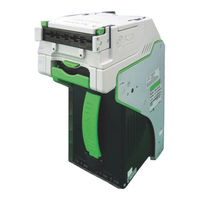
JCM ivizion sh Operation And Maintenance (158 pages)
ivizion series next-generation banknote acceptor unit
Brand:
JCM
| Category:
Banknote Counter
| Size: 10 MB
Table of Contents
Table of Contents
3
1 General Information
17
Ivizion Units
17
Ivizion® Series
17
Next-Generation Banknote Acceptor Unit
17
Product Descriptions
18
Model Descriptions
18
Type Descriptions
18
Software Descriptions
18
Precautions
18
User Cautions
18
Installation Cautions
18
Table 1-1 Ivizion Model Number Specifications
18
Table 1-2 Ivizion Type Number Specifications
18
Table 1-3 Ivizion Software Number Specifications
18
Mounting, Dismounting & Transportation
19
Placing Foreign Objects into the Unit
19
Preventive Maintenance
19
Banknote Fitness Requirements
19
Reference Paper Use Precautions
20
Primary Features
20
Component Names
21
Specifications
22
Ivizion SS/SH Specification
22
Table 1-4 Ivizion Technical Specifications
22
Technical Specifications
22
Electrical Specifications
23
Environmental Specifications
23
Structural Specifications
23
RFID Specifications
23
Table 1-5 Ivizion Environmental Specifications
23
Table 1-6 Ivizion Electrical Specifications
23
Table 1-7 Ivizion Structural Specifications
23
Table 1-8 RFID Specifications
23
Ivizion LD Specification
24
Environmental Specifications
24
Table 1-10 Ivizion LD Environmental Specifications
24
Table 1-9 Ivizion LD Technical Specifications
24
Technical Specifications
24
Electrical Specifications
25
Structural Specifications
25
Table 1-11 Ivizion LD Electrical Specifications
25
Table 1-12 Ivizion LD Structural Specifications
25
Unit Dimensions
26
Ivizion SS Unit Outside Dimensions
26
Figure 1-8 Ivizion SS Unit with Standard Cash Box/Metal Bezel Outside Dimensions
27
Ivizion SS Unit Installation/Maintenance Space Requirements
28
Ivizion SH Entire Unit Outside Dimensions
29
Ivizion SH Unit Installation/Maintenance Space Requirements
30
Ivizion Cash Box Outside Dimensions
31
Large Cash Box Outside Dimensions
31
Standard Cash Box Outside Dimensions
31
HC Cash Box Outside Dimensions
32
Technical Contact Information
33
Americas
33
JCM American
33
Europe, Middle East, Africa & Russia
33
JCM Europe Gmbh
33
UK & Ireland
33
JCM Europe (UK Office)
33
Asia and Oceania
33
Japan Cash Machine Co., Ltd. (Hq)
33
JCM Gold (HK) Ltd
33
2 Installation
35
Installation Procedure
35
Lock Installation
36
Unlock Procedure
36
DIP Switch Configurations
37
Primary LED Indications
37
Table 2-1 Denomination INHIBIT DIP Switch Settings
37
Table 2-2 JCM Private Line DIP Switch Setting
37
Table 2-3 Software DIP Switch Settings
37
Table 2-4 Serial Communication DIP Switch Settings
37
Table 2-5 LED Error Pattern Indications
37
Connector Pin Assignments
38
Table 2-6 Ivizion SS/LD USB Connection Pin Assignments
38
Connector Pin Assignments (Continued 1)
39
Table 2-7 Ivizion SS/LD Photo-Coupler Connector Pin Assignments
39
Connector Pin Assignments (Continued 2)
40
Table 2-8 Ivizion SS/LD RS232C Connector Pin Assignments
40
Connector Pin Assignments (Continued 3)
41
Table 2-9 Ivizion SS/LD Cctalk Connector Pin Assignments
41
Connector Pin Assignments (Continued 4)
42
Table 2-10 Ivizion SS/LD TTL Connector Pin Assignments
42
Connector Pin Assignments (Continued 5)
43
Table 2-11 Ivizion SS/LD Bezel JPL (CN7) Connection Pin Assignments
43
Preventive Maintenance
44
Retrieving Banknotes
44
Clearing a Banknote Jam
44
Cleaning Procedure
44
Sensor Cleaning Procedure
44
Ivizion Optional LD Version Unit Installation
45
Ivizion Sensor Locations
46
Table 2-12 Ivizion Sensor Cleaning Location Types
46
Standard Interface Circuit Schematics
47
Interface Circuit Schematics (Continued 1)
48
Interface Circuit Schematics (Continued 2)
49
Interface Circuit Schematics (Continued 3)
50
Operational Flowcharts
51
Operational Flowchart (Continued 1)
52
Operational Flowchart (Continued 2)
53
Figure 2-21 Ivizion LD Banknote Acceptor Operational Flowchart (Part 2 - Validating)
53
3 Communications
55
Americas
55
JCM American
55
Europe, Middle East, Africa & Russia
55
JCM Europe Gmbh
55
UK & Ireland
55
JCM Europe (UK Office)
55
Asia and Oceania
55
JCM Gold (HK) Ltd
55
Japan Cash Machine Co., Ltd. (Hq)
55
Tool Requirements
57
Pusher Unit Timing Belt Removal
57
Ivizion Standard and Large Cash Box
57
Figure 4-1 Pusher Mechanism Screws Removal
57
Figure 4-2 Pusher Mechanism Removal
57
Figure 4-3 Pusher Mechanism Cover Removal
58
Figure 4-4 Stacker Guide Removal
58
Figure 4-5 Stacker Guide Reassembly
58
Figure 4-6 Right Frame Outer "R" Removal
58
Ivizion HC Cash Box
59
Figure 4-7 Left Frame Outer "L" Removal
59
Figure 4-8 Timing Belt Removal
59
Figure 4-9 Pusher Mechanism Removal
59
Figure 4-10 HC Box Stacker Base Removal
59
Figure 4-11 Pusher Guide Removal
60
Figure 4-12 Stacker Guide Removal
60
Figure 4-13 Stacker Guide Reassembly
60
Figure 4-14 Outer Guide R Removal 1
60
Figure 4-15 Outer Guide R Removal 2
60
Figure 4-16 Outer Guide L Removal 1
61
Figure 4-17 Outer Guide L Removal 2
61
Figure 4-18 Timing Belt Removal
61
Figure 4-19 TR Bottom Cover Removal
61
Figure 4-20 TR Side Cover "A" Removal
61
Home Position Sensor Board/Home Position Sensor, FFC & Interface Connector Board Removals
61
4 Disassembly/Reassembly
57
Board Removals
62
RFID Module & Harness Removals
62
Validation CPU & Controller CPU Board Removals
62
Figure 4-21 Home Position Sensor Board, Home Position Sensor FFC Assembly and Interface Connector Board Removals
62
Figure 4-22 RFID Module & Harness Removal
62
Figure 4-23 CPU Board Module Removal
62
Figure 4-24 Extension Memory Board Removal
62
USB FPC, Power FPC & Interface FPC Cable Removals
63
Figure 4-25 Validation CPU Board and Control CPU Board Removal
63
Figure 4-26 Motor Module Removal
63
Figure 4-27 USB FPC, Power FPC & Interface FPC Cable Removal
63
Validation Unit Harness Removal
64
Interrupter Board Removal
64
Motor Unit Timing Belt Removal
64
Figure 4-28 Validation Unit Harness Removal
64
Figure 4-29 Interrupter Board Removal
64
Figure 4-30 Timing Belt Removal
64
Figure 4-31 Timing Belt Reassembly Path
64
Stacker Motor & Transport Motor Removals
65
Bezel Hold Clips a & B Removal
65
Sensor Transfer Board/Cis Ffc/Transmissive Light FFC & Upper UV FPC Sensor Removals
65
Figure 4-32 Stacker & Transport Motor Removal
65
Figure 4-33 Bezel Hold Chips A&B Removal
65
Figure 4-34 Upper Cover Removal
65
Figure 4-35 Sensor Transfer Board Assembly, CIS FFC, Transmissive Light & Upper UV FPC Cable Removal
65
Validation Sensor Board Assembly Removal
66
Validation Sensor FPC Cable Removal
66
Figure 4-36 Ivizion Head Cover a Removal
66
Figure 4-37 Validation Sensor Board Assembly Removal
66
Figure 4-38 Validation Sensor FPC Removal
66
Figure 4-39 Validation Sensor FPC Reassembly
66
Cis/Transmissive Light & Upper UV Sensor Removals
67
Figure 4-40 Upper Validation Part Removal
67
Figure 4-41 Ivizion Head BG85B Removal
67
CIS/CIS Fpc/Lower UV Sensor & Lower UV FFC Removal
68
Figure 4-42 CIS, Transmissive Light & Upper UV Sensor Removal
68
Figure 4-43 Ivizion BG 85A HEAD Removal
68
Figure 4-44 Lower Validation Part Removal
69
Figure 4-45 CIS, CIS FPC, Lower UV Sensor & Lower UV FFC Removal
69
Validation Unit Timing Belt Removal
70
Reassembly Cautions
70
Figure 4-46 Timing Belt Removal
70
Figure 4-47 Timing Belt Replacement
70
Figure 4-48 Upper/Lower UV Sensors Location
70
5 Wiring Diagrams
71
Ivizion System Wiring Diagram
71
Figure 5-1 Ivizion System Wiring Diagram
71
6 Calibration and Testing
73
Tool Requirements
73
Installation Procedures
73
Application Software Installation
73
Figure 6-1 Tools and Connections
73
Figure 6-2 USB Cable Type Requirements
73
Figure 6-3 Setup.exe File Location
73
Figure 6-4 Installshield Wizard Screen
73
Driver Installation Procedure
74
Figure 6-5 Destination Folder Screen
74
Figure 6-6 Current Settings Confirmation
74
Figure 6-7 Installation Completion Screen
74
JCM Tool Suite Standard Edition Mode
75
Download Procedures
75
Download the Upgrade Program
75
Figure 6-10 Normal Mode Selection
75
Figure 6-11 Test Mode Selection
75
Figure 6-12 DIP Switches All off
75
Figure 6-13 JCM Tool Suite Standard Edition Screen
75
Figure 6-14 JCM Tool Suite Standard Edition Screen Pull-Down Menu
75
Downloading the Program First Time
76
Figure 6-15 Browse Screen Button Location
76
Figure 6-16 Ivizion Software Program Selection
76
Figure 6-19 DIP Switches 6, 7, & 8 on
76
Figure 6-20 JCM Tool Suite Standard Edition Screen 2
77
Calibration
78
When to Calibrate
78
Calibration Order
78
Calibration Tool Requirements
78
Reference Paper Placement
78
Figure 6-26 Remote Calibration Tools Required
78
Figure 6-27 KS-072/KS-089 Reference Paper
78
Placing the KS-072/KS-089 Reference Paper
78
Table 6-1 Ivizion Sensor Calibration Order
78
Calibration Only
79
Calibration Procedure
79
Figure 6-29 Reference Paper Setting 2
79
Figure 6-30 DIP Switch #8 on
79
Figure 6-32 Ivizion Calibration Ver.X.XX Screen
79
Figure 6-33 Feed-Out Calibration Proceeding Screen
80
Figure 6-34 Calibration Information Screen 1
80
Figure 6-36 Pusher Plate Release Location
80
Figure 6-37 Cardboard Setting Location
80
Figure 6-38 Exit Calibration Proceeding Screen
80
Figure 6-40 UV Calibration Proceeding Screen
81
Figure 6-43 CIS Calibration Proceeding Screen
81
Figure 6-45 Calibration Value Writing Screen
81
Calibration Plus Serial Number Writing
82
Figure 6-46 Calibration Complete Screen
82
Figure 6-47 Ivizion Calibration Service Suite Edition Screen
82
Figure 6-48 Setting Manufacture No. Screen
82
Figure 6-49 Calibration Value Writing Screen
82
Figure 6-50 Adjustment Info Screen
82
Performance Tests
83
Performance Test Items Using a PC
83
Figure 6-51 DIP Switch #8 Set on
83
Figure 6-52 JCM Tool Suite Standard Edition Screen
83
Figure 6-53 Ivizion Test Item Verx.XX Screen
83
PC Performance Test Preparation
83
Table 6-2 PC Performance Test Items
83
Performance Test Procedures
84
Any Motor Test
84
Figure 6-54 Start, Stop & Exit Screen Button
84
Figure 6-55 Transport Motor Normal Forward Test Screen
84
Table 6-3 LED Indications for each Condition
84
Figure 6-56 LED Indicator Test Screen
85
Figure 6-57 Sensor ON/OFF Test Screen
85
LED Indicator Test
85
Sensor ON/OFF Test
85
Table 6-4 Sensor Actions and Conditions
85
Banknote Acceptance Test
86
Figure 6-58 Denomination Indication Location
86
Figure 6-59 ICB Function Test Screen
86
ICB Function Setting (Barcode Coupon)
86
Table 6-5 Denomination Valuation List
86
DIP Switch ON/OFF Test
87
Figure 6-60 DIP Switch ON/OFF Test Screen 1
87
Figure 6-61 DIP Switch ON/OFF Test Screen 2
87
External DIP Switch Performance Test Procedure Settings
88
Performance Test Tool Requirement Using an External DIP Switch Box
88
Performance Tests with External Switch Procedures
88
Ivizion Utility Tools
88
Icb/Image Setting Tool Requirements
88
Figure 6-62 Calibration Tool Requirements
88
Table 6-6 Performance Test DIP Switch Settings
88
Icb/Image Setting Change Preparation
89
CIS Image Tool
89
Figure 6-63 JCM Tool Suite Standard Edition
89
Figure 6-65 Empty CIS IMAGE Screen
89
Figure 6-66 Last Acceptance CIS IMAGE Screen
89
ICB Function Setting
89
Setting ICB Enable/Disable Functions
89
Disabling the ICB Function
90
Figure 6-68 ICB Function Screen
90
Figure 6-69 Enable Setting Completion
90
Figure 6-70 Disable Setting Completion
90
Figure 6-71 ICB Current Status Screen
90
ICB Current Status Screen Button
90
Figure 6-72 Machine Number Setting
91
Figure 6-73 Machine Number Setting Completion
91
Figure 6-74 Machine Number Indication
91
Figure 6-75 Inhibit Screen Button Location
91
Figure 6-76 Inhibit Setting Completion
91
Figure 6-77 ICB System Status Indication
91
Setting Inhibit ICB System
91
Setting the Machine Code Number (M/C #)
91
ICB Function Operational Condition
92
Table 6-7 ICB Setting Function Operational Condition
92
7 Exploded Views & Parts Lists
93
Ivizion Entire Unit View
93
Figure 7-1 Ivizion Entire Unit View
93
Ivizion Entire Unit Parts List
94
Table 7-1 Ivizion Entire Unit Parts List
94
Ivizion Validation Unit Exploded View
95
Ivizion Validation Unit 1 Exploded View
95
Figure 7-2 Ivizion Validation Unit 1 Exploded View
95
Ivizion Validation Unit 1 Parts List
96
Table 7-2 Ivizion Validation Unit 1 Parts List
96
Ivizion Validation Unit 2 Exploded View
97
Figure 7-3 Ivizion Validation Unit 2 Exploded View
97
Ivizion Validation Unit 2 Parts List
98
Table 7-3 Ivizion Validation Unit 2 Parts List
98
Ivizion Validation Unit 3 Exploded View
99
Figure 7-4 Ivizion Validation Unit 3 Exploded View
99
Ivizion Validation Unit 3 Parts List
100
Table 7-4 Ivizion Validation Unit 3 Parts List
100
Ivizion Transport Unit Exploded View
101
Ivizion Transport Unit 1 Exploded View
101
Figure 7-5 Ivizion Transport Unit 1 Exploded View
101
Ivizion Transport Unit 1 Parts List
102
Table 7-5 Ivizion Transport Unit 1 Parts List
102
Ivizion Transport Unit 2 Exploded View
103
Figure 7-6 Ivizion Transport Unit 2 Exploded View
103
Ivizion Transport Unit 2 Parts List
104
Table 7-6 Ivizion Transport Unit 2 Parts List
104
Ivizion Transport Unit 3 Exploded View
105
Figure 7-7 Ivizion Transport Unit 3 Exploded View
105
Ivizion Transport Unit 3 Parts List
106
Table 7-7 Ivizion Transport Unit 3 Parts List
106
Ivizion Transport Unit 4 Exploded View
107
Figure 7-8 Ivizion Transport Unit 4 Exploded View
107
Ivizion Transport Unit 4 Parts List
108
Table 7-8 Ivizion Transport Unit 4 Parts List
108
Ivizion Transport Unit 5 Exploded View
109
Figure 7-9 Ivizion Transport Unit 5 Exploded View
109
Ivizion Transport Unit 5 Parts List
110
Table 7-9 Ivizion Transport Unit 5 Parts List
110
Ivizion Transport Unit 6 Exploded View
111
Figure 7-10 Ivizion Transport Unit 6 Exploded View
111
Ivizion Transport Unit 6 Parts List
112
Table 7-10 Ivizion Transport Unit 6 Parts List
112
Ivizion SS Version Frame Unit Exploded View
113
Figure 7-11 Ivizion SS Version Frame Unit Exploded View
113
Ivizion SS Version Frame Unit Parts List
114
Table 7-11 Ivizion SS Version Frame Unit Parts List
114
Ivizion Cash Box Unit Exploded View
115
Ivizion Cash Box Unit 1 Exploded View
115
Figure 7-12 Ivizion Cash Box Unit 1 Exploded View
115
Ivizion Cash Box Unit 1 Parts List
116
Table 7-12 Ivizion Cash Box Unit 1 Parts List
116
Ivizion Cash Box Unit 2 Exploded View
117
Figure 7-13 Ivizion Cash Box Unit 2 Exploded View
117
Ivizion Cash Box Unit 2 Parts List
118
Table 7-13 Ivizion Cash Box Unit 2 Parts List
118
Ivizion Cash Box Unit 3 Exploded View
119
Figure 7-14 Ivizion Cash Box Unit 3 Exploded View
119
Ivizion Cash Box Unit 3 Parts List
120
Table 7-14 Ivizion Cash Box Unit 3 Parts List
120
Ivizion Frame Exploded View
121
Ivizion LD Frame Exploded View
121
Figure 7-15 Ivizion LD Version Frame Exploded View
121
Ivizion LD Frame Parts List
122
Table 7-15 Ivizion LD Frame Parts List
122
Ivizion HC Frame Exploded View
123
Figure 7-16 Ivizion HC Frame Exploded View
123
Ivizion HC Frame Parts List
124
Table 7-16 Ivizion HC Frame Parts List
124
Ivizion HC Cash Box Exploded View
125
Ivizion HC Box Assembly Exploded View
125
Figure 7-17 Ivizion HC Box Assembly Exploded View
125
Ivizion HC Box Assembly Parts List
125
Table 7-17 Ivizion HC Box Assembly Parts List
125
Ivizion HC Box Unit Exploded View
126
Figure 7-18 Ivizion HC Box Unit Exploded View
126
Ivizion HC Box Unit Parts List
127
Table 7-18 Ivizion HC Box Unit Parts List
127
Ivizion HC Upper Part Exploded View
128
Figure 7-19 Ivizion HC Upper Part Exploded View
128
Ivizion HC Upper Part Parts List
128
Table 7-19 Ivizion Upper Part Parts List
128
Ivizion HC Receive Plate Assembly Exploded View
129
Figure 7-20 Ivizion HC Receive Plate Assembly Exploded View
129
Ivizion HC Receive Plate Assembly Parts List
129
Table 7-20 Ivizion HC Receive Plate Assembly Parts List
129
Ivizion HC Receive Spring Base Assembly Exploded View
130
Figure 7-21 Ivizion HC Receive Spring Base Assembly Exploded View
130
Ivizion HC Receive Spring Base Assembly Parts List
131
Table 7-21 Ivizion HC Receive Spring Base Assembly Parts List
131
Ivizion HC Front Plate Assembly Exploded View
132
Figure 7-22 Ivizion HC Front Plate Assembly Exploded View
132
Ivizion HC Front Plate Assembly Parts List
132
Table 7-22 Ivizion HC Front Plate Assembly Parts List
132
Ivizion HC Pusher Unit Exploded View
133
Figure 7-23 Ivizion HC Pusher Unit Assembly Exploded View
133
Ivizion HC Pusher Unit Parts List
134
Table 7-23 Ivizion HC Pusher Unit Parts List
134
Ivizion HC Pusher Assembly 1 Exploded View
135
Figure 7-24 Ivizion HC Pusher Assembly 1 Exploded View
135
Ivizion HC Pusher Assembly 1 Parts List
136
Table 7-24 Ivizion HC Pusher Assembly 1 Parts List
136
Ivizion HC Pusher Assembly 2 Exploded View
137
Figure 7-25 Ivizion HC Pusher Assembly 2 Exploded View
137
Ivizion HC Pusher Assembly 2 Parts List
138
Table 7-25 Ivizion HC Pusher Assembly 2 Parts List
138
Ivizion Optional Components Exploded View
139
Bezel/Harness Exploded Views
139
Figure 7-26 Ivizion Optional Components - Bezel/Harness Exploded Views
139
Ivizion Optional Components - Bezel/Harness Parts List
139
Table 7-26 Ivizion Optional Components - Bezel/Harness Parts List
139
Wave Rubber Exploded Views
140
Figure 7-27 Ivizion Optional Components - Wave Rubber Exploded Views
140
Ivizion Optional Components - Wave Rubber Parts List
140
Table 7-27 Ivizion Optional Components - Wave Rubber Parts List
140
Sorting Pusher Unit Exploded Views
141
Figure 7-28 Ivizion Optional Components - Sorting Pusher Unit Exploded Views
141
Ivizion Optional Components - Sorting Pusher Unit Parts List
141
Table 7-28 Ivizion Optional Components - Sorting Pusher Unit Parts List
141
8 Index
143
A Troubleshooting
145
Introduction
145
Troubleshooting Overview
145
Malfunction LED Error Codes
145
LED Indication Conditions
145
Table A-1 LED Code Condition
145
Error, Jam and Reject Code Tables
146
LED Error Codes
146
Table A-2 LED Error Codes
146
Jam Error Codes
148
Table A-3 Jam LED Flash Error Codes
148
Banknote Reject Error Code
149
Table A-4 Banknote LED Reject Codes
149
Barcode Coupon Reject Error Code
150
Table A-5 Barcode Coupon LED Reject Codes
150
Calibration Error Code
151
Table A-6 Calibration Error Codes
151
Maintenance Equipment
152
Ivizion Maintenance Equipment
152
Figure A-1 Additional Maintenance Equipment Requirements
152
Reference Paper Handling
152
Table A-7 Additional Maintenance Equipment Parts List
152
B Glossary
153
Advertisement
Advertisement
Related Products
JCM ivizion ld
JCM ivizion ss
JCM iVIZION Series
JCM iVIZION
JCM ivision series
JCM iPRO-100-SH2-RC
JCM DBV 200
JCM EBA Series
JCM EBA-40
JCM RBA-40C
JCM Categories
Banknote Counter
Bank Note Validator
Printer
Cash Register
Plumbing Product
More JCM Manuals
Login
Sign In
OR
Sign in with Facebook
Sign in with Google
Upload manual
Upload from disk
Upload from URL