Sign In
Upload
Manuals
Brands
International Manuals
Engine
VT 275 V6
International VT 275 V6 Manuals
Manuals and User Guides for International VT 275 V6. We have
1
International VT 275 V6 manual available for free PDF download: Manual
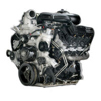
International VT 275 V6 Manual (113 pages)
Brand:
International
| Category:
Engine
| Size: 15.49 MB
Table of Contents
Safety Information
2
Safety Instructions
2
Table of Contents
3
Direct Injection Turbocharged Diesel Engine
5
Vt 275 Overview
6
Vt 275 Engine Specifications
6
Horsepower and Torque
6
Engine Serial Number
7
Emissions Label
7
Cylinder Numbering
7
Component Locations - Front of Engine
8
Component Locations - Left Front of Engine
9
Component Locations - Left Side of Engine
10
Component Locations - Left Rear of Engine
11
Component Locations - Rear of Engine
12
Component Locations - Right Rear of Engine
13
Component Locations - Right Side of Engine
14
Component Locations - Right Front of Engine
15
Component Locations - Top of Engine Without Harness
16
Component Locations - Top of Engine with Harness
17
Vt 275 Design Features
18
Cylinder Head Assembly
18
Rocker Arm Carrier
18
Crankcase Assembly
19
Crankcase and Oil Pan
19
Gear Timing
20
Rear Gear Train
20
Offset Crankpins
21
Balance Shaft Timing
21
System Features
22
Electronic Control System
22
Ecm
23
IDM
23
EGR Drive Module
24
Inlet Air Heater Element
24
Injection Pressure Regulator (IPR) Valve
25
Glow Plug Relay
25
Inlet Air Heater Relay
25
Boost Control Solenoid
26
Exhaust Gas Recirculation (EGR) Valve
26
Mass Air Flow (MAF) Sensor
26
ECM Relay Circuit Operation
27
Key Power
27
Shut down
27
IDM Relay Circuit Operation
28
IDM Power up
28
IDM Logic
28
Engine Coolant Temperature (ECT) Sensor
29
Engine Oil Temperature (EOT) Sensor
29
Sensor Circuit
29
Temperature Sensor Operation
29
Engine Oil Pressure Switch (EOPS)
30
Pressure Sensor Operation
30
Manifold Absolute Pressure (MAP) Sensor
30
Injection Control Pressure (ICP) Sensor
30
Magnetic Pick-Up Sensors
31
Camshaft Position (CMP) Sensor
31
Crankshaft Position (CKP) Sensor
31
Glow Plug System
32
Relay Operation
32
Glow Plug Lamp
32
Glow Plug Diagnostics
32
Inlet Air Heater Diagnostics
33
Inlet Air Heater Operation
33
Sensor Operation
34
Sensor Construction
34
Pump Operation
35
Fuel Heater
35
Water-In-Fuel Sensor
35
Accelerator Pedal Position Sensor / Idle Validation Switch
36
Barometric Absolute Pressure (BAP) Sensor
36
Cruise Control
36
Drive Module Operation
37
Communication
37
EGR Valve
37
EGR System
37
Crank Position Output (CKPO)
38
Cam Position Output (CMPO)
38
ECM/IDM Communications
38
A/C Clutch Control
39
A/C Demand
39
A/C Control
39
Switches
39
Air Management System
40
System Operation
41
Air Filter Restriction Gauge
42
Intake Manifold
42
Intake Flow
43
Two-Stage Regulated Turbocharger
43
Exhaust Flow
43
Exhaust Bypass Valve
44
Diverted Exhaust Gas Flow
44
Turbocharger Actuator
45
Actuator Line Routing
45
Turbocharger Crossover Tube
46
Turbocharger Mounting
46
EGR Flow
47
Fuel Supply System
48
Horizontal Fuel Conditioning Module
50
Primary Fuel Filter and Fuel Heater
50
Fuel Inlet Check Valves
51
Secondary Fuel Filter
51
Fuel Pressure Regulator Valve
51
Fuel Management System
52
Oil Reservoir
54
High Pressure Pump
54
Injection Pressure Regulator
54
Injection Control Pressure Sensor
55
High Pressure Oil Rail
55
Port Plugs and Tubes
55
Fuel Injector Features
56
Injector Operation
56
Nozzle
57
Intensifier Piston
57
Barrel & Plunger
57
Spool Valve
57
Fill
58
Injection
58
End of Injection
59
Injector Sealing
59
Lubrication System
60
Upper and Lower Oil Pan
62
Front Cover Oil Flow
62
Gerotor Pump
63
Oil Pressure Regulator Valve
63
Oil Cooler
64
Oil Cooler Housing and Oil Filter Base
64
Oil Filter
65
Oil Filter Bypass
65
Oil Filter Base and Valves
66
Reservoir and Screen
66
Turbocharger Feed Line
67
Crankcase Oil and Coolant Passages
67
System Features and Flow
68
Cooling System
68
Coolant Flow/Oil Cooler
69
Crankcase Flow
69
Front Cover Flow
69
EGR Cooler Flow
70
EGR Cooler Seal
70
Glow Plug and Injector Sleeves
70
Service Intervals
71
Belt Routing
71
Removing Flywheel Adapter
72
Removing Seal
72
Unique Repair Procedures
72
Seal Installer Base
73
Installing Seal & Wear Sleeve
73
Flexplate Bolts
73
Removing Turbocharger
74
Removing Mounting Bolts
74
Turbocharger Removal
74
Replacing O-Rings
75
Turbocharger Installation
75
Torque Turbine Mating Clamp
75
Replacing Turbocharger Crossover Seal
76
Installing Seal
76
Removing EGR Valve
77
Injector Removal
77
Injector Connectors
77
Case-To-Head Tube Installation
78
Injector Installation
78
O-Ring Replacement
78
Position Crankshaft for Rocker Removal
79
Installing Spring Compressor Base
79
Compressor Plate
79
Cylinder Head Removal: Rocker Carrier
80
Installing Head and Carrier
81
Intake Manifold Gaskets
81
Cylinder Head Torque Sequence
82
Vibration Damper
82
Connecting Rod
83
Crankshaft Flange Bolts
83
Primary Balance Weight Removal
84
Front Cover Removal
84
Rear Cover Removal
84
Balance Shaft Removal
85
Camshaft Timing
85
Special Tools
86
Hard Start no Start Diagnostics
90
Diagnostic Procedures
90
Performance Diagnostics
92
Diagnostic Tests
94
Measure Fuel Pressure
94
Check for Fuel Aeration
94
Measure Fuel Pump Discharge Pressure
95
Measure Fuel Inlet Restriction
95
Measure Crankcase Pressure
96
ICP System Checks
96
ICP System Function Test
97
IPR Function Test
97
Under Valve Cover Leak Test
98
Cylinder Head Isolation
98
High Pressure Pump Test
99
ICP Diagnostics
99
Diagnostic Trouble Codes
100
Engine & Chassis Schematic
102
Power Distribution Center Fuses
104
Glossary
106
Index
108
Advertisement
Advertisement
Related Products
International VT 365
International HS 2.8L
International Categories
Tractor
Engine
Lawn Mower
Tool Storage
Snow Blower
More International Manuals
Login
Sign In
OR
Sign in with Facebook
Sign in with Google
Upload manual
Upload from disk
Upload from URL