Sign In
Upload
Manuals
Brands
Intel Manuals
Motherboard
D815EPEA2
Intel D815EPEA2 Manuals
Manuals and User Guides for Intel D815EPEA2. We have
4
Intel D815EPEA2 manuals available for free PDF download: Technical Product Specification, Product Manual, Quick Reference, Product Brief
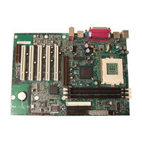
INTEL D815EPEA2 Technical Product Specification (146 pages)
Desktop Board
Brand:
INTEL
| Category:
Motherboard
| Size: 0.96 MB
Table of Contents
Revision History
2
Intended Audience
3
What this Document Contains
3
Table of Contents
5
Product Description
11
Tables
12
Board Differences
12
Feature Level Differences
12
Summary of Board Differences
12
Identifying Universal Boards
13
Location of Universal Board Designator
13
Overview
14
Feature Summary
14
Manufacturing Options
15
Board Layout
16
Board Components
16
Block Diagrams
17
Block Diagram for the D815EEA2 Board
17
Block Diagram for the D815EPEA2 Board
18
Online Support
19
Operating System Support
19
Design Specifications
20
Figures
13
Specifications
20
Processor
23
Supported Processors
23
System Memory
24
Supported Memory Configurations
25
Chipsets
26
Intel ® 815E Chipset
26
Intel 815E Chipset Block Diagram
26
USB Port Configurations
29
Intel ® 815EP Chipset
31
Intel 815EP Chipset Block Diagram
31
USB Port Configurations
34
I/O Controller
36
Serial Ports
36
Parallel Port
37
Diskette Drive Controller
37
Keyboard and Mouse Interface
37
Graphics Subsystems
38
Intel 815E Graphics Subsystem
38
Supported Graphics Refresh Frequencies
39
Intel 815EP Graphics Subsystem
42
Audio Subsystem
43
AD1885 Audio Codec
43
Audio Connectors
43
Block Diagram of Audio Subsystem
43
LAN Subsystem (Optional)
45
Intel ® 82562ET Platform LAN Connect Device
45
LAN Connector Leds
45
LAN Connector LED States
45
Hardware Management Subsystem
46
Hardware Monitor Component
46
Chassis Intrusion Detect Connector (Optional)
46
Fan Control and Monitoring
47
CNR Connector (Optional)
47
ICH2 and CNR Signal Interface
47
Power Management
48
Software Support
48
Effects of Pressing the Power Switch
49
Power States and Targeted System Power
50
Wake up Devices and Events
51
Hardware Support
52
Fan Connector Descriptions
53
Using the Wake on LAN Technology Connector
54
Location of Standby Power Indicator LED
55
Technical Reference
57
Introduction
57
Memory Map
57
System Memory Map
57
I/O Map
58
DMA Channels
60
PCI Configuration Space Map
60
Interrupts
61
PCI Interrupt Routing Map
61
PCI Interrupt Routing Map
62
Connectors
63
Back Panel Connectors
64
Overcurrent Protection for Back Panel Connectors
65
PS/2 Mouse/Keyboard Connectors
65
USB Connectors
65
VGA Port Connector (Present Only on D815EEA2 Boards)
65
Parallel Port Connector
66
Serial Port a Connector
66
LAN Connector (Optional)
67
MIC in Connector
67
Audio Line out Connector
67
Audio Line in Connector
67
Internal I/O Connectors
68
Audio, Video, Power, and Hardware Control Connectors
69
Auxiliary Line in Connector (J6B4)
70
Front Panel Audio Connector (J6B2) (Optional)
70
ATAPI CD-ROM Connector (J6B3)
70
Digital Video out Connector (J5C1) (Optional; Present Only on D815EEA2 Boards)
71
Processor Fan Connector (J1B1)
71
Power Connector (J4H1)
71
Chassis Fan Connector J4G1 (Optional)
72
System Fan Connector (J9H1)
72
Chassis Intrusion Connector (J9H3) (Optional)
72
Wake on LAN Technology Connector (J9G1) (Optional)
72
Add-In Board and Peripheral Interface Connectors
73
CNR Connector (J11B1) (Optional)
74
PCI Bus Connectors (J7B1, J8B2, J9B2, J9B1, and J10B1)
75
AGP Universal Connector (J6C1)
76
Diskette Drive Connector (J6H2)
77
IDE Connectors (J6H1, Primary and J6G2, Secondary)
77
External I/O Connectors
78
Serial Port B Connector (J8H1)
79
Front Panel USB Connector (J8F1) (Optional)
79
Auxiliary Front Panel Power LED Connector (J9H2)
79
SCSI LED Connector (J8H2)
79
Front Panel Connector (J9H3)
80
States for a Single-Colored Power LED
81
States for a Dual-Colored Power LED
81
Jumper Blocks
82
Front Panel Audio Connector/Jumper Block
82
Locations of the Jumper Blocks
82
BIOS Setup Configuration Jumper Block
83
Front Panel Audio Connector / Jumper Block (J6B2)
83
BIOS Setup Configuration Jumper Settings (J9G2)
83
Mechanical Considerations
84
Form Factor
84
Board Dimensions
84
I/O Shields
85
I/O Shield Dimensions (for D815EEA2 Universal Boards with Onboard LAN Subsystem)
86
I/O Shield Dimensions
87
I/O Shield Dimensions (for D815EPEA2 Universal Boards Without Onboard LAN Subsystem)
88
I/O Shield Dimensions (for D815EEA2 Boards with Onboard LAN Subsystem)
89
I/O Shield Dimensions (for D815EPEA2 Boards with Onboard LAN Subsystem)
90
I/O Shield Dimensions (for D815EPEA2 Boards Without Onboard LAN Subsystem)
91
Electrical Considerations
92
Power Consumption
92
Power Usage for a D815EEA2 Board with Onboard LAN
93
Power Usage for a D815EPEA2 Board with Add-In Graphics Card, Without Onboard LAN
93
Add-In Board Considerations
94
Standby Current Requirements
94
Fan Connector Current Capability
95
Power Supply Considerations
95
Thermal Considerations
96
Localized High Temperature Zones
96
Reliability
97
Thermal Considerations for Components
97
Environmental
98
D815EEA2 and D815EPEA2 Board Environmental Specifications
98
Regulatory Compliance
99
Safety Regulations
99
EMC Regulations
99
Product Certification Markings (Board Level)
100
Overview of BIOS Features
101
Introduction
101
BIOS Flash Memory Organization
102
Resource Configuration
102
PCI Autoconfiguration
102
IDE Support
102
System Management BIOS (SMBIOS)
103
Legacy USB Support
104
BIOS Updates
105
Language Support
105
Custom Splash Screen
105
Recovering BIOS Data
106
Boot Options
107
CD-ROM and Network Boot
107
Booting Without Attached Devices
107
Fast Booting Systems with Intel ® Rapid BIOS Boot
107
Peripheral Selection and Configuration
108
Intel Rapid BIOS Boot
108
Operating System Selection
108
BIOS Security Features
109
Supervisor and User Password Functions
109
BIOS Setup Program
111
Introduction
111
BIOS Setup Program Menu Bar
111
Maintenance Menu
112
BIOS Setup Program Function Keys
112
Extended Configuration Submenu
113
Main Menu
114
Advanced Menu
115
PCI Configuration Submenu
116
Boot Configuration Submenu
117
Peripheral Configuration Submenu
118
IDE Configuration Submenu
120
Primary/Secondary IDE Master/Slave Submenus
121
Diskette Configuration Submenu
123
Event Log Configuration Submenu
124
Video Configuration Submenu
125
Security Menu
126
Power Menu
127
APM Submenu
128
ACPI Submenu
129
Boot Menu
130
Boot Device Priority Submenu
131
Hard Disk Drives Submenu
132
Removable Devices Submenu
132
Removeable Devices Submenu
132
ATAPI CDROM Drives Submenu
133
Exit Menu
133
Error Messages and Beep Codes
135
BIOS Error Messages
135
Port 80H POST Codes
137
Uncompressed INIT Code Checkpoints
137
Boot Block Recovery Code Checkpoints
137
Runtime Code Uncompressed in F000 Shadow RAM
138
Bus Initialization Checkpoints
141
Upper Nibble High Byte Functions
141
Speaker
142
Lower Nibble High Byte Functions
142
BIOS Beep Codes
143
Beep Codes
143
Diagnostic Leds (Optional)
144
Diagnostic Leds
144
Diagnostic LED Codes
145
Advertisement
Intel D815EPEA2 Product Manual (96 pages)
Desktop Board Universal Platforms for 370-pin Processors
Brand:
Intel
| Category:
Motherboard
| Size: 1.12 MB
Table of Contents
Revision History
2
Table of Contents
3
Tables
9
Desktop Board Features
9
Feature Summary
9
Manufacturing Options
11
Components
12
D815EEA2 and D815EPEA2 Desktop Board Components
12
D815EFV and D815EPFV Desktop Board Components
13
Processors
14
Main Memory
15
Chipsets
16
Figures
12
Processor and Memory Module Combinations
16
Intel ® 82815E Graphics Memory Controller Hub (GMCH)
17
Intel ® 82815EP Memory Controller Hub (MCH)
17
Intel ® 82801BA I/O Controller Hub (ICH2)
17
Firmware Hub (FWH)
18
Input/Output (I/O) Controller
18
Real-Time Clock
18
USB Support
18
PCI Enhanced IDE Interface
19
Add-In Card Connectors
19
AGP Universal Connector
19
Audio Subsystem
20
Bios
20
PCI Auto Configuration
20
IDE Auto Configuration
20
Security Passwords
21
Speaker
21
LAN Subsystem (Optional)
21
Intel ® 82562ET Platform LAN Connect Device
21
LAN Subsystem Software
22
RJ-45 LAN Connector Leds
22
Battery
22
Power Management Features
22
Wake on LAN Technology (Optional)
23
Instantly Available Technology
23
Resume on Ring
24
Location of Standby Power Indicator (the D815EEA2 Board Is Shown)
24
Installing and Replacing Desktop Board Components
25
Before You Begin
25
Installing and Removing Memory
26
DIMM Installation Guidelines
26
Installing Dimms
26
Removing Dimms
27
DIMM Socket Locations (the D815EEA2 Board Is Shown)
27
Installing and Removing the AGP Card Retention Mechanism
28
Installing the AGP Card Retention Mechanism
28
Retention Notch Shown on an AGP Card
28
AGP Connector Location and Retention Mechanism (RM) Placement (Inset) (the D815EEA2 Board Is Shown)
29
Removing the AGP Card Retention Mechanism
30
Installing and Removing AGP and GPA Cards
31
Installing an AGP Card
31
Removing the AGP Card from the Retention Mechanism
31
Installing and Removing the AGP Card
31
Installing and Removing a GPA Card (D815EEA2 and D815EFV Only)
32
Installing and Removing a GPA Card
32
Installing the I/O Shield
33
Installing the Desktop Board
34
Location of the Mounting Screw Holes for the D815EEA2 and D815EPEA2 Boards
34
Location of the Mounting Screw Holes for the D815EFV and D815EPFV Boards
35
Installing a Processor
36
Installing the Processor in the Processor Socket
36
Attaching the Heatsink to the Processor
37
Attaching the Fan Heatsink Clips to the Processor Socket
37
Removing the Processor
38
Connecting the Processor Fan Cable to the Processor Fan Connector
38
Installing a 1 Ghz Processor Fan Heatsink
39
Attaching the Fan Heatsink over the Processor
39
Placing the Plastic Clip on the Fan Heatsink
39
Lowering the Plastic Clip Handle
40
Attaching the Fan to the Fan Heatsink
41
Connecting the Processor Fan Cable to the Processor Fan Connector
41
Removing the 1 Ghz Processor Fan Heatsink
42
Removing the Fan Heatsink
42
Replacing the Battery
43
Replacing the Battery on the D815EEA2 and D815EPEA2 Boards
45
Removing the Battery from the D815EEA2 and D815EPEA2 Boards
45
Replacing the Battery on the D815EFV and D815EPFV Boards
46
Removing the Battery from the D815EFV and D815EPFV Boards
46
Connecting the IDE Cable
47
Connecting the IDE Cable (the D815EEA2 Board Is Shown)
47
Setting the BIOS Configuration Jumper
48
BIOS Configuration Jumper Block Location (the D815EEA2 Board Is Shown)
48
Jumper Settings for the BIOS Setup Program Modes
48
Clearing the Passwords
49
Updating the BIOS
51
Updating the BIOS with the Intel ® Express BIOS Update Utility
51
Updating the BIOS with the Intel ® Flash Memory Update Utility
51
Preparing for the Update
51
Obtaining the BIOS Update File
52
Saving the Current BIOS Settings
52
Creating Bootable Media
52
Creating a BIOS Update Media
53
Updating the BIOS
54
Recovering the BIOS
55
Using the Setup Program
57
BIOS Setup Program Modes
57
BIOS Setup Program Menu Bar
57
Maintenance Menu
58
BIOS Setup Program Function Keys
58
Extended Configuration Submenu
59
Main Menu
60
Advanced Menu
61
PCI Configuration Submenu
62
Boot Configuration Submenu
63
Peripheral Configuration Submenu
64
IDE Configuration Submenu
66
Primary/Secondary IDE Master/Slave Submenus
67
Diskette Configuration Submenu
68
Event Log Configuration Submenu
69
Video Configuration Submenu
70
Security Menu
71
Power Menu
72
APM Submenu
73
ACPI Submenu
73
Boot Menu
74
Boot Device Priority Submenu
75
Hard Disk Drives Submenu
76
Removable Devices Submenu
76
Removeable Devices Submenu
76
ATAPI CDROM Drives
77
Exit Menu
77
ATAPI CDROM Drives Submenu
77
Technical Reference
79
Desktop Board Connectors
79
Connector Groups (the D815EEA2 Board Is Shown)
79
Back Panel Connectors
80
Back Panel Connectors (the D815EEA2 Board Is Shown)
80
Midboard Connectors
81
Audio Connectors (the D815EEA2 Board Is Shown)
81
Power and Hardware Control Connectors (the D815EEA2 Board Is Shown)
82
Add-In Board and Peripheral Interface Connectors for the D815EEA2 and D815EPEA2 Boards
83
Add-In Board and Peripheral Interface Connectors for the D815EFV and D815EPFV Boards
84
Front Panel Connectors
85
Front Panel Connectors (the D815EEA2 Board Is Shown)
85
Desktop Board Resources
86
Interrupts
86
A Error Messages and Indicators BIOS Beep Codes
87
Beep Codes
87
BIOS Error Messages
88
B Regulatory Compliance
91
Safety Regulations
91
EMC Regulations
91
Product Certification Markings
92
Installation Precautions
93
Installation Instructions
93
Ensure Electromagnetic Compatibility (EMC) Compliance
93
Chassis and Component Certifications
94
Prevent Power Supply Overload
94
Place Battery Marking
94
Use Only for Intended Applications
95
Intel D815EPEA2 Quick Reference (40 pages)
Desktop Boards
Brand:
Intel
| Category:
Computer Hardware
| Size: 0.81 MB
Table of Contents
D815Efv, and D815Epfv Universal Platforms for 370-Pin Processors Quick Reference
1
Table of Contents
1
Processors
4
Processor and Memory Module Combinations
5
7P„V…€Á5€FƒIá6€X€Ypy…„Áq€ƒÁ7%"884Áfyiá7%"8I84
6
7P„V…€Á5€FƒIá6€X€Ypy…„Áq€ƒÁ7%"89Uáfyiá7%"8I9U
8
By„…Fwwf…T€Yár…P„Á
10
T„Tyrá…Spá5Bhrá6€Yqtr†ƒF…T€YáC†XPƒ
18
D815Efv D815Epfv 370
21
D815Eea2 D815Epea2
26
D815Efv D815Epfv
28
Agp
31
Agp Gpa
36
Ide
36
Bios
38
CD-Rom
38
Intel
38
Intel ® D815EEA2 D815EPEA2 D815EFV D815EPFV
39
Advertisement
Intel D815EPEA2 Product Brief (4 pages)
Desktop Boards For Intel Pentium III and Intel Celeron Processors Solid Performance and Outstanding Flexibility
Brand:
Intel
| Category:
Motherboard
| Size: 0.18 MB
Advertisement
Related Products
Intel D815EEA2
INTEL D815EEEA2
Intel D815EEA2U - P3 Socket 370 ATX Motherboard
Intel D815EFV - Desktop Board Motherboard
Intel D815EGEWLU - P3 Socket 370 MicroATX Motherboard
Intel D815EGEW
Intel D815EPFV
Intel D810E2CA3
Intel D865GVHZ
INTEL D865GBF
Intel Categories
Motherboard
Computer Hardware
Server
Server Board
Desktop
More Intel Manuals
Login
Sign In
OR
Sign in with Facebook
Sign in with Google
Upload manual
Upload from disk
Upload from URL