Intel D815EEA2 Technical Product Specification
Desktop board
Hide thumbs
Also See for D815EEA2:
- Product brief (4 pages) ,
- Product manual (96 pages) ,
- Quick reference (40 pages)
Table of Contents
Advertisement
Quick Links
Intel
D815EEA2/D815EPEA2
Technical Product Specification
®
The Intel
Desktop Boards D815EEA2 and D815EPEA2 may contain design defects or errors known as errata that may cause the product to deviate from published
specifications. Current characterized errata are documented in the Intel Desktop Board D815EEA2/D815EPEA2 Specification Update.
Desktop Board
®
May 2001
Order Number A46399-002
Advertisement
Table of Contents

Related Manuals for Intel D815EEA2


Summary of Contents for Intel D815EEA2
- Page 1 ® The Intel Desktop Boards D815EEA2 and D815EPEA2 may contain design defects or errors known as errata that may cause the product to deviate from published specifications. Current characterized errata are documented in the Intel Desktop Board D815EEA2/D815EPEA2 Specification Update.
-
Page 2: Revision History
Intel products including liability or warranties relating to fitness for a particular purpose, merchantability, or infringement of any patent, copyright or other intellectual property right. Intel products are not intended for use in medical, life saving, or life sustaining applications. -
Page 3: Intended Audience
Preface This Technical Product Specification (TPS) specifies the board layout, components, connectors, power and environmental requirements, and the BIOS for these Intel Desktop Boards: D815EEA2 and D815EPEA2. It describes the standard product and available manufacturing options. Intended Audience The TPS is intended to provide detailed, technical information about the D815EEA2 and D815EPEA2 boards and their components to the vendors, system integrators, and other engineers and technicians who need this level of information. - Page 4 When used in the description of a component, N indicates component type, xn are the relative coordinates of its location on the D815EEA2 and D815EPEA2 boards, and X is the instance of the particular part at that general location. For example, J5J1 is a connector, located at 5J. It is the first connector in the 5J area.
-
Page 5: Table Of Contents
1.9.2 Parallel Port....................37 1.9.3 Diskette Drive Controller................37 1.9.4 Keyboard and Mouse Interface..............37 1.10 Graphics Subsystems....................38 1.10.1 Intel 815E Graphics Subsystem ..............38 1.10.2 Intel 815EP Graphics Subsystem ..............42 1.11 Audio Subsystem......................43 1.11.1 AD1885 Audio Codec...................43 1.11.2 Audio Connectors..................43 1.12 LAN Subsystem (Optional) ..................45 ®... - Page 6 Intel Desktop Board D815EEA2/D815EPEA2 Technical Product Specification DMA Channels ......................60 PCI Configuration Space Map ..................60 Interrupts ........................61 PCI Interrupt Routing Map ..................61 Connectors .........................63 2.8.1 Back Panel Connectors................64 2.8.2 Internal I/O Connectors ................68 2.8.3 External I/O Connectors ................78 Jumper Blocks ......................82 2.9.1...
- Page 7 Diagnostic LEDs (Optional)..................144 Figures Location of Universal Board Designator..............13 Board Components.....................16 Block Diagram for the D815EEA2 Board ..............17 Block Diagram for the D815EPEA2 Board ..............18 Intel 815E Chipset Block Diagram ................26 USB Port Configurations.....................29 Intel 815EP Chipset Block Diagram ................31 USB Port Configurations.....................34...
- Page 8 I/O Shield Dimensions (for D815EPEA2 Universal Boards without Onboard LAN Subsystem)......................88 I/O Shield Dimensions (for D815EEA2 Boards with Onboard LAN Subsystem) ..89 I/O Shield Dimensions (for D815EPEA2 Boards with Onboard LAN Subsystem)..90 I/O Shield Dimensions (for D815EPEA2 Boards without Onboard LAN Subsystem) ........................91...
- Page 9 Front Panel Audio Connector / Jumper Block (J6B2) ..........83 BIOS Setup Configuration Jumper Settings (J9G2) ............83 Power Usage for a D815EEA2 Board with Onboard LAN ...........93 Power Usage for a D815EPEA2 Board with Add-in Graphics Card, without Onboard LAN ....................93 Standby Current Requirements ..................94...
- Page 10 Intel Desktop Board D815EEA2/D815EPEA2 Technical Product Specification Hard Disk Drives Submenu..................132 Removeable Devices Submenu................132 ATAPI CDROM Drives Submenu................133 Exit Menu .........................133 BIOS Error Messages....................135 Uncompressed INIT Code Checkpoints..............137 Boot Block Recovery Code Checkpoints..............137 Runtime Code Uncompressed in F000 Shadow RAM..........138 Bus Initialization Checkpoints ...................141...
-
Page 11: Product Description
1 Product Description What This Chapter Contains Board Differences.......................12 Overview ........................14 Online Support......................19 Operating System Support..................19 Design Specifications ....................20 Processor ........................23 System Memory......................24 Chipsets ........................26 I/O Controller ......................36 1.10 Graphics Subsystems....................38 1.11 Audio Subsystem......................43 1.12 LAN Subsystem (Optional) ..................45 1.13 Hardware Management Subsystem................46 1.14 CNR Connector (Optional)..................47 1.15 Power Management....................48... -
Page 12: Board Differences
Intel Desktop Board D815EEA2/D815EPEA2 Technical Product Specification 1.1 Board Differences 1.1.1 Feature Level Differences ® This TPS describes these Intel Desktop boards: D815EEA2 and D815EPEA2. Table 1 summarizes the differences between these boards. Table 1. Summary of Board Differences ®... -
Page 13: Identifying Universal Boards
Product Description 1.1.2 Identifying Universal Boards The Universal versions of the D815EEA2 and D815EPEA2 can be identified by an uppercase “U” on the silkscreen of the board. Figure 1 shows the location of the Universal board designator. INTEL DESKTOP BOARD... -
Page 14: Overview
Intel Desktop Board D815EEA2/D815EPEA2 Technical Product Specification 1.2 Overview 1.2.1 Feature Summary Table 2 summarizes the D815EEA2 and D815EPEA2 boards’ major features. Table 2. Feature Summary Form Factor ATX (11.55 inches by 8.20 inches) ® ® Processor Support for either an Intel... -
Page 15: Manufacturing Options
Table 4, page 20 1.2.2 Manufacturing Options Table 3 describes the D815EEA2 and D815EPEA2 boards’ manufacturing options. Not every manufacturing option is available in all marketing channels. Please contact your Intel representative to determine which manufacturing options are available to you. -
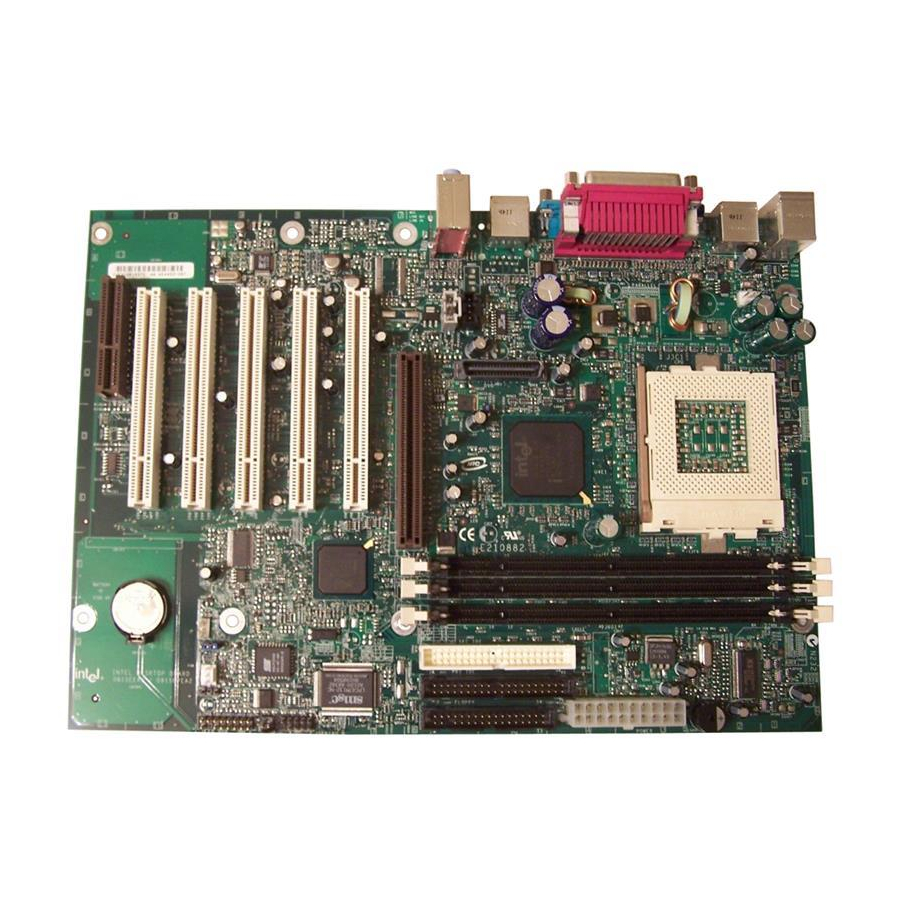
Page 16: Board Layout
Intel Desktop Board D815EEA2/D815EPEA2 Technical Product Specification 1.2.3 Board Layout Figure 2 shows the location of the major components on the D815EEA2 and D815EPEA2 boards. Present only on D815EEA2 boards OM11461 Communication and Networking Riser (CNR) Primary IDE connector connector (optional) -
Page 17: Block Diagrams
Product Description 1.2.4 Block Diagrams Figure 3 is a block diagram of the major functional areas of the D815EEA2 board. Primary/ ATA-66/100 Secondary IDE USB Ports 0 and 1 Processor Socket System Bus USB Ports 2 and 3 815E Chipset... -
Page 18: Block Diagram For The D815Epea2 Board
Intel Desktop Board D815EEA2/D815EPEA2 Technical Product Specification Figure 4 is a block diagram of the major functional areas of the D815EPEA2 board. Primary/ ATA-66/100 Secondary IDE USB Ports 0 and 1 Processor Socket System Bus USB Ports 2 and 3... -
Page 19: Online Support
Audio software and utilities http://www.intel.com/design/motherbd LAN software and drivers http://www.intel.com/design/motherbd 1.4 Operating System Support The D815EEA2 and D815EPEA2 boards support drivers for all of the onboard hardware and subsystems under the following operating systems: † Windows 98/98SE Windows ME †... -
Page 20: Design Specifications
Intel Desktop Board D815EEA2/D815EPEA2 Technical Product Specification 1.5 Design Specifications Table 4 lists the specifications applicable to the D815EEA2 and D815EPEA2 boards, except for the AIMM and GPA entries, which apply only to the D815EEA2 board. Table 4. Specifications Reference... - Page 21 PCI Bus Power Version 1.1, http://www.pcisig.com/ Management Interface December 18, 1998, Specification PCI Special Interest Group. Plug and Plug and Play BIOS Version 1.0a, http://www.microsoft.com/ Play Specification May 5, 1994, hwdev/respec/ Compaq Computer Corporation, pnpspecs.htm Phoenix Technologies Limited, and Intel Corporation. continued...
- Page 22 Intel Desktop Board D815EEA2/D815EPEA2 Technical Product Specification Table 4. Specifications (continued) Reference Specification Version, Revision Date The information is Name Title and Ownership available from… SDRAM PC SDRAM Unbuffered Revision 1.0, http://www.intel.com/ DIMM Specification February 1998, technology/memory Intel Corporation. PC SDRAM Specification Revision 1.7,...
-
Page 23: Processor
Use only the processors listed below. Use of unsupported processors can damage the board, the processor, and the power supply. See the Intel Desktop D815EEA2/D815EPEA2 Specification Update for the most up-to-date list of supported processors for the D815EEA2 and D815EPEA2 boards. -
Page 24: System Memory
DIMMs may not function under the determined frequency. The D815EEA2 and D815EPEA2 boards both have three DIMM sockets and support the following memory features: 3.3 V (only) 168-pin SDRAM DIMMs with gold-plated contacts Unbuffered single-sided or double-sided DIMMs Maximum total system memory: 512 MB;... -
Page 25: Supported Memory Configurations
Product Description NOTE If more than four rows of 133 MHz SDRAM are populated, the BIOS will display a message indicating that it will initialize installed memory up to 512 MB at 100 MHz. For information about Refer to Obtaining the PC Serial Presence Detect (SPD) Specification Table 4, page 19 Table 6 lists the supported DIMM configurations. -
Page 26: Chipsets
1.8 Chipsets This section describes the chipsets used by the D815EEA2 and D815EPEA2 boards: The D815EEA2 board uses the Intel 815E Chipset, described below. The D815EPEA2 board uses the Intel 815EP Chipset, described in Section 1.8.2, beginning on page 31. ®... - Page 27 Product Description ® 1.8.1.1 Intel 82815 Graphics and Memory Controller Hub (GMCH) The GMCH provides the following: An integrated Synchronous DRAM memory controller with autodetection of SDRAM An interface for a single AGP device or a Graphics Performance Accelerator (GPA) card...
- Page 28 The ICH2 contains two separate USB controllers. The D815EEA2 board has four USB ports; one USB peripheral can be connected to each port. For more than four USB devices, an external hub can be connected to any of the ports. The D815EEA2 board fully supports the Universal Hub Controller Interface (UHCI).
-
Page 29: Usb Port Configurations
Product Description Standard Configuration USB ports 0 and 1 Back panel USB connectors 82801BA I/O Controller Hub (ICH2) USB ports 2 and 3 Back panel USB connectors Optional Configuration USB ports 0 and 2 Back panel USB connectors 82801BA I/O Controller Hub (ICH2) USB port accesible through a USB CNR connector... - Page 30 Intel Desktop Board D815EEA2/D815EPEA2 Technical Product Specification 1.8.1.2.3 Real-Time Clock, CMOS SRAM, and Battery The real-time clock provides a time-of-day clock and a multicentury calendar with alarm features. The real-time clock supports 256 bytes of battery-backed CMOS SRAM in two banks that are reserved for BIOS use.
-
Page 31: Intel ® 815Ep Chipset
The MCH is a centralized controller for the system bus, the memory bus, the AGP bus, and the AHA bus. The ICH2 is a centralized controller for the board’s I/O paths. The FWH provides the nonvolatile storage of the BIOS. The Intel 815EP chipset provides the interfaces shown in Figure 7. ATA-66/100 Network... - Page 32 Intel Desktop Board D815EEA2/D815EPEA2 Technical Product Specification ® 1.8.2.1 Intel 82815EP Memory Controller Hub (MCH) The MCH provides the following: An integrated Synchronous DRAM memory controller with autodetection of SDRAM An interface for a single AGP device Support for ACPI Rev. 2.0 and APM Rev. 1.2 compliant power management 1.8.2.2...
- Page 33 The drive reports the transfer rate and translation mode to the BIOS. The D815EEA2 board supports Laser Servo (LS-120) diskette technology through its IDE interfaces. The LS-120 drive can be configured as a boot device by setting the BIOS Setup program’s Boot menu to one of the following:...
-
Page 34: Usb Port Configurations
Intel Desktop Board D815EEA2/D815EPEA2 Technical Product Specification Standard Configuration USB ports 0 and 1 Back panel USB connectors 82801BA I/O Controller Hub (ICH2) USB ports 2 and 3 Back panel USB connectors Optional Configuration USB ports 0 and 2 Back panel USB connectors... - Page 35 Product Description 1.8.2.2.3 Real-Time Clock, CMOS SRAM, and Battery The real-time clock provides a time-of-day clock and a multicentury calendar with alarm features. The real-time clock supports 256 bytes of battery-backed CMOS SRAM in two banks that are reserved for BIOS use. A coin-cell battery (CR2032) powers the real-time clock and CMOS memory.
-
Page 36: I/O Controller
1.9.1 Serial Ports The D815EEA2 and D815EPEA2 boards each have two serial ports. Serial port A is located on the back panel. Serial port B is accessible using the connector at location J8H1. The serial ports’ NS16C550-compatible UARTs support data transfers at speeds up to 115.2 kbits/sec with BIOS support. -
Page 37: Parallel Port
Product Description 1.9.2 Parallel Port The connector for the parallel port is a 25-pin D-Sub connector located on the back panel. In the BIOS Setup program, the parallel port can be set to the following modes: † Output only (PC-AT -compatible mode) Bi-directional (PS/2 compatible) For information about... -
Page 38: Graphics Subsystems
Intel Desktop Board D815EEA2/D815EPEA2 Technical Product Specification 1.10 Graphics Subsystems This section describes the graphics subsystems used by the D815EEA2 and D815EPEA2 boards: The D815EEA2 board uses the Intel 815E graphics subsystem, described below. The D815EPEA2 board uses the Intel 815EP graphics subsystem, described in Section 1.10.2, beginning on page 42. -
Page 39: Supported Graphics Refresh Frequencies
Product Description Table 7 lists the refresh frequencies supported by the graphics subsystem. Table 7. Supported Graphics Refresh Frequencies Available Refresh Resolution Color Palette Frequencies (Hz) Notes 256 colors 320 x 200 64 K colors 16 M colors 256 colors 320 x 240 64 K colors 16 M colors... - Page 40 1.10.1.2 Digital Video Output (DVO) Connector (Optional) The D815EEA2 board routes the Intel 82815 GMCH DVO port to an optional onboard 40-pin DVO connector. The DVO connector can be cabled to a DVI or TV out card to enable digital displays or TV out functionality.
- Page 41 1.10.1.3.1 Graphics Performance Accelerator (GPA) Support The Intel 815E GMCH display cache is a single channel 32-bit wide SDRAM interface. The 4 MB display cache resides on a GPA card that plugs into the AGP connector. The BIOS detects a GPA card if present in the AGP port and initializes it as display cache memory.
-
Page 42: Intel 815Ep Graphics Subsystem
Install memory in the DIMM sockets prior to installing the AGP video card to avoid interference with the memory retention mechanism. The Intel 815EP chipset, used on the D815EPEA2 board, provides an AGP universal connector which supports a 1x, 2x, or 4x AGP add-in card with either 3.3 V or 1.5 V I/O. -
Page 43: Audio Subsystem
Full-duplex operation at asynchronous hardware record/playback samples rates Frequency response: 20 Hz to 20 kHz (± 0.1 dB) Figure 9 is a block diagram of the D815EEA2 and D815EPEA2 boards’ audio subsystem, including the Intel 82801BA ICH2 digital controller, the AD1885 analog codec, and the audio connectors. - Page 44 Intel Desktop Board D815EEA2/D815EPEA2 Technical Product Specification Back panel audio connectors: Line in Line out Mic in For information about Refer to The back panel audio connectors Section 2.8.1, page 64 1.11.2.1 Front Panel Audio Connector (Optional) A 2 x 5-pin connector for routing mic in and line out to the front panel.
-
Page 45: Lan Subsystem (Optional)
1.12.1 Intel 82562ET Platform LAN Connect Device The Intel 82562ET component provides an interface to the back panel RJ-45 connector with integrated LEDs. This physical interface may alternately be provided through the CNR connector. The Intel 82562ET provides the following functions:... -
Page 46: Hardware Management Subsystem
Intel Desktop Board D815EEA2/D815EPEA2 Technical Product Specification 1.13 Hardware Management Subsystem The hardware management features enable the board to be compatible with the Wired for Management (WfM) specification. The board has several hardware management features, including the following: Hardware monitoring... -
Page 47: Fan Control And Monitoring
Section 2.8.2.2, page 69 1.14 CNR Connector (Optional) The CNR connector supports the audio, modem, USB, and LAN interfaces of the Intel 815E and Intel 815EP chipsets. Figure 10 shows the signal interface between the riser and the ICH2. AC ’97 Interfaces... -
Page 48: Power Management
1.15.1 Software Support The software support for power management includes: ACPI If the D815EEA2 or D815EPEA2 board is used with an ACPI-aware operating system, the BIOS can provide ACPI support. Otherwise, it defaults to APM support. 1.15.1.1 APM makes it possible for the computer to enter an energy-saving standby mode. The standby... -
Page 49: Effects Of Pressing The Power Switch
ACPI gives the operating system direct control over the power management and Plug and Play functions of a computer. The use of ACPI with the D815EEA2 or D815EPEA2 board requires an operating system that provides full ACPI support. ACPI features include:... -
Page 50: Power States And Targeted System Power
The operating system uses information from applications and user settings to put the system as a whole into a low-power state. Table 10 lists the power states supported by the D815EEA2 and D815EPEA2 boards along with the associated system power targets. See the ACPI specification for a complete description of the various system and power states. -
Page 51: Wake Up Devices And Events
For the Wake on LAN technology connector and PME#, S5 is disabled by default in the BIOS Setup program. Setting these options to Power On will enable a wake-up event from LAN in the S5 state. Wake from CNR modem is not supported on the D815EEA2 and D815EPEA2 boards. NOTE The use of these wake up events from an ACPI state requires an operating system that provides full ACPI support. -
Page 52: Hardware Support
When used with an ATX-compliant power supply that supports remote power on/off, the D815EEA2 and D815EPEA2 boards can turn off the system power through software control. To enable soft-off control in software, advanced power management must be enabled in the BIOS Setup program and in the operating system. -
Page 53: Fan Connector Descriptions
Product Description 1.15.2.2 Fan Connectors The D815EEA2 and D815EPEA2 boards both have two standard fan connectors and one optional fan connector. The functions of these connectors are described in Table 12. Table 12. Fan Connector Descriptions Silkscreen Reference Connector Label... -
Page 54: Using The Wake On Lan Technology Connector
The standby power indicator LED (at location CR6E1) shows that power is still present at the DIMM and PCI bus connectors, even when the computer appears to be off. Figure 12 shows the location of the standby power indicator LED on the D815EEA2 and D815EPEA2 boards. -
Page 55: Location Of Standby Power Indicator Led
Product Description CR6E1 Present only on D815EEA2 boards OM11462 Figure 12. Location of Standby Power Indicator LED For information about Refer to The devices and events that can wake the computer from the S3 state Table 11, page 51 The PCI Bus Power Management Interface Specification... - Page 56 Intel Desktop Board D815EEA2/D815EPEA2 Technical Product Specification 1.15.2.5 Resume on Ring The operation of Resume on Ring can be summarized as follows: Resumes operation from either the APM sleep mode or the ACPI S1 state Requires only one call to access the computer...
-
Page 57: Technical Reference
2 Technical Reference What This Chapter Contains Introduction.........................57 Memory Map ......................57 I/O Map........................58 DMA Channels ......................60 PCI Configuration Space Map ..................60 Interrupts ........................61 PCI Interrupt Routing Map ..................61 Connectors .........................63 Jumper Blocks ......................82 2.10 Mechanical Considerations..................84 2.11 Electrical Considerations ....................92 2.12 Thermal Considerations....................96 2.13 Reliability ........................97 2.14 Environmental......................98... -
Page 58: I/O Map
Intel Desktop Board D815EEA2/D815EPEA2 Technical Product Specification 2.3 I/O Map Table 14. I/O Map Address (hex) Size Description 0000 - 000F 16 bytes DMA controller 0020 - 0021 2 bytes Programmable Interrupt Control (PIC) 0040 - 0043 4 bytes System timer... - Page 59 Secondary bus master IDE registers 96 contiguous bytes starting on a ICH2 (ACPI + TCO) 128-byte divisible boundary 64 contiguous bytes starting on a D815EEA2/D815EPEA2 board resource 64-byte divisible boundary 64 contiguous bytes starting on a ICH2 LAN controller 64-byte divisible boundary 64 contiguous bytes starting on a ICH2 AC ’97 audio master...
-
Page 60: Dma Channels
Intel Desktop Board D815EEA2/D815EPEA2 Technical Product Specification 2.4 DMA Channels Table 15. DMA Channels DMA Channel Number Data Width System Resource 8 or 16 bits Audio 8 or 16 bits Audio/parallel port 8 or 16 bits Diskette drive 8 or 16 bits... -
Page 61: Interrupts
Technical Reference 2.6 Interrupts Table 17. Interrupts System Resource I/O channel check Reserved, interval timer Reserved, keyboard buffer full Reserved, cascade interrupt from slave PIC (Note) COM2 (Note) COM1 LPT2 (Plug and Play option) /Audio/User available Diskette drive (Note) LPT1 Real-time clock Reserved for ICH2 system management bus User available... -
Page 62: Pci Interrupt Routing Map
PCI add-in card connect to one of these PIRQ signals. Some PCI interrupt sources are electrically tied together on the D815EEA2 and D815EPEA2 boards and therefore share the same interrupt. Table 18 shows an example of how the PIRQ signals are routed on the D815EEA2 and D815EPEA2 boards. -
Page 63: Connectors
2.8 Connectors CAUTION Only the back panel connectors of the D815EEA2 and D815EPEA2 boards have overcurrent protection. The D815EEA2 and D815EPEA2 boards’ internal connectors are not overcurrent protected and should connect only to devices inside the computer’s chassis, such as fans and internal peripherals. -
Page 64: Back Panel Connectors
Intel Desktop Board D815EEA2/D815EPEA2 Technical Product Specification 2.8.1 Back Panel Connectors Figure 13 shows the location of the back panel connectors on the D815EEA2 and D815EPEA2 boards. The back panel connectors are color-coded in compliance with PC 99 recommendations. The figure legend below lists the colors used. -
Page 65: Overcurrent Protection For Back Panel Connectors
The back panel audio line out connector is designed to power headphones or amplified speakers only. Poor audio quality occurs if passive (non-amplified) speakers are connected to this output. Table 19 lists the overcurrent protection for the D815EEA2 and D815EPEA2 boards. Overcurrent protection is provided to the board’s back panel connectors through thermistors. -
Page 66: Parallel Port Connector
Intel Desktop Board D815EEA2/D815EPEA2 Technical Product Specification Table 23. Parallel Port Connector Standard Signal Name ECP Signal Name EPP Signal Name STROBE# STROBE# WRITE# ACK# ACK# INTR BUSY BUSY#, PERIPHACK WAIT# PERROR PE, ACKREVERSE# SELECT SELECT SELECT AUDOFD# AUDOFD#, HOSTACK... -
Page 67: Lan Connector (Optional)
Technical Reference Table 25. LAN Connector (Optional) Signal Name Ground Ground Ground Ground Table 26. Mic In Connector Signal Name Mono in Ring Mic bias voltage Sleeve Ground Table 27. Audio Line Out Connector Signal Name Audio left out Ring Audio right out Sleeve Ground... -
Page 68: Internal I/O Connectors
The internal I/O connectors are divided into the following functional groups: Audio, video, power, and hardware control (see page 69) Front panel audio (optional) ATAPI CD-ROM Auxiliary line in Digital video out (optional; present only on D815EEA2 boards) Fans Power Chassis intrusion (optional) Wake on LAN technology (optional) -
Page 69: Audio, Video, Power, And Hardware Control Connectors
Technical Reference 2.8.2.2 Audio, Video, Power, and Hardware Control Connectors Figure 14 shows the location of the audio, video, power, and hardware control connectors on the D815EEA2 and D815EPEA2 boards. Present only on D815EEA2 boards OM11464 Item Description Color Reference Designator... -
Page 70: Auxiliary Line In Connector (J6B4)
Intel Desktop Board D815EEA2/D815EPEA2 Technical Product Specification Table 29. Auxiliary Line In Connector (J6B4) Signal Name Left auxiliary line in Ground Ground Right auxiliary line in Table 30. Front Panel Audio Connector (J6B2) (Optional) Signal Name Signal Name MICIN_FP Ground... -
Page 71: Digital Video Out Connector (J5C1) (Optional; Present Only On D815Eea2 Boards)
Technical Reference Table 32. Digital Video Out Connector (J5C1) (Optional; present only on D815EEA2 boards) Signal Name Signal Name LTVCLKIN +5 V P_RST_SLOTS# LTVCL_3V Ground LTVDA_3V Ground LTVVSYNC Ground LTVHSYNC Ground LTVDAT0 Ground LTVDAT1 Ground LTVDAT2 Ground LTVDAT3 Ground LTVDAT4... -
Page 72: Chassis Fan Connector J4G1 (Optional)
Intel Desktop Board D815EEA2/D815EPEA2 Technical Product Specification Table 35. Chassis Fan Connector J4G1 (Optional) Signal Name FAN3_PWM +12 V No connect Table 36. System Fan Connector (J9H1) Signal Name FAN2_PWM +12 V FAN2_TACH Table 37. Chassis Intrusion Connector (J9H3) (Optional) -
Page 73: Add-In Board And Peripheral Interface Connectors
Add-in Board and Peripheral Interface Connectors Figure 15 shows the location of the add-in board connectors and peripheral interface connectors on the D815EEA2 and D815EPEA2 boards. Note the following considerations for the PCI bus connectors: All of the PCI bus connectors are bus master capable. -
Page 74: Cnr Connector (J11B1) (Optional)
Intel Desktop Board D815EEA2/D815EPEA2 Technical Product Specification Table 39. CNR Connector (J11B1) (Optional) Signal Name Signal Name Reserved Reserved Reserved Reserved Ground Reserved Reserved Ground Reserved Reserved Ground Reserved LAN_TXD2 Ground LAN_TXD0 LAN_TXD1 Ground LAN_RSTSYNC LAN_CLK Ground LAN_RXD1 LAN_RXD2 Reserved... -
Page 75: Pci Bus Connectors (J7B1, J8B2, J9B2, J9B1, And J10B1)
Technical Reference Table 40. PCI Bus Connectors (J7B1, J8B2, J9B2, J9B1, and J10B1) Signal Name Signal Name Signal Name Signal Name Ground (TRST#)* -12 V AD16 AD17 +12 V Ground (TCK)* +3.3 V C/BE2# +5 V (TMS)* Ground FRAME# Ground +5 V (TDI)* Not connected (TDO)* Ground... -
Page 76: Agp Universal Connector (J6C1)
Intel Desktop Board D815EEA2/D815EPEA2 Technical Product Specification Table 41. AGP Universal Connector (J6C1) Signal Name Signal Name Signal Name Signal Name +12 V Not connected Vddq Vddq TYPEDET# +5 V AD22 AD21 Reserved +5 V AD20 AD19 Not connected Not connected... -
Page 77: Diskette Drive Connector (J6H2)
Technical Reference Table 42. Diskette Drive Connector (J6H2) Signal Name Signal Name Ground DENSEL Ground Reserved FDEDIN Ground FDINDX# (Index) Ground FDM00# (Motor Enable A) Ground Not connected Ground FDDS0# (Drive Select A) Ground Not connected Not connected FDDIR# (Stepper Motor Direction) Ground FDSTEP# (Step Pulse) Ground... -
Page 78: External I/O Connectors
Intel Desktop Board D815EEA2/D815EPEA2 Technical Product Specification 2.8.3 External I/O Connectors Figure 16 shows the locations of the external I/O connectors on the D815EEA2 and D815EPEA2 boards. Present only on D815EEA2 boards OM11466 Item Description Reference Designator For more information see:... -
Page 79: Serial Port B Connector (J8H1)
Technical Reference Table 44. Serial Port B Connector (J8H1) Signal Name Signal Name DCD2# RXD2 (Receive Data) TXD2 (Transmit Data) DTR2# Ground DSR2# RTS2# CTS2# RI2# Key (no pin) Table 45. Front Panel USB Connector (J8F1) (Optional) Signal Name Signal Name VREG_FP_USB_PWR VREG_FP_USB_PWR ICH_FP0#... -
Page 80: Front Panel Connector (J9H3)
Reset Switch Connector Pins 5 and 7 can be connected to a momentary SPST type switch that is normally open. When the switch is closed, the D815EEA2 and D815EPEA2 boards reset and run the POST. 2.8.3.3.2 Hard Drive Activity LED Connector Pins 1 and 3 can be connected to an LED to provide a visual indicator that data is being read from or written to a hard drive. -
Page 81: States For A Single-Colored Power Led
SW_ON# pin to ground for at least 50 ms to signal the power supply to switch on or off. (The time requirement is due to internal debounce circuitry on the D815EEA2 and D815EPEA2 boards.) At least two seconds must pass before the power supply will recognize another on/off... -
Page 82: Jumper Blocks
Do not move any jumpers with the power on. Always turn off the power and unplug the power cord from the computer before changing a jumper setting. Otherwise, the board could be damaged. Figure 17 shows the locations of the jumper blocks on the D815EEA2 and D815EPEA2 boards. J6B2... -
Page 83: Bios Setup Configuration Jumper Block
Technical Reference Table 51. Front Panel Audio Connector / Jumper Block (J6B2) Jumper Setting Configuration Audio line out signals are routed to the back panel audio line out connector. The back panel audio line out connector is shown in Figure 13 on page 64. 5 and 6, 9 and 10 Audio line out and mic in signals are available for front panel audio connectors. -
Page 84: Mechanical Considerations
2.10 Mechanical Considerations 2.10.1 Form Factor The D815EEA2 and D815EPEA2 boards are designed to fit into a standard ATX-form-factor chassis. Figure 18 illustrates the mechanical form factor for the D815EEA2 and D815EPEA2 boards. Dimensions are given in inches [millimeters]. The outer dimensions are 11.55 inches by 8.20 inches [293.37 millimeters by 208.28 millimeters]. -
Page 85: I/O Shields
Technical Reference 2.10.2 I/O Shields The back panel I/O shields for the D815EEA2 and D815EPEA2 boards must meet specific dimension and material requirements. Systems based on this board need the back panel I/O shield to pass emissions (EMI) certification testing. Figure 19, Figure 20, and Figure 21 show the critical dimensions of the chassis-dependent I/O shield for the Universal boards. -
Page 86: I/O Shield Dimensions (For D815Eea2 Universal Boards With Onboard Lan Subsystem)
4x Dia 0.125 [3.180] 8X R0.5 MIN 0.884 [22.450] 0.519 [13.190] 0.276 0.027 [7.012] [0.690] 1.89 0.00 0.465 [11.811] 0.465 [11.811] 0.567 [14.400] 0.567 [14.400] 0.621 [15.770] Pictorial View OM11400 Figure 19. I/O Shield Dimensions (for D815EEA2 Universal Boards with Onboard LAN Subsystem) -
Page 87: I/O Shield Dimensions
Technical Reference 6.390 Ref [162.300] 0.063±0.005 [1.600±0.120] 0.787±0.010 TYP [20±0.254] 3x Dia 0.330 [8.380] 0.039 Dia. [1.000] 4x Dia 0.125 [3.180] 8X R0.5 MIN 0.884 [22.450] 0.519 [13.190] 0.276 0.027 [7.012] [0.690] 1.89 0.00 0.465 [11.811] 0.465 [11.811] 0.567 [14.400] 0.567 [14.400] 0.621... -
Page 88: I/O Shield Dimensions (For D815Epea2 Universal Boards Without Onboard Lan Subsystem)
Intel Desktop Board D815EEA2/D815EPEA2 Technical Product Specification 6.390 Ref [162.300] 0.063±0.005 [1.600±0.120] 0.787±0.010 TYP [20±0.254] 3x Dia 0.330 [8.380] 0.039 Dia. [1.000] 4x Dia 0.125 [3.180] 8X R0.5 MIN 0.884 [22.450] 0.519 [13.190] 0.276 0.027 [7.012] [0.690] 1.89 0.00 0.465 [11.811]... -
Page 89: I/O Shield Dimensions (For D815Eea2 Boards With Onboard Lan Subsystem)
3x Dia 0.330 [8.380] 8X R0.5 MIN 0.884 [22.450] 0.519 [13.190] 0.276 [7.012] 0.027 0.000 [0.690] [0.000] 0.465 0.465 [11.810] [11.811] 0.472 0.567 [12.000] [14.400] Pictorial View OM11487 Figure 22. I/O Shield Dimensions (for D815EEA2 Boards with Onboard LAN Subsystem) -
Page 90: I/O Shield Dimensions (For D815Epea2 Boards With Onboard Lan Subsystem)
Intel Desktop Board D815EEA2/D815EPEA2 Technical Product Specification 6.390 [162.300] 0.063 0.005 [1.600 0.120] 0.787 0.010 TYP [20 0.254] 3x Dia 0.039 [1.000] 3x Dia 0.330 [8.380] 8X R0.5 MIN 0.884 [22.450] 0.519 [13.190] 0.276 [7.012] 0.027 [0.690] 0.000 [0.000] 0.465 0.465... -
Page 91: I/O Shield Dimensions (For D815Epea2 Boards Without Onboard Lan Subsystem)
Technical Reference 6.390 [162.300] 0.063 0.005 [1.600 0.120] 0.787 0.010 TYP [20 0.254] 3x Dia 0.039 [1.000] 3x Dia 0.330 [8.380] 8X R0.5 MIN 0.884 [22.450] 0.519 [13.190] 0.276 [7.012] 0.027 [0.690] 0.000 [0.000] 0.465 0.465 [11.810] [11.811] 0.472 0.567 [12.000] [14.400] 0.567... -
Page 92: Electrical Considerations
Intel Desktop Board D815EEA2/D815EPEA2 Technical Product Specification 2.11 Electrical Considerations 2.11.1 Power Consumption Table 53 lists voltage and current measurements for a computer that contains either the D815EEA2 or the D815EPEA2 board and the following: 800 MHz Intel Pentium III processor with a 256 KB cache 128 MB SDRAM 3.5-inch diskette drive... -
Page 93: Power Usage For A D815Eea2 Board With Onboard Lan
Technical Reference Table 53 lists the power usage for a D815EEA2 board with the configuration listed on the previous page and including the optional onboard LAN subsystem. Table 53. Power Usage for a D815EEA2 Board with Onboard LAN DC Current at:... -
Page 94: Add-In Board Considerations
Intel Desktop Board D815EEA2/D815EPEA2 Technical Product Specification 2.11.2 Add-in Board Considerations The D815EEA2 and D815EPEA2 boards are designed to provide 2 A (average) of +5 V current for each add-in board. The total +5 V current draw for add-in boards in a fully-loaded D815EEA2 and D815EPEA2 boards (all six expansion slots filled) must not exceed 12 A. -
Page 95: Fan Connector Current Capability
CNR requirements are calculated as follows: One wake-enabled device @ 375 mA Non-wake-enabled devices @ 20 mA 2.11.4 Fan Connector Current Capability The D815EEA2 and D815EPEA2 boards are designed to supply a maximum of 225 mA per fan connector. 2.11.5 Power Supply Considerations CAUTION The +5 V standby line for the power supply must be capable of providing adequate +5 V standby current. -
Page 96: Thermal Considerations
System integrators should ensure that proper airflow is maintained in the voltage regulator circuit. Failure to do so may result in damage to the voltage regulator circuit. Figure 25 shows the locations of the localized high temperature zones for the D815EEA2 and D815EPEA2 boards. -
Page 97: Reliability
Technical Reference Table 56 provides maximum case temperatures for D815EEA2 and D815EPEA2 board components that are sensitive to thermal changes. Case temperatures could be affected by the operating temperature, current load, or operating frequency. Maximum case temperatures are important when considering proper airflow to cool the D815EEA2 and D815EPEA2 boards. -
Page 98: Environmental
Intel Desktop Board D815EEA2/D815EPEA2 Technical Product Specification 2.14 Environmental Table 57 lists the environmental specifications for the D815EEA2 and D815EPEA2 boards. Table 57. D815EEA2 and D815EPEA2 Board Environmental Specifications Parameter Specification Temperature Non-Operating -40 C to +70 C Operating 0 C to +55 C... -
Page 99: Regulatory Compliance
This section describes the D815EEA2 and D815EPEA2 boards’ compliance with U.S. and international safety and electromagnetic compatibility (EMC) regulations. 2.15.1 Safety Regulations Table 58 lists the safety regulations the D815EEA2 and D815EPEA2 boards comply with when correctly installed in a compatible host system. Table 58. -
Page 100: Product Certification Markings (Board Level)
UL joint US/Canada Recognized Component mark: Consists of lower case c followed by a stylized backward UR and followed by a small US. Includes adjacent UL file number for Intel desktop boards: E210882 (component side). FCC Declaration of Conformity logo mark for Class B equipment; to include Intel name and D815EEA2 and D815EPEA2 model designation (solder side). -
Page 101: Overview Of Bios Features
3.10 BIOS Security Features ....................109 3.1 Introduction The D815EEA2 and D815EPEA2 boards use an Intel/AMI BIOS that is stored in the Firmware Hub (FWH) and can be updated using a disk-based program. The FWH contains the BIOS Setup program, POST, APM, the PCI auto-configuration utility, and Plug and Play support. -
Page 102: Bios Flash Memory Organization
Intel Desktop Board D815EEA2/D815EPEA2 Technical Product Specification 3.2 BIOS Flash Memory Organization The FWH (an SST 49LF004A) includes a 4 Mbit (512 KB) symmetrical flash memory device. Internally, the device is grouped into eight 64-KB blocks that are individually erasable, lockable, and unlockable. -
Page 103: System Management Bios (Smbios)
Using this support, an SMBIOS service-level application running on a non-Plug and Play operating system can obtain the SMBIOS information. For information about Refer to The D815EEA2 and D815EPEA2 boards’ compliance level with the Table 4, page 20 SMBIOS specification... -
Page 104: Legacy Usb Support
Intel Desktop Board D815EEA2/D815EPEA2 Technical Product Specification 3.5 Legacy USB Support Legacy USB support enables USB devices such as keyboards, mice, and hubs to be used even when the operating system’s USB drivers are not yet available. Legacy USB support is used to access the BIOS Setup program, and to install an operating system that supports USB. -
Page 105: Bios Updates
During POST, an Intel splash screen is displayed by default. This splash screen can be replaced with a custom splash screen. A utility is available from Intel to assist with creating a custom splash screen. The custom splash screen can be programmed into the flash memory using the BIOS upgrade utility. -
Page 106: Recovering Bios Data
To create a BIOS recovery diskette, a bootable diskette must be created and the BIOS update files copied to it. BIOS upgrades and the Intel Flash Memory Upgrade utility are available from Intel Customer Support through the Intel World Wide Web site. -
Page 107: Boot Options
The BIOS is not configured by default to boot at the fastest possible speed. Empirical measurements have shown that some Intel Desktop boards, when optimized as described above, can complete POST (Power-On Self-Test) in six seconds or less and boot to an active Microsoft... -
Page 108: Peripheral Selection And Configuration
Make sure the Intel Rapid BIOS Boot option (in the Boot menu of the BIOS Setup Program) is enabled (this is typically the default setting). This feature bypasses memory count and floppy seek. -
Page 109: Bios Security Features
Overview of BIOS Features 3.10 BIOS Security Features The BIOS includes security features that restrict access to the BIOS Setup program and who can boot the computer. A supervisor password and a user password can be set for the BIOS Setup program and for booting the computer, with the following restrictions: The supervisor password gives unrestricted access to view and change all the Setup options in the BIOS Setup program. - Page 110 Intel Desktop Board D815EEA2/D815EPEA2 Technical Product Specification...
-
Page 111: Bios Setup Program
4 BIOS Setup Program What This Chapter Contains Introduction.......................111 Maintenance Menu ....................112 Main Menu........................114 Advanced Menu......................115 Security Menu......................126 Power Menu ......................127 Boot Menu ........................130 Exit Menu .........................133 4.1 Introduction The BIOS Setup program can be used to view and change the BIOS settings for the computer. The BIOS Setup program is accessed by pressing the <F2>... -
Page 112: Maintenance Menu
Intel Desktop Board D815EEA2/D815EPEA2 Technical Product Specification Table 62 lists the function keys available for menu screens. Table 62. BIOS Setup Program Function Keys BIOS Setup Program Function Key Description < > or < > Selects a different menu screen (Moves the cursor left or right) <... -
Page 113: Extended Configuration Submenu
BIOS Setup Program 4.2.1 Extended Configuration Submenu To access this submenu, select Maintenance on the menu bar, then Extended Configuration. Main Advanced Security Power Boot Exit Maintenance Extended Configuration The submenu represented by Table 64 is for setting video memory cache mode. This submenu becomes available when User Defined is selected under Extended Configuration. -
Page 114: Main Menu
Intel Desktop Board D815EEA2/D815EPEA2 Technical Product Specification 4.3 Main Menu To access this menu, select Main on the menu bar at the top of the screen. Maintenance Advanced Security Power Boot Exit Main Table 65 describes the Main Menu. This menu reports processor and memory information and is for configuring the system date and system time. -
Page 115: Advanced Menu
BIOS Setup Program 4.4 Advanced Menu To access this menu, select Advanced on the menu bar at the top of the screen. Maintenance Main Security Power Boot Exit Advanced PCI Configuration Boot Configuration Peripheral Configuration IDE Configuration Diskette Configuration Event Log Configuration Video Configuration Table 66 describes the Advanced Menu. -
Page 116: Pci Configuration Submenu
Intel Desktop Board D815EEA2/D815EPEA2 Technical Product Specification 4.4.1 PCI Configuration Submenu To access this submenu, select Advanced on the menu bar, then PCI Configuration. Maintenance Main Security Power Boot Exit Advanced PCI Configuration Boot Configuration Peripheral Configuration IDE Configuration Diskette Configuration... -
Page 117: Boot Configuration Submenu
BIOS Setup Program 4.4.2 Boot Configuration Submenu To access this submenu, select Advanced on the menu bar, then Boot Configuration. Maintenance Main Security Power Boot Exit Advanced PCI Configuration Boot Configuration Peripheral Configuration IDE Configuration Diskette Configuration Event Log Configuration Video Configuration The submenu represented by Table 68 is for setting Plug and Play options, resetting configuration data, and the power-on state of the Numlock key. -
Page 118: Peripheral Configuration Submenu
Intel Desktop Board D815EEA2/D815EPEA2 Technical Product Specification 4.4.3 Peripheral Configuration Submenu To access this submenu, select Advanced on the menu bar, then Peripheral Configuration. Maintenance Main Security Power Boot Exit Advanced PCI Configuration Boot Configuration Peripheral Configuration IDE Configuration Diskette Configuration... - Page 119 BIOS Setup Program Table 69. Peripheral Configuration Submenu (continued) Feature Options Description Parallel Port Disabled Configures the parallel port. Enabled Auto assigns LPT1 the address 378h and the interrupt IRQ7. Auto (default) An * (asterisk) displayed next to an address indicates a conflict with another device.
-
Page 120: Ide Configuration Submenu
Intel Desktop Board D815EEA2/D815EPEA2 Technical Product Specification 4.4.4 IDE Configuration Submenu To access this submenu, select Advanced on the menu bar, then IDE Configuration. Maintenance Main Security Power Boot Exit Advanced PCI Configuration Boot Configuration Peripheral Configuration IDE Configuration Diskette Configuration... -
Page 121: Primary/Secondary Ide Master/Slave Submenus
BIOS Setup Program 4.4.4.1 Primary/Secondary IDE Master/Slave Submenus To access these submenus, select Advanced on the menu bar, then IDE Configuration, and then the master or slave to be configured. Maintenance Main Security Power Boot Exit Advanced PCI Configuration Boot Configuration Peripheral Configuration IDE Configuration Primary IDE Master... - Page 122 Intel Desktop Board D815EEA2/D815EPEA2 Technical Product Specification Table 71. Primary/Secondary IDE Master/Slave Submenus (continued) Feature Options Description (Note) PIO Mode Auto Specifies the PIO mode. 3 (default) Ultra DMA Disabled Specifies the Ultra DMA mode for the drive. Mode 0...
-
Page 123: Diskette Configuration Submenu
BIOS Setup Program 4.4.5 Diskette Configuration Submenu To access this menu, select Advanced on the menu bar, then Diskette Configuration. Maintenance Main Security Power Boot Exit Advanced PCI Configuration Boot Configuration Peripheral Configuration IDE Configuration Diskette Configuration Event Log Configuration Video Configuration The submenu represented by Table 72 is used for configuring the diskette drive. -
Page 124: Event Log Configuration Submenu
Intel Desktop Board D815EEA2/D815EPEA2 Technical Product Specification 4.4.6 Event Log Configuration Submenu To access this menu, select Advanced on the menu bar, then Event Log Configuration. Maintenance Main Security Power Boot Exit Advanced PCI Configuration Boot Configuration Peripheral Configuration IDE Configuration... -
Page 125: Video Configuration Submenu
AGP Hardware Detected No options Integrated indicates that the onboard graphics subsystem is enabled on D815EEA2 boards only. 1x AGP Card, 2x AGP Card, or 4x AGP Card indicates that the BIOS has detected a 1x, 2x, or 4x AGP Card. -
Page 126: Security Menu
Intel Desktop Board D815EEA2/D815EPEA2 Technical Product Specification 4.5 Security Menu To access this menu, select Security from the menu bar at the top of the screen. Maintenance Main Advanced Power Boot Exit Security The menu represented by Table 75 is for setting passwords and security features. -
Page 127: Power Menu
BIOS Setup Program 4.6 Power Menu To access this menu, select Power from the menu bar at the top of the screen. Maintenance Main Advanced Security Boot Exit Power The menu represented in Table 76 is for setting the power management features. Table 76. -
Page 128: Apm Submenu
Intel Desktop Board D815EEA2/D815EPEA2 Technical Product Specification 4.6.1 APM Submenu To access this menu, select Power on the menu bar, then APM. Maintenance Main Advanced Security Boot Exit Power ACPI The submenu represented in Table 77 is for setting APM power options. -
Page 129: Acpi Submenu
BIOS Setup Program 4.6.2 ACPI Submenu To access this menu, select Power on the menu bar, then ACPI. Maintenance Main Advanced Security Boot Exit Power ACPI The submenu represented in Table 78 is for setting ACPI power options. Table 78. ACPI Submenu Feature Options... -
Page 130: Boot Menu
Intel Desktop Board D815EEA2/D815EPEA2 Technical Product Specification 4.7 Boot Menu To access this menu, select Boot from the menu bar at the top of the screen. Maintenance Main Advanced Security Power Exit Boot The menu represented in Table 79 is used to set the boot features and the boot sequence. -
Page 131: Boot Device Priority Submenu
After the predefined boot device types (removable devices, hard drives, and ATAPI CD-ROM drives), the entries in this list will reflect as many boot entry vector (BEV) boot devices (for example, Intel UNDI, PXE devices) and SCSI CD-ROM drives as are installed, up to the five BEV boot devices supported by the BIOS. -
Page 132: Hard Disk Drives Submenu
Intel Desktop Board D815EEA2/D815EPEA2 Technical Product Specification 4.7.2 Hard Disk Drives Submenu To access this menu, select Boot on the menu bar, then Hard Disk Drives. Maintenance Main Advanced Security Power Exit Boot Boot Device Priority Hard Disk Drives Removeable Devices ATAPI CDROM Drives The submenu represented in Table 81 is for setting hard disk drive priority. -
Page 133: Atapi Cdrom Drives Submenu
BIOS Setup Program 4.7.4 ATAPI CDROM Drives Submenu To access this menu, select Boot on the menu bar, then ATAPI CDROM Drives. Maintenance Main Advanced Security Power Exit Boot Boot Device Priority Hard Disk Drives Removeable Devices ATAPI CDROM Drives The submenu represented in Table 83 is for setting ATAPI CDROM drive priority. - Page 134 Intel Desktop Board D815EEA2/D815EPEA2 Technical Product Specification...
-
Page 135: Error Messages And Beep Codes
5 Error Messages and Beep Codes What This Chapter Contains BIOS Error Messages....................135 Port 80h POST Codes ....................137 Bus Initialization Checkpoints ...................141 Speaker ........................142 BIOS Beep Codes ....................143 5.1 BIOS Error Messages Table 85 lists the error messages and provides a brief description of each. Table 85. - Page 136 Intel Desktop Board D815EEA2/D815EPEA2 Technical Product Specification Table 85. BIOS Error Messages (continued) Error Message Explanation Checking NVRAM..NVRAM is being checked to see if it is valid. Update OK! NVRAM was invalid and has been updated. Updated Failed NVRAM was invalid but was unable to be updated.
-
Page 137: Port 80H Post Codes
F000:0000 in Shadow RAM and give control to recovery code in F000 Shadow RAM. Initialize interrupt vector tables, initialize system timer, initialize DMA controller and interrupt controller. Initialize extra (Intel Recovery) Module. Initialize floppy drive. Try to boot from floppy. If reading of boot sector is successful, give control to boot sector code. -
Page 138: Runtime Code Uncompressed In F000 Shadow Ram
Intel Desktop Board D815EEA2/D815EPEA2 Technical Product Specification Table 88. Runtime Code Uncompressed in F000 Shadow RAM Code Description of POST Operation NMI is Disabled. To check soft reset/power-on. BIOS stack set. Going to disable cache if any. POST code to be uncompressed. - Page 139 Error Messages and Beep Codes Table 88. Runtime Code Uncompressed in F000 Shadow RAM (continued) Code Description of POST Operation To prepare the descriptor tables. To enter in virtual mode for memory test. To enable interrupts for diagnostics mode. To initialize data to check memory wrap around at 0:0. Data initialized.
- Page 140 Intel Desktop Board D815EEA2/D815EPEA2 Technical Product Specification Table 88. Runtime Code Uncompressed in F000 Shadow RAM (continued) Code Description of POST Operation Lock-key checking over. To check for memory size mismatch with CMOS. Memory size check done. To display soft error and check for password or bypass setup.
-
Page 141: Bus Initialization Checkpoints
Error Messages and Beep Codes Table 88. Runtime Code Uncompressed in F000 Shadow RAM (continued) Code Description of POST Operation Uncompress SMBIOS module and init SMBIOS code and form the runtime SMBIOS image in shadow. Going to copy any code to specific area. Copying of code to specific area done. -
Page 142: Speaker
ISA PnP devices PCI devices 5.4 Speaker A 47 inductive speaker is mounted on the D815EEA2 and D815EPEA2 boards. The speaker provides audible error code (beep code) information during POST. For information about Refer to The location of the onboard speaker... -
Page 143: Bios Beep Codes
Error Messages and Beep Codes 5.5 BIOS Beep Codes Whenever a recoverable error occurs during POST, the BIOS displays an error message describing the problem (see Table 92). The BIOS also issues a beep code (one long tone followed by two short tones) during POST if the video configuration fails (a faulty video card or no card installed) or if an external ROM module does not properly checksum to zero. -
Page 144: Diagnostic Leds (Optional)
Intel Desktop Board D815EEA2/D815EPEA2 Technical Product Specification 5.6 Diagnostic LEDs (Optional) The optional enhanced diagnostics feature consists of a hardware decoder and four LEDs located between the LAN connector and the parallel port connector on the back panel. This feature requires no modifications to the chassis (other than I/O back panel shield) or cabling. -
Page 145: Diagnostic Led Codes
Error Messages and Beep Codes Table 93. Diagnostic LED Codes Display BIOS Operation Display BIOS Operation Amber Amber Power on, starting BIOS Undefined Amber Amber Amber Amber Amber Green Green Green Recovery mode Undefined Amber Amber Amber Amber Amber Green Amber Amber Processor, cache, etc. - Page 146 Intel Desktop Board D815EEA2/D815EPEA2 Technical Product Specification...
Need help?
Do you have a question about the D815EEA2 and is the answer not in the manual?
Questions and answers