Sign In
Upload
Manuals
Brands
INTEL Manuals
Motherboard
BLKD945GCLF - MB 533FSB DDR2 667 533 Aud+Vdo+Lan mATX
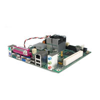
INTEL BLKD945GCLF - MB 533FSB DDR2 667 533 Aud+Vdo+Lan mATX Manuals
Manuals and User Guides for INTEL BLKD945GCLF - MB 533FSB DDR2 667 533 Aud+Vdo+Lan mATX. We have
2
INTEL BLKD945GCLF - MB 533FSB DDR2 667 533 Aud+Vdo+Lan mATX manuals available for free PDF download: Technical Product Specification, Product Manual
Intel BLKD945GCLF - MB 533FSB DDR2 667 533 Aud+Vdo+Lan mATX Technical Product Specification (84 pages)
Product Specification
Brand:
Intel
| Category:
Motherboard
| Size: 2 MB
Table of Contents
Revision History
2
Intended Audience
3
What this Document Contains
3
Table of Contents
5
1 Product Description
9
Overview
10
Feature Summary
10
Table 1. Feature Summary
10
Product Description
11
Board Layout
12
Figure 1. Major Board Components
12
Table 2. Board Components Shown in Figure 1
13
Block Diagram
14
Figure 2. Block Diagram
14
Legacy Considerations
15
Online Support
15
Processor
15
System Memory
16
Table 3. Supported Memory Configurations
16
Intel ® 945GC Chipset
17
Intel 945GC Graphics Subsystem
17
Configuration Modes
18
Usb
19
IDE Support
20
Serial Ata Interfaces
20
Real-Time Clock Subsystem
21
Legacy I/O Controller
22
Serial Port
22
Parallel Port
22
Keyboard and Mouse Interface
22
Audio Subsystem
23
Table 4. Audio Jack Retasking Support
23
Audio Connectors and Headers
24
Audio Subsystem Software
24
Figure 3. Back Panel Audio Connectors
24
1.10 LAN Subsystem
25
LAN Subsystem Software
25
RJ-45 LAN Connector with Integrated Leds
26
Figure 4. LAN Connector LED Locations
26
Table 5. LAN Connector LED States
26
1.11 Hardware Management Subsystem
27
Hardware Monitoring
27
Thermal Monitoring
28
Figure 5. Thermal Sensors and Fan Headers
28
1.12 Power Management
29
Acpi
29
Table 6. Effects of Pressing the Power Switch
29
Table 7. Power States and Targeted System Power
30
Table 8. Wake-Up Devices and Events
31
Hardware Support
32
Fan Headers
33
Lan Wake Capabilities
33
Instantly Available Pc Technology
34
Wake from Usb
35
Energy Star
36
Figure 6. Location of the Standby Power Indicator LED
36
2 Technical Reference
37
Memory Map
37
Addressable Memory
37
What this Chapter Contains 2.1 Memory Map
37
Figure 7. Detailed System Memory Address Map
38
Table 9. System Memory Map
39
Connectors and Headers
40
Back Panel Connectors
41
Figure 8. Back Panel Connectors
41
Component-Side Connectors and Headers
42
Figure 9. Component-Side Connectors and Headers
42
Table 10. Component-Side Connectors and Headers Shown in Figure 9
43
Table 11. Front Panel Audio Header
44
Table 12. Serial ATA Connectors
44
Table 13. Rear Chassis (3-Pin) Fan Header
44
Table 14. GMCH (3-Pin) Fan Header
44
Table 15. Main Power Connector
45
Table 16. ATX12V Power Connector
45
Figure 10. Connection Diagram for Front Panel Header
46
Table 17. Front Panel Header
46
Table 18. States for a One-Color Power LED
47
Table 19. States for a Two-Color Power LED
47
Figure 11. Connection Diagram for Front Panel USB Headers
48
Jumper Block
49
Figure 12. Location of the Jumper Block
49
Table 20. BIOS Setup Configuration Jumper Settings
49
Mechanical Considerations
50
Form Factor
50
Figure 13. Board Dimensions
50
Electrical Considerations
51
Power Supply Considerations
51
Fan Header Current Capability
51
Table 21. Recommended Power Supply Current Values
51
Table 22. Fan Header Current Capability
51
Add-In Board Considerations
52
Thermal Considerations
52
Figure 14. Localized High Temperature Zones
53
Table 23. Thermal Considerations for Components
53
Reliability
54
Environmental
54
Table 24. Desktop Board D945GCLF Environmental Specifications
54
What this Chapter Contains
55
What this Chapter Contains 3.1 Introduction
55
BIOS Flash Memory Organization
56
Resource Configuration
56
PCI* Autoconfiguration
56
Table 25. BIOS Setup Program Menu Bar
56
Table 26. BIOS Setup Program Function Keys
56
System Management BIOS (SMBIOS)
57
Legacy USB Support
58
BIOS Updates
59
Language Support
59
Custom Splash Screen
59
BIOS Recovery
60
Table 27. Acceptable Drives/Media Types for BIOS Recovery
60
Boot Options
61
CD-ROM Boot
61
Network Boot
61
Booting Without Attached Devices
61
Changing the Default Boot Device During POST
61
Table 28. Boot Device Menu Options
61
Adjusting Boot Speed
62
Peripheral Selection and Configuration
62
BIOS Boot Optimizations
62
3.10 BIOS Security Features
63
Table 29. Supervisor and User Password Functions
63
3 Overview of BIOS Features
55
Introduction
55
4 Error Messages and Beep Codes
65
BIOS Front-Panel Power LED Codes
65
Table 30. Front-Panel Power LED Blink Codes
65
BIOS Beep Codes
66
BIOS Error Messages
66
Beep Codes
66
Table 32. BIOS Error Messages
66
Port 80H POST Codes
67
Table 33. Port 80H POST Code Ranges
67
Port 80H POST Codes
68
Table 35. Typical Port 80H POST Sequence
71
5 Regulatory Compliance and Battery Disposal Information
73
Regulatory Compliance
73
Safety Standards
73
Table 36. Safety Standards
73
European Union Declaration of Conformity Statement
74
Product Ecology Statements
75
Disposal Considerations
75
Recycling Considerations
75
Lead Free Desktop Board
77
Table 37. Lead-Free Board Markings
78
EMC Regulations
79
Product Certification Markings (Board Level)
80
Product Certification Markings
80
Table 39. Product Certification Markings
80
Battery Disposal Information
81
Advertisement
INTEL BLKD945GCLF - MB 533FSB DDR2 667 533 Aud+Vdo+Lan mATX Product Manual (56 pages)
Brand:
INTEL
| Category:
Motherboard
| Size: 3 MB
Table of Contents
Fcc Declaration of Conformity
2
Revision History
2
Document Organization
3
Intended Audience
3
Table of Contents
5
Desktop Board Features
9
Desktop Board Components
10
Figures
10
Intel Desktop Board D945GCLF Components
10
Processor
12
Main Memory
12
Intel 945GC Express Chipset
13
Onboard Audio Subsystem
13
Input/Output (I/O) Controller
14
Back Panel Audio Connectors
14
LAN Subsystem
15
LAN Status Leds
15
LAN Subsystem Software
15
Hi-Speed USB 2.0 Support
16
Enhanced IDE Interface
16
Serial ATA
16
Expandability
16
Bios
17
IDE Auto Configuration
17
PCI Auto Configuration
17
Security Passwords
17
Power Management Features
18
Acpi
18
Fan Headers
18
Hardware Support
18
Power Connectors
18
+5 V Standby Power Indicator LED
19
Location of the Standby Power Indicator
19
LAN Wake Capabilities
20
Wake from USB
20
Wake from PS/2 Keyboard/Mouse
20
PME# Wakeup Support
20
Battery
20
Real-Time Clock
20
Installing and Replacing Desktop Board Components
21
Before You Begin
21
Installation Precautions
22
Prevent Power Supply Overload
22
Observe Safety and Regulatory Requirements
22
Installing the I/O Shield
23
Installing and Removing the Desktop Board
24
Desktop Board D945GCLF Mounting Screw Holes
24
Installing and Removing Memory
25
Installing Dimms
25
Use DDR2 Dimms
25
Removing Dimms
27
Connecting the IDE Cable
27
Connecting the IDE Cable
28
Connecting the Serial ATA (SATA) Cable
29
Connecting the Serial ATA Cable
29
Connecting Internal Headers
30
Connecting the Hi-Speed USB 2.0 Header
31
Front Panel HD Audio Header
31
Front Panel Audio Header Signal Names for Intel High Definition Audio
31
Hi-Speed USB 2.0 Header Signal Names
31
Connecting to the Front Panel Header
32
Connecting a Chassis Fan
32
Location of the Chassis Fan Header
32
Front Panel Header Signal Names
32
Connecting Power Supply Cables
33
Setting the BIOS Configuration Jumper
34
BIOS Configuration Jumper Block
34
Clearing Passwords
35
Jumper Settings for the BIOS Setup Program Modes
35
Replacing the Battery
36
Removing the Battery
40
Updating the BIOS
41
Updating the BIOS with the Intel Express BIOS Update Utility
41
Updating the BIOS with the Iflash Memory Update Utility
41
Obtaining the BIOS Update File
41
Updating the BIOS with the Iflash Memory Update Utility
42
Recovering the BIOS
42
A BIOS Error Messages
43
BIOS Front-Panel Power LED Codes
43
BIOS Beep Codes
43
BIOS Front-Panel Power LED Blink Codes
43
BIOS Error Messages
44
B Regulatory Compliance
45
Safety Standards
45
Place Battery Marking
45
European Union Declaration of Conformity Statement
46
Product Ecology Statements
47
Recycling Considerations
47
Lead-Free 2Li/Pb-Free 2LI Board
50
Lead-Free Second Level Interconnect Marks
50
Restriction of Hazardous Substances (Rohs)
51
China Rohs
51
European Union Rohs
51
Desktop Board D945GCLF China Rohs Material Self Declaration Table
52
EMC Regulations
53
Ensure Electromagnetic Compatibility (EMC) Compliance
54
Product Certifications
55
Board-Level Certification Markings
55
Product Certification Markings
55
Chassis and Component Certifications
56
Advertisement
Related Products
Intel BLKD945GCCR
Intel BLKD945GCCRL
Intel BLKD945GCLF2
Intel BLKD945GCLF2D
Intel BLKD945GCNL
Intel BLKD945GCPE - LGA775 1066FSB 2DDR2 2GB Audio Video Lan mATX 10Pack Motherboard
Intel BLKD945GNTL - LGA775 1066 800FSB 4DDR2 A/V Lan SATA ATX 10Pack Motherboard
Intel BLKD945GTPLKR
Intel BLKD945GTPL
Intel BLKD945GSEJT
INTEL Categories
Motherboard
Computer Hardware
Server
Desktop
Server Board
More INTEL Manuals
Login
Sign In
OR
Sign in with Facebook
Sign in with Google
Upload manual
Upload from disk
Upload from URL