Sign In
Upload
Manuals
Brands
IFR Manuals
Receiver
NAV-402AP-3
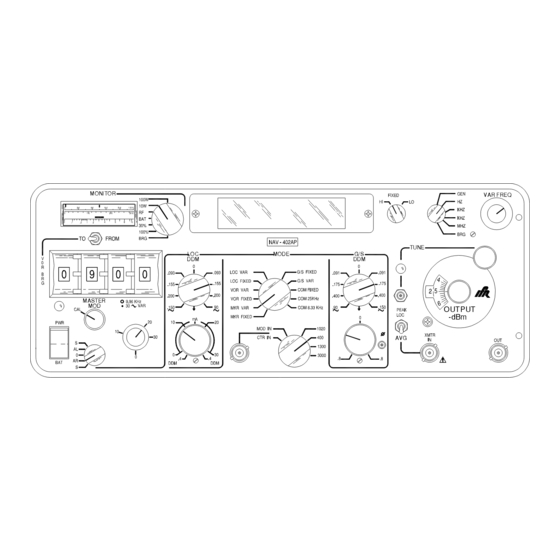
IFR NAV-402AP-3 Manuals
Manuals and User Guides for IFR NAV-402AP-3. We have
1
IFR NAV-402AP-3 manual available for free PDF download: Operation Manual
IFR NAV-402AP-3 Operation Manual (70 pages)
RAMP TEST SET
Brand:
IFR
| Category:
Receiver
| Size: 0.48 MB
Table of Contents
Table of Contents
14
Table of Contents
18
Sectio N 1 - Descriptio N
20
General Description and Capabilities
20
Description
20
Functional Capabilities
20
Sectio N 2 - O Peratio N
22
Installation
22
Battery Charging
22
Battery Operation
22
Complying with Instr Uctions
22
General
22
Grounding Power Cord
22
O Per Ating Safety
22
Safety Precautions
22
AC Power Requir Ements
23
Battery Recharging
23
CAUTION and WARNING Labels
23
Fcc Requirements
23
Specified Fuse Ratings
23
Bench Operation
24
External Cleaning
24
Controls, Connectors and Indicators
26
Table of Contents
27
Front Panel
28
MONITOR Meter
31
90/150 Hz VAR PHASE (Φ) Switch
32
G/S CENTER Adjust
32
G/S VAR DDM Control
32
LOC CENTER Adjust
32
MOD IN/EXT FREQ CTR in Connector
32
TONE SELECT Switch
32
30 Hz VAR LEVEL Control
33
Khz REF LEVEL Control
33
LOC DDM SWEEP Switch
33
LOC VAR DDM/DDM SWEEP AMPLITUDE Control
33
PWR/BAT Switch
33
Fuses
34
MASTER MOD LEVEL Control
34
NAV TONE out Connector
34
POWER on Indicator
34
PWR MON DEMOD Connector
34
Rear Panel
34
SIG GEN DEMOD Connector
34
VOLTAGE SELECT Switch
34
VOR BRG SELECT Switches
34
VOR BRG TO/FROM Switch
34
General Operating Procedures
35
Controls, Connectors and Indicators
35
General
35
Operation Cautions
35
Ramp Operation
35
Signals Simulated
35
Battery Parameters
36
Bench Operation
36
Counter Operation
36
Operate Loc and G/Ssimultaneo Usly
36
Marker Operation (Typical Control Settings)
37
COUNTER MODE Switch
38
CRYSTAL HI/LO Switch
38
FINE TUNE Switch
38
FREQUENCY MODE Switch
38
Khz REF LEVEL Control
38
VO R O Per Ation ( Typical Contr Ol Settings)
38
Localizer O Per Ation ( Typical Contr Ol Settings)
39
Control
40
G Lide Slope O Per Ation ( Typical Contr Ol Settings)
40
G/S DDM Control
40
Communication O Per Ation ( Receiver Tests) ( Typical Contr Ol Settings)
41
MASTER MOD LEVEL Control
41
MOD IN/EXT FREQ CTR in Connector
41
MONITOR Meter
41
MONITOR METER FUNCTION Switch
41
OUTPUT ATTENUATOR Control
41
PWR/BAT Switch
41
Communication O Per Ation ( Tr Ansmitter Tests) ( Typical Contr Ol Settings)
42
Cor R Espondence Char T for Decibels, Volts and Watts
44
Cor R Espondence Char T for 90 Hz and 150 Hz Tones ( lo C)
46
Section 3 - Specifications
47
NAV- 402AP Specifications
47
RF O Utput
47
Marker Mode
48
VO R Mode
49
G /S Mode
51
CO M Mode
52
External Freq Uency Counter
53
Batter y Level Monitor
54
Battery
54
Bearing Monitor
54
Power Meter
54
AC Power
55
Envir Onmental
55
VO R Bear Ing Select Switches
56
90 Hz and 150 Hz Tones Var Iable Phase Relationships
57
Section 4 - Shipping
59
Shipping Test Sets
59
Information
59
Repacking Procedure
59
Section 5 - Storage
61
Storing Test Sets
61
Advertisement
Advertisement
Related Products
IFR NAVAIR NAV-750
IFR NAVAIR NAV-750A
IFR NAVAIR NAV-750B
IFR Categories
Measuring Instruments
Inverter
Test Equipment
Service Equipment
Monitor
More IFR Manuals
Login
Sign In
OR
Sign in with Facebook
Sign in with Google
Upload manual
Upload from disk
Upload from URL