Sign In
Upload
Manuals
Brands
IBM Manuals
Storage
StorVize V7000 Gen2
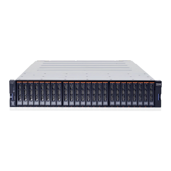
IBM StorVize V7000 Gen2 Manuals
Manuals and User Guides for IBM StorVize V7000 Gen2. We have
1
IBM StorVize V7000 Gen2 manual available for free PDF download: Quick Installation Manual
IBM StorVize V7000 Gen2 Quick Installation Manual (188 pages)
Brand:
IBM
| Category:
Storage
| Size: 34.63 MB
Table of Contents
Table of Contents
3
Figures
5
Tables
7
Safety and Environmental Notices
9
Safety Notices and Labels
9
Caution Notices for the Storwize V7000
10
Danger Notices for Storwize V7000
14
Special Caution and Safety Notices
17
General Safety
17
Handling Static-Sensitive Devices
18
Environmental Notices
18
About this Guide
19
Storwize V7000 Library and Related Publications
19
IBM Websites for Help, Services, and Information
19
Who Should Use this Guide
19
IBM Publications Center
20
IBM Documentation and Related Websites
20
How to Get Information, Help, and Technical Assistance
21
IBM Websites for Help, Services, and Information
21
Related Websites
21
Sending Your Comments
21
Chapter 1. Before You Begin the Installation
25
Enclosure
26
V7000
26
Support Rails
26
Steps for Different Installation Scenarios
26
Reviewing Your Packing Slip
29
Identify the Hardware Components
30
Rear View of a Storwize V7000 Control Enclosure
30
Data Ports in the Rear of the Storwize V7000
31
Control Enclosure Support Rails of a Storwize
32
Rear View of a Storwize V7000 Expansion
32
Expansion Enclosure
32
Identifying Storwize V7000 2076-624 Node Canisters
33
SAS Ports and Leds in Rear View of a Storwize
33
Expansion Enclosure Support Rails on Storwize
33
Verify Environmental Requirements
34
Release Handle Serial Label
34
Review Enclosure Location Guidelines
35
Chapter 2. Installing the Storwize V7000 Gen2 and Storwize V7000 Gen2+ Hardware
37
Installing Support Rails for the Storwize V7000 Gen2 and Storwize V7000 Gen2+ Control Enclosure
37
Control Enclosure Support Rails
37
Installing the Rail Spring
38
Hole Locations in the Front of the Rack
39
Selecting Bracket Pins for Your Rack
39
Opening the Hinge Brackets
40
Closing the Hinge Brackets
40
Installing Support Rails for Storwize V7000 Gen2 and Storwize V7000 Gen2+ Expansion Enclosures
41
Expansion Enclosure Support Rails
41
Installing the Rail Spring
42
Hole Locations in the Front of the Rack
43
Selecting Bracket Pins for Your Rack
43
Opening the Hinge Brackets
44
Closing the Hinge Brackets
44
Installing the Enclosures
45
Removing Enclosure End Caps
45
Inserting the Enclosure
46
The Enclosure
46
Connecting SAS Cables to Expansion Enclosures
47
Reinstalling Enclosure End Caps
47
Connecting the SAS Cables
48
SAS Cabling Guidelines
49
SAS Cable Connectors
49
Installing an Optional 5U SAS Expansion Enclosure
50
Connecting the SAS Cables
50
Safety Notices and Considerations: 2076-92F
51
Weight Considerations: 2076-92F
57
Weight of Expansion Enclosure Parts
58
Weight of Expansion Enclosure Drives
59
Weight of an Enclosure with 92 SAS Drives
60
Identify the Hardware Components: 2076-92F
62
Features on the Front of the 2076-92F
62
Front Fascia of the 2076-92F Expansion
63
Features on the Rear of the 2076-92F Expansion
63
F Support Rails
64
Unpacking and Installing the Enclosure: 2076-92F
65
Tray Containing Expansion Enclosure Parts
66
Packaging Materials
67
Removing the Top Cover: 2076-92F
68
Packaging for Fascia
68
Releasing the 2076-92F Cover
69
Removing the 2076-92F Cover
69
Installing or Replacing the Support Rails: 2076-92F
70
Detaching the Inner Rail Section
71
Screw Locations to Attach the Inner Rail to the
71
Attaching the Inner Rail Section to the
72
Installing the Rail Assembly to the Rack Frame
72
Installing or Replacing an Expansion Enclosure in a Rack: 2076-92F
73
Example of Required Rack Space
73
Example Installation of the Enclosure in the
79
Replacing the 2076-92F Enclosure in the Rack
80
Installing or Replacing an Expansion Canister: 2076-92F
81
Removing or Moving the Cable-Management Arm: 2076-92F
82
Install the Expansion Canister
82
Upper and Lower Cable-Management Arms
83
Connectors for the Upper Cable Management
84
Components of the Lower CMA Assembly
85
Upper and Lower CMA Assemblies Moved
86
Lower CMA Assembly Moved
86
Installing or Replacing the Cable-Management Arm: 2076-92F
87
Release the Upper CMA Assembly
87
Release the Lower CMA Assembly
87
Upper and Lower Cable-Management Arms
88
Connectors for the Cable Management Arm
89
Install the Inner Connector of the Upper CMA
89
Install the Inner Connector of the Upper CMA
90
Attach the Support Rail Connector of the Upper
90
Comparing the Location of the Components of
91
Installing or Replacing the Top Cover: 2076-92F
92
Aligning the 2076-92F Top Cover
92
Installing or Replacing a Drive: 2076-92F
93
Replacing the 2076-92F Top Cover
93
Locking the Top Cover
93
Drive Assembly
94
Drive Locations in a 2076-92F Expansion
95
Correct Drive Installation
95
Incorrect Drive Installation
96
Installing or Replacing a Secondary Expander Module: 2076-92F
98
Location of Secondary Expander Modules
99
Leds on a Secondary Expansion Module
100
Installing or Replacing the Fascia: 2076-92F
101
Replace the Secondary Expander Module
101
Fascia Components on the Expansion Enclosure
102
Installing or Replacing a Power Supply: 2076-92F
103
Preparing to Install the Power Supply
104
Install the Power Supply
105
Removing the Fascia: 2076-92F
106
Power Supply Indicators
106
Fascia Components on the Expansion Enclosure
107
Remove Fascia Components from the Expansion Enclosure
108
Removing and Installing a SAS Cable: 2076-92F
109
Fascia Removed from the Psus
109
Correct Orientation for SAS Cable Connectors
110
Example of SAS Cables Routed through the Cable Management Arms
111
Installing or Replacing a Fan Module: 2076-92F
112
SAS Cable Correctly Inserted into the SAS Port
112
Installing or Replacing a Fan Interface Board: 2076-92F
113
Fan Module Orientation
113
Replace Fan Module
113
FIB Parts for the Chassis
114
Insert the New FIB in the Chassis
115
Secure the FIB to the Drive Board
115
Removing an Expansion Enclosure from a Rack: 2076-92F
116
Replace the FIB Cover
116
Removing the 2076-92F Enclosure from the
123
Removing a Power Supply: 2076-92F
124
Releasing the Power Supply Handles
125
Removing a Drive: 2076-92F
126
Removed Power Supply
126
Drive Assembly
127
Drive Locations in a 2076-92F Expansion
128
Removing a Secondary Expander Module: 2076-92F
129
Replace the Drive
129
Remove the Drive Assembly
129
Location of Secondary Expander Modules
131
Location of Leds on the Secondary Expander
131
Remove the Secondary Expander Module
132
Removing an Expansion Canister: 2076-92F
133
Secondary Expander Module Connectors
133
Secondary Expander Module Removed from
133
Removing a Fan Module: 2076-92F
135
Removing the Expansion Canister
135
Fan Module LED
136
Fan Module Release Tab
136
Removing a Fan Interface Board: 2076-92F
137
Remove Fan Module
137
Fan Module LED
138
Location of the FIB Cover
138
Loosen the FIB Screws
139
Remove the FIB from the Chassis
139
Replacing an Enclosure: 2076-92F
140
FIB Parts Removed from the Chassis
140
Removing the Display Panel Assembly: 2076-92F
142
Removing the Display Panel Assembly
143
Installing or Replacing the Display Panel Assembly: 2076-92F
144
Display Panel Assembly
144
Display Panel Assembly
146
Removing the Support Rails: 2076-92F
147
Installing the Display Panel Assembly
147
Remove the Rail Assembly from the Front Frame Bracket
147
Connecting the Optional 2076-92F SAS Expansion Enclosures
148
Remove the Rail Assembly from the Rear Frame
148
SAS Cable Connector Orientation
148
Connecting the SAS Cables
150
Powering on the Expansion Enclosure: 2076-92F
151
SAS Port Orientation on Expansion Enclosures
151
Examples of Supported SAS Chain
151
Features on the Front of the 2076-92F
152
Power Cable Connections on the Back of the
153
Powering off the Expansion Enclosure: 2076-92F
154
Expansion Canister
154
Features on the Rear of the 2076-92F
154
Storwize V7000 2076-92F Expansion Enclosure Leds and Indicators
155
Leds on the Front of the Expansion Enclosure
156
Display Panel Leds
156
Leds on the Front of a Power Supply Unit
157
Power Supply Unit Leds
157
Leds on a Drive Assembly
158
LED Indicators on Drives
158
Leds on a Secondary Expansion Module
159
LED Indicators on Secondary Expansion
159
Leds on the Back of the Expansion Enclosure
160
Leds on the Back of the Expansion Canister
160
Connecting Ethernet Cables to Node Canisters
161
Expansion Canister and SAS Port Leds
161
Connecting Fibre Channel Cables to a 10 Gbps Iscsi-Fcoe 4-Port Host Interface Adapter
162
V7000 System
162
Connecting the Ethernet Cables
162
Connecting Fibre Channel Cables to a Fibre Channel Host Interface Adapter
163
Example Configuration with Ethernet Cables
163
Example Configuration with Two Fibre
163
Powering on the System
164
Example Configuration with Four Fibre
164
Expansion Canister
165
Node Canister Leds
165
Chapter 3. Configuring the System
167
Checking Your Web Browser Settings for the Management GUI
167
User Name and Password for System Initialization
170
Initializing the System by Using the Technician Port
170
Default User Name and Password for the
170
Adding an Expansion Enclosure to an Existing System
171
Storwize V7000 Technician Port
171
Adding a Control Enclosure to an Existing System
172
Appendix A. Accessibility Features for Storwize V7000
173
Appendix B. Where to Find the Statement of Limited Warranty
175
Notices
177
Trademarks
179
Homologation Statement
179
Electronic Emission Notices
179
Federal Communications Commission (FCC) Statement
179
Industry Canada Compliance Statement
180
Australia and New Zealand Class a Statement
180
European Union Electromagnetic Compatibility Directive
180
Germany Electromagnetic Compatibility Directive
180
People's Republic of China Class a Statement
181
Taiwan Class a Compliance Statement
182
Taiwan Contact Information
182
Japan Voluntary Control Council for Interference Class a Statement
182
Japan Electronics and Information Technology Industries Association Statement
182
Korean Electromagnetic Interference (EMI) Statement
183
Russia Electromagnetic Interference Class a Statement
183
Index
185
Advertisement
Advertisement
Related Products
IBM StorVize V7000 Gen2+
IBM SAN04B-R - System Storage Router
IBM SAN384B-2
IBM SAN384B
IBM SAN42B-R
IBM SAN384C-6
IBM SAN50C-R
IBM TotalStorage SAN256N Director 2045-N16
IBM SAN128B-7
IBM SAN768C-6
IBM Categories
Server
Desktop
Storage
Laptop
Monitor
More IBM Manuals
Login
Sign In
OR
Sign in with Facebook
Sign in with Google
Upload manual
Upload from disk
Upload from URL