IAI ELECYLINDER TB-03 Teaching Pendant Manuals
Manuals and User Guides for IAI ELECYLINDER TB-03 Teaching Pendant. We have 5 IAI ELECYLINDER TB-03 Teaching Pendant manuals available for free PDF download: Instruction Manual, First Step Manual

IAI ELECYLINDER TB-03 Instruction Manual (774 pages)
Program Controller Wired Link
Brand: IAI
|
Category: Controller
|
Size: 55 MB
Table of Contents
-
Safety Guide13
-
Introduction21
-
Back30
-
Cable Joint31
-
AC Adapter37
-
Rsel67
-
Xsel2-T/Tx68
-
Caution69
-
Program Mode99
-
Positioner Mode104
-
RSEL Controller108
-
Menu Selection135
-
Position Edit139
-
Basic Operation144
-
Teaching156
-
Teaching175
-
Teaching202
-
Program Edit229
-
Program: Clear262
-
Cautions283
-
Symbol Edit305
-
Parameter Edit315
-
Monitor325
-
Monitor Items325
-
Input Port326
-
Output Port329
-
Global Flag330
-
Global Variable331
-
Axis Status333
-
System Status338
-
Error List339
-
Pairing ID Clear355
-
Fan Replacement356
-
Grease Supply357
-
Controller363
-
Controller Items363
-
Software Reset366
-
Error Reset367
-
Memory Clear368
-
Global Variable369
-
Position Data370
-
Re-Connection384
-
Baud Rate Change385
-
Safety Velocity386
-
Time Setting391
-
Clear Pairid393
-
Basic Operation400
-
6-Axis Cartesian407
-
Wrist Unit408
-
Multi-Slider409
-
EC Jog Setting422
-
Brake Control428
-
Absolute Reset431
-
Synchro Axes483
-
Description602
-
Description625
-
Menu Selection630
-
Monitor632
-
Manual Mode649
-
Auto Servo off654
-
Operation Status657
-
I/O Signal657
-
Pressure Setting658
-
Alarm659
-
Manual Mode659
-
Edit Parameter665
-
Test Run668
-
I/O Test673
-
Alarm List674
-
ROBO PUMP Reset678
-
Other Setting680
-
Inquiry685
-
Easy Programming706
-
Data Backup711
-
Error Display743
-
Appendix761
-
Screenshot761
-
Teaching Update762
-
Troubleshooting766
-
Warranty767
-
Warranty Period767
-
Change History769
Advertisement

IAI ELECYLINDER TB-03 Instruction Manual (528 pages)
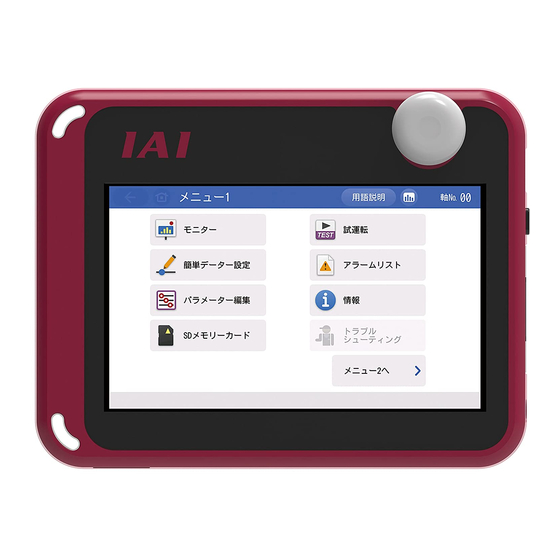
Touch Panel Teaching Pendant
Brand: IAI
|
Category: Telephone Accessories
|
Size: 33 MB
Table of Contents
-
Safety Guide13
-
Back31
-
Cable Joint32
-
AC Adapter38
-
Feature42
-
Joining Unit52
-
Damaged)56
-
Connection59
-
Cb-Adtb-Pwtb63
-
Easy Setting81
-
Monitor83
-
Position Edit110
-
Position Data111
-
Basic Operation121
-
Parameter Edit125
-
Test Run127
-
I/O Test133
-
Alarm List135
-
Controller Reset136
-
Other Settings137
-
I/O Customizing139
-
Axis Name Edit147
-
LCD Check157
-
Data Backup162
-
Moving Distance170
-
Easy Programming176
-
Offboard Tuning184
-
Servo Monitor190
-
Trigger Setting195
-
Press Program200
-
SD Memory Card230
-
Operating Menu244
-
Initial Screen246
-
Initial Setting247
-
Menu Selection249
-
Monitor250
-
Information252
-
Alarm List254
-
Position Data257
-
Basic Operation261
-
Setting Item282
-
Basic Operation286
-
Parameters291
-
System Password)291
-
Data Backup313
-
Operating Menu320
-
Initial Screen322
-
Initial Setting323
-
Initial Setting326
-
Position Setting331
-
Test Run351
-
Information353
-
Monitor378
-
Operating Menu381
-
Initial Screen383
-
Menu Selection385
-
Monitor387
-
Manual Mode410
-
Auto Servo off416
-
Operation Status419
-
I/O Signal419
-
Pressure Setting420
-
Alarm421
-
Manual Mode421
-
Parameter Edit426
-
Test Run428
-
I/O Test433
-
Alarm List435
-
Controller Reset436
-
ROBO PUMP Reset437
-
Other Setting438
-
Axis Name Edit443
-
Data Backup455
-
Easy Programming461
-
Network Setting468
-
Monitor Menu476
-
Data Monitor476
-
Alarm List478
-
SD Memory Card479
-
Clock Setting482
-
Guideline483
-
Operation484
-
Initial Screen484
-
Connection485
-
ADTB Data Backup491
-
Error Display497
-
Appendix505
-
Screenshot505
-
Teaching Update506
-
Troubleshooting520
-
Warranty521
-
Warranty Period521
-
Change History523

IAI ELECYLINDER TB-03 Instruction Manual (114 pages)
Touch Panel Teaching Pendant
Brand: IAI
|
Category: Touch Panel
|
Size: 7 MB
Table of Contents
-
-
AC Adapter32
-
Connection
39 -
-
Monitor53
-
Test Run67
-
Alarm List71
-
Data Backup88
-
Appendix
105
Advertisement

IAI ELECYLINDER TB-03 First Step Manual (5 pages)
Touch Panel Teaching Pendant , ELECYLINDER Wireless Link Program Controller Wired Link, Position Controller ELECYLINDER Wired Link
Brand: IAI
|
Category: Telephone Accessories
|
Size: 2 MB

IAI ELECYLINDER TB-03 First Step Manual (4 pages)
Touch Panel Teaching Pendant
Brand: IAI
|
Category: Touch Panel
|
Size: 1 MB
Advertisement