Sign In
Upload
Manuals
Brands
IAI Manuals
Robotics
TTA Series
IAI TTA Series Tabletop Robot Manuals
Manuals and User Guides for IAI TTA Series Tabletop Robot. We have
2
IAI TTA Series Tabletop Robot manuals available for free PDF download: Instruction Manual
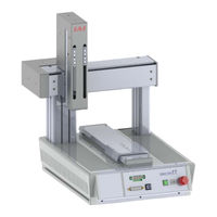
IAI TTA Series Instruction Manual (378 pages)
Tabletop Robot
Brand:
IAI
| Category:
Robotics
| Size: 24.25 MB
Table of Contents
Table of Contents
5
Name and Function of each Part
26
Chapter 1 Specifications Check
43
Product Check
43
Parts
43
Instruction Manuals Related to this Product, Which Are Contained in the Instruction Manual (DVD)
44
How to Read the Model Plate
44
How to Read the Model
45
Model Codes for Option of Y-Axis Mount Position Change
47
Model Code for ZR Axis Front-Back Direction Position Change Option
48
Mechanical Specifications
49
Speed
49
Work Moving Type Pulse Motor Specifications
49
Work Fixing Type Pulse Motor Specifications
49
Work Moving Type Servo Motor Low Lead Specifications
49
Work Moving Type Servo Motor High Lead Specification
49
Work Fixing Type Servo Motor Low Lead Specifications
50
Work Fixing Type Servo Motor High Lead Specification
50
Max. Speed, Max. Acceleration Speed and Transportable Mass
51
Work Moving Type Pulse Motor Specifications
51
Work Fixing Type Pulse Motor Specifications
51
Work Moving Type Servo Motor Low Lead Specifications
52
Work Moving Type Servo Motor High Lead Specification
52
Work Fixing Type Servo Motor Low Lead Specifications
53
Work Fixing Type Servo Motor High Lead Specifications
53
Driving System and Position Detector
54
Pulse Motor Standard Specifications
54
Pulse Motor High Resolution Specifications
54
Servo Motor Low Lead Specifications
54
Servo Motor High Lead Specifications
54
Positioning Repeatability, Lost Motion (Note 1)
55
Pulse Motor Standard Specifications
55
Pulse Motor High Resolution Specifications
55
Servo Motor Low Lead Specifications
55
Servo Motor High Lead Specifications
55
Relation between Current Limit Value and Pressing Force
56
Pulse Motor Specifications
56
Servo Motor Specifications
58
Allowable Moment for Actuator
59
Work Moving Type Pulse Motor Specifications
59
Work Fixing Type Pulse Motor Specifications
60
Work Moving Type Servo Motor Specifications
61
Work Fixing Type Servo Motor Specifications
62
Ma Direction Moment Offset Datum Position and the Moment Direction of each Axis
63
Duty of Continuous Operation
65
Electrical Specifications
70
Protection Circuit
72
Selection of Circuit Breaker
72
Selection of Leakage Breaker
73
Standard I/O Input and Output Interface
74
Standard I/O Connector Pin Assignment
75
Extension I/O Input and Output Interface
76
Extension I/O Connector Pin Assignment
77
Table for I/O Assignment
78
Specifications for Service Power Supply Output
81
Options
82
X, y and Z-Axes Options
82
Home-Position Check Sensor (Model: HS)
82
Reversed-Home Specification (Model: NM)
82
Brake Specification (Model: B)
82
With Cover Specification (Dedicated for 4-Axis Type) (Model: CO)
82
Equipment Options
82
Y Change in Y-Axis Mount Position (H1, H2, F1 and F2)
82
Main-Unit Bracket-Equipped Type (Model: FT4, FT6)
82
Support Added for 2020 Type (Model: AP)
82
Chapter 2 Installation
83
Transportation
83
Installation and Storage • Preservation Environment
83
Installation Environment
83
Storage • Preservation Environment
83
How to Install
84
Installation Orientation
84
How to Fix Unit
85
Work Moving Type
85
Work Fixing Type
86
Attachment of the Transported Object
87
Loadable Weight on Table
88
How to Attach Supportive Tools
89
Procedures to Detach Operation Part
90
Chapter 3 Wiring
93
Wiring Diagram
93
Power Supply, Emergency Stop Circuit and Enable Circuit
94
Pulse Motor Type
94
Internal Circuit Composition
94
Example for Composition of Emergency Stop and Enable Circuits
96
AC Servo Motor Type
101
Internal Circuit Composition
101
Example for Composition of Emergency Stop and Enable Circuits
103
Safety Circuit Timing Charts for TTA (Pulse Motor, Servo Motor)
108
IO Circuit
115
Input and Output Ports Assignment Specification
115
I/O Assignment Parameter List
118
Example for Parameter Settings at Delivery
119
Standard I/O
121
When Service Power Supply Switch Is on (Internal Power Source)
121
When Service Power Supply Switch Is on (Internal Power Source)
122
When Service Power Supply Switch Is off (External Power Source)
123
Extension I/O
124
Wiring Method
125
Wiring on AC Inlet for Power Supply
125
Wiring for the Teaching Tool
125
RS232C Interface
126
USB Interface
127
Wiring of System I/O
128
Wiring for PIO
129
IO Cable Layout
129
IO Replacement Cable Layout
130
Grounding
131
Wiring for SIO Module Communication Cable
132
SIO Module 485 Communication Cable (One End with Bare Cut Without Connectors with no Terminal Finishing)
132
SIO Module 485 Communication Cable (One End with Bare Cut Without Connectors with Terminal Finishing)
132
Connectors
133
SIO Module 232C Communication Cable (One End with Bare Cut Without Connectors)
133
Chapter 4 Operation
135
Types of Operations
135
Starting the Controller
136
Power Supply and Cutoff
136
Power Supply Sequence
136
Power Cutoff Sequence
136
Panel Window Display
137
Program Operation
139
Auto Start Upon Power on
139
Starting a Program by Specifying Its Program Number
141
Receiving and Forwarding of I/O Signals Necessary for Operation
143
Position Table and Program Creation and Writing
146
How to Use Internal DIO
147
Internal DI and Dedicated Functions
147
7-Segment Display by User SEL Program
148
Standard Interface
151
Payload Adjusted for Setting Values
155
Work Moving Type Pulse Motor Specifications
156
Work Fixing Type Pulse Motor Specifications
157
Work Moving Type Servo Motor Low Lead Specifications
158
Work Moving Type Servo Motor High Lead Specification
160
Work Fixing Type Servo Motor Low Lead Specifications
161
Work Fixing Type Servo Motor High Lead Specification
163
Chapter 5 List of Parameters
165
I/O Parameters
166
All Axes Common Parameters
187
Axis-Specific Parameters
191
Driver Card Parameters
197
Encoder Parameters
202
I/O-Slot Card Parameters
204
Other Parameters
208
Parameters for Linear / Rotation Controls
213
Chapter 6 Error List
214
Error Level Control
214
Error List (MAIN Application)
217
Error List (MAIN Core)
250
Chapter 7 Appendix
253
Work and Tool Coordinate System Features for Linear Axis
253
Coordinates for Coordinate System Definition Unit
254
Each Axis System
255
Base Coordinate System
256
Work Coordinate System
258
Tool Coordinate System
263
Setting of Parameters
267
Caution Note
270
Limitation in Coordinate System Constructing Axes
270
Note for Other Caution
271
Extension SIO Features
272
Specification
272
Functions
272
Caution
273
Parameter Setting
274
Example of Use
279
Chapter 8 Maintenance and Inspection
281
Inspection Items and Schedule
281
External Visual Inspection
281
Internal Visual Inspection
281
Cleaning
281
Grease Supply
282
Grease to Apply
282
Period of Time to Supply Grease
282
How to Supply the Grease
283
Replacement of Timing Belt
291
Inspecting the Belt
291
Applicable Belt
291
Period of Time for Fan Unit Replacement
311
Chapter 9 External Dimensions
313
Servo Motor Type, Pulse Motor Type (Battery-Less Absolute Specification)
313
Work Moving Type
313
Two-Axis: X & Y-Axes 200Mm Stroke
313
Two-Axis: X & Y-Axes 300Mm Stroke
314
Two-Axis: X & Y-Axes 400Mm Stroke
315
Two-Axis: X & Y-Axes 500Mm Stroke
316
Three-Axis: X & Y-Axes 200Mm Stroke, Z-Axis 100Mm/150Mm Stroke
317
Three-Axis: X & Y-Axes 300Mm Stroke, Z-Axis 100Mm/150Mm Stroke
318
Three-Axis: X & Y-Axes 400Mm Stroke, Z-Axis 100Mm/150Mm Stroke
319
Three-Axis: X & Y-Axes 500Mm Stroke, Z-Axis 100Mm/150Mm Stroke
320
Four-Axis: X & Y-Axes 200Mm Stroke, Z-Axis 100Mm/150Mm Stroke
321
Four-Axis: X & Y-Axes 300Mm Stroke, Z-Axis 100Mm/150Mm Stroke
322
Four-Axis: X & Y-Axes 400Mm Stroke, Z-Axis 100Mm/150Mm Stroke
323
Four-Axis: X & Y-Axes 500Mm Stroke, Z-Axis 100Mm/150Mm Stroke
324
Work Fixing Type
325
Two-Axis: X- Axis 200Mm Stroke, Y-Axis 150Mm Stroke
325
Two-Axis: X- Axis 300Mm Stroke, Y-Axis 250Mm Stroke
326
Two-Axis: X- Axis 400Mm Stroke, Y-Axis 350Mm Stroke
327
Two-Axis: X- Axis 500Mm Stroke, Y-Axis 450Mm Stroke
328
Three-Axis: X- Axis 200Mm Stroke, Y-Axis 150Mm Stroke, Z-Axis 100Mm/150Mm Stroke
329
Three-Axis: X- Axis 300Mm Stroke, Y-Axis 250Mm Stroke, Z-Axis 100Mm/150Mm Stroke
330
Three-Axis: X- Axis 400Mm Stroke, Y-Axis 350Mm Stroke, Z-Axis 100Mm/150Mm Stroke
331
Three-Axis: X- Axis 500Mm Stroke, Y-Axis 450Mm Stroke, Z-Axis 100Mm/150Mm Stroke
332
Four-Axis: X- Axis 300Mm Stroke, Y-Axis 250Mm Stroke, Z-Axis 100Mm/150Mm Stroke
333
Four-Axis: X- Axis 300Mm Stroke, Y-Axis 250Mm Stroke, Z-Axis 100Mm/150Mm Stroke
334
Four-Axis: X- Axis 400Mm Stroke, Y-Axis 350Mm Stroke, Z-Axis 100Mm/150Mm Stroke
335
Four-Axis: X- Axis 500Mm Stroke, Y-Axis 450Mm Stroke, Z-Axis 100Mm/150Mm Stroke
336
Pulse Motor Type (Incremental Specification)
337
Work Moving Type
337
Two-Axis: X & Y-Axes 200Mm Stroke
337
Two-Axis: X & Y-Axes 300Mm Stroke
338
Two-Axis: X & Y-Axes 400Mm Stroke
339
Two-Axis: X & Y-Axes 500Mm Stroke
340
Three-Axis: X & Y-Axes 200Mm Stroke, Z- Axis 100Mm/150Mm Stroke
341
Three-Axis: X & Y-Axes 300Mm Stroke, Z- Axis 100Mm/150Mm Stroke
342
Three-Axis: X & Y-Axes 400Mm Stroke, Z- Axis 100Mm/150Mm Stroke
343
Three-Axis: X & Y-Axes 500Mm Stroke, Z- Axis 100Mm/150Mm Stroke
344
Four-Axis: X & Y-Axes 200Mm Stroke, Z- Axis 100Mm/150Mm Stroke
345
Four-Axis: X & Y-Axes 300Mm Stroke, Z- Axis 100Mm/150Mm Stroke
346
Four-Axis: X & Y-Axes 400Mm Stroke, Z- Axis 100Mm/150Mm Stroke
347
Four-Axis: X & Y-Axes 500Mm Stroke,Z- Axis 100Mm/150Mm Stroke
348
Work Fixing Type
349
Two-Axis: X-Axis 200Mm Stroke, Y-Axis 150Mm Stroke
349
Two-Axis: X-Axis 300Mm Stroke, Y-Axis 550Mm Stroke
350
Two-Axis: X-Axis 400Mm Stroke, Y-Axis 350Mm Stroke
351
Two-Axis: X-Axis 500Mm Stroke, Y-Axis 450Mm Stroke
352
Three-Axis: X-Axis 200Mm Stroke, Y-Axis 150Mm Stroke, Z-Axis 100Mm/150Mm Stroke
353
Three-Axis: X-Axis 300Mm Stroke, Y-Axis 250Mm Stroke, Z-Axis 100Mm/150Mm Stroke
354
Three-Axis: X-Axis 400Mm Stroke, Y-Axis 350Mm Stroke, Z-Axis 100Mm/150Mm Stroke
355
Three-Axis: X-Axis 500Mm Stroke, Y-Axis 450Mm Stroke, Z-Axis 100Mm/150Mm Stroke
356
Four-Axis: X-Axis 200Mm Stroke, Y-Axis 150Mm Stroke, Z-Axis 100Mm/150Mm Stroke
357
Four-Axis: X-Axis 300Mm Stroke, Y-Axis 250Mm Stroke, Z-Axis 100Mm/150Mm Stroke
358
Four-Axis: X-Axis 400Mm Stroke, Y-Axis 350Mm Stroke, Z-Axis 100Mm/150Mm Stroke
359
Four-Axis: X-Axis 500Mm Stroke, Y-Axis 450Mm Stroke, Z-Axis 100Mm/150Mm Stroke
360
Work Moving Type
361
Option
361
Frame Option
362
Side Plate Option
363
Side Slot Option
364
Bracket-Equipped Option
365
Work Fixing Type
366
Frame Option
366
Side Slot Option
367
Chapter 10 Life
369
Chapter 11 Warranty
371
Warranty Period
371
Scope of the Warranty
371
Honoring the Warranty
371
Limited Liability
371
Conditions of Conformance with Applicable Standards/Regulations, Etc., and Applications
372
Other Items Excluded from Warranty
372
Change History
373
Advertisement
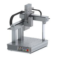
IAI TTA Series Instruction Manual (377 pages)
Tabletop Robot
Brand:
IAI
| Category:
Robotics
| Size: 33 MB
Table of Contents
Product Check
1
Basic Specifications
1
Optional Components
1
How to Read the Model
1
Names of the Parts
2
Installation Environment
2
Installation and Noise Elimination
2
Work Fixing Type Pulse Motor Type
2
Wiring Diagram
3
I/O Signal
3
Input and Output Type
3
Devicenet
4
CC-Link
4
Profibus-Dp
4
Ethernet/Ip
4
Troubleshooting
5
Tabletop Robot
6
Table of Contents
10
Safety Guide
16
Safety Precautions of Our Products
16
Alert Indication
22
Explanation of Caution Labels Attached on Devices
22
Caution on Handling
23
Rescue at Emergency
24
Rear Panel Side of Main Body
25
Front Panel Side of Main Body
25
Dimensions for Safety Protection Fence
26
Name and Function of each Part
31
Details of Front Panel
32
Brake Releasing Switch
32
Panel Window
33
Application Display Specifications
33
Operation Mode Switch
34
Emergency Stop Switch
34
Program Switch
34
Core Display Specifications
34
Function Switch
35
USB Connector
35
Teaching Tool Connector
35
How to Take off Front Panel
36
Details of Rear Panel
37
AC Inlet
37
Power Switch
37
Standard I/O Service Power Supply Connector
40
System I/O Connector
40
Motor Power Supply Connector
41
Pulse Motor Type
41
AC Servo Motor Type
41
Service Power Switch
41
About Coordinate System
42
Each Axis System
42
Base Coordinate System
43
Work Coordinate System
45
Tool Coordinate System
46
Specifications Check
48
Parts
48
Mechanical Specifications
54
Speed
54
Max. Speed, Max.acceleration Speed
56
Relation between Current Limit Value and Pressing Force
61
Pulse Motor Specifications
61
R-Axis
62
Servo Motor Specifications
63
Z-Axis
63
Current Limit Value
63
Allowable Moment for Actuator
64
Work Moving Type Pulse Motor Specifications
64
Work Fixing Type Pulse Motor Specifications
65
Work Moving Type Servo Motor Specifications
66
Work Fixing Type Servo Motor Specifications
67
Ma Direction Moment Offset Datum Position
68
Duty of Continuous Operation
70
How to Calculate Duty
70
How to Check Operation Pattern
70
Load Factor LF
70
Cycle Time Tc
71
Acceleration/Deceleration Time Ratio Tod
71
Duty
71
Electrical Specifications
75
Protection Circuit
77
Selection of Circuit Breaker
77
Selection of Leakage Breaker
78
Standard I/O Input and Output Interface
79
Standard I/O Connector Pin Assignment
80
Extension I/O Input and Output Interface
81
Extension I/O Connector Pin Assignment
82
Table for I/O Assignment
83
Specifications for Service Power Supply Output
85
Options
86
X, y and Z-Axes Options
86
Equipment Options
86
Installation
87
Transportation
87
How to Install
88
Installation Orientation
88
How to Fix Unit
89
Work Moving Type
89
Attachment of the Transported Object
91
Loadable Weight on Table
92
How to Attach Supportive Tools
93
Procedures to Detach Operation Part
94
Wiring
97
Power Supply, Emergency Stop Circuit and Enable Circuit
98
Global Specification
99
Internal Circuit Composition
105
Safety Circuit Timing Charts for TTA
112
Power on
112
Emergency Stop
113
Power on During Emergency Stop
114
Enable Input
115
System Shutdown Level Error
116
Cold Start Lever Error
117
Operation Cancellation Level Error
118
IO Circuit
119
Input and Output Ports Assignment Specification
119
I/O Assignment Parameter List
121
Standard I/O
124
PIO Connector
124
Extension I/O
127
Wiring Method
128
Wiring on AC Inlet for Power Supply
128
Wiring for the Teaching Tool
128
RS232C Interface
129
Terminal Assignments
129
USB Interface
130
USB/232 Switchover Circuit
130
Wiring for System I/O
131
Wiring for PIO
132
IO Cable Layout
132
IO Replacement Cable Layout
133
Grounding
134
Single-Phase
134
Wiring for SIO Module Communication Cable
135
Operation
137
Types of Operations
137
Teaching Tool
137
Starting the Controller
138
Power Supply and Cutoff
138
Power Supply Sequence
138
Power Cutoff Sequence
138
Panel Window Display
139
Program Operation
141
Auto Start Upon Power on
141
Starting a Program by Specifying Its Program Number
143
Receiving and Forwarding of I/O Signals Necessary for Operation
145
I/O Map
146
Position Table and Program Creation and Writing
148
How to Use Internal DIO
149
Internal DI and Dedicated Functions
149
7-Segment Display by User SEL Program
150
Standard Interface
153
Example for Assignment of Output Function Select
155
Example of Use
156
I/O Parameter Setting Value
156
Payload Adjusted for Setting Values
157
List of Parameters
166
I/O Parameters
167
Axis-Specific Parameters
192
Driver Card Parameters
198
Other Parameters
209
Work and Tool Coordinate System Features for Linear Axis
254
Coordinates for Coordinate System Definition Unit
255
Parameter Setting
275
Extension I/O Slot
275
How to Set Parameters
279
IAI Protocol Communication Individual Setting
279
Maintenance and Inspection
281
Inspection Items and Schedule
281
External Visual Inspection
281
Internal Visual Inspection
281
Grease Supply
282
Grease to Apply
282
Period of Time to Supply Grease
282
How to Supply the Grease
283
Replacement of Timing Belt
291
Inspecting the Belt
291
Applicable Belt
291
External Dimensions
312
Advertisement
Related Products
IAI TTA-C4
IAI TTA-A4
IAI TTA-A2
IAI TTA-C2
IAI TTA-A3
IAI TTA-C3
IAI tt
IAI TB-02
IAI ELECYLINDER TB-03
IAI TB-03-SCN-E-ENG
IAI Categories
Controller
Digital Camera
Security Camera
Gateway
Touch Panel
More IAI Manuals
Login
Sign In
OR
Sign in with Facebook
Sign in with Google
Upload manual
Upload from disk
Upload from URL