Sign In
Upload
Manuals
Brands
Hydac Manuals
Accessories
CS 2000 series
Hydac CS 2000 series Contamination Sensor Manuals
Manuals and User Guides for Hydac CS 2000 series Contamination Sensor. We have
1
Hydac CS 2000 series Contamination Sensor manual available for free PDF download: Operating And Maintenance Manual
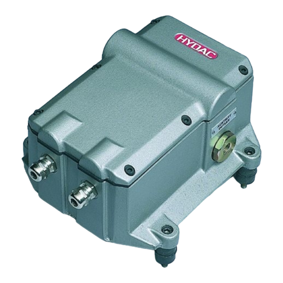
Hydac CS 2000 series Operating And Maintenance Manual (84 pages)
Contamination Sensor
Brand:
Hydac
| Category:
Accessories
| Size: 3 MB
Table of Contents
Table of Contents
3
1 General Safety Precautions
9
Obligations and Liability
9
Explanation of Symbols and Warnings, Etc
9
Basic Symbols
10
Proper/Designated Use
10
Improper Use
10
Informal Safety Precautions
11
Training and Instruction of Personnel
12
Safety Measures to be Followed in Normal Operation
12
Electrical Hazards
12
Maintenance, Servicing and Troubleshooting
13
Modifications to the CS
13
Cleaning the CS and Disposal of the Media and Agents Used
13
2 Packing, Transportation, Storage and Disposal
14
Transportation Packing
14
Storage
14
Storage Conditions
14
Disposal / Recycling and Decommissioning
14
3 Scope of Delivery
15
4 Technical Description of the CS
16
General Data
16
CS Design
17
Restrictions Pertaining to Use
17
Hydraulic Schematic
17
Hydraulic Schematic for Pressure/Viscosity Ranges 1 and 2
18
Hydraulic Schematic for Pressure/Viscosity Ranges 3 and 4
18
Hydraulic Schematic for CS 2Xxx0
18
5 Installation and Operation
19
Electrical Installation
19
Terminal Assignment
19
Electrical Connection of the CS
22
Selecting a Measurement Point
22
Hydraulic Connection of the CS
23
Removing the CS from the Hydraulic System
24
6 Description of the Measuring Modes
25
Mode M1: Measure
25
Mode M2: Measure and Switch
25
Mode M3: Filter until
25
Mode M4: Filter from until
25
Switching Behavior of the Relays
25
7 Analog Inputs
29
Connection Assignment as 1000 Series
29
Connection Assignment as 2000 Series
29
Hydaclab Wiring Diagrams
30
8 Serial RS232 Display and Parameter Setting Interface
31
Connecting the Serial RS232 Display Interface
31
Measured Value Output and Messages Via the RS 232 Display Interface
32
Parameter Setting Via the Serial RS232 Display Interface
32
Operating Mode
32
Parameter Mode
33
Measurement Interval
33
Measuring Mode
34
Settings for Measuring Mode M2
34
Settings for Measuring Mode M3
37
Settings for Measuring Mode M4
37
BUS Address and Measurement Point Name
38
IP-Address
39
Dry-Running Protection
40
PLC Interface
40
Display Interface
41
Adjusting Current Interface
42
Testing Current Interface
42
Flowcheck
42
Check Particle Sensor
43
Ma Inputs - Configure
43
Ma Inputs - Display Current Measured Values
44
Master Reset
45
9 PLC Interface Output Signals
46
10 DIN Measurement Bus Module (Option -2)
48
Interface
48
Bus Address
48
Settings of the Bus Address with DIP Switch
48
DIN Measurement Bus Commands
49
Commands
50
Command '8': Set Parameter
51
Command '9': Rear out Parameter
51
Command '11': Read Measured Particles (Differential) (Online)
51
Command '12': Read Measured Contamination Class Online)
53
Command '13': Stop Measurement
54
Command '14': Start Measurement
54
Command '17': Read out LED Current
54
Command '19': Set Parameter to Factory Settings
55
Command '109': Request Device Version
55
Parameter List / Parameter List
56
11 RS 232 Module (Option -0)
61
12 Ethernet Module (Option -5)
62
Setting the IP Address
62
Devices with an Ethernet Module Offer the Following 2 Applications
62
Transferring Commands Via the TCP/IP Protocol
62
CS 2000 as Webserver
63
Electrical Installation
64
13 Analog Module (Option -1)
65
14 Cleanliness Classes - Brief Overview
68
Cleanliness Class - ISO 4406:1999
68
ISO 4406 Table
68
Changes from ISO4406:1987 to ISO4406:1999
69
Cleanliness Class - SAE as 4059
70
SAE as 4059 Table
70
SAE Definition
71
Absolute Particle Count Larger than a Defined Particle Size
71
Specifying a Cleanliness Class for each Particle Size
71
Specifying the Highest Cleanliness Class Measured
71
Cleanliness Class - NAS 1638
72
15 Error Messages and Troubleshooting
73
16 Showing Display and Error Messages
74
17 Technical Data
75
18 Recalibration / Service
77
19 Customer Service
77
20 Differences between CS 203X / CS 213X / CS 223X
77
Display Output
77
PLC Interface
77
Limit Values for Relay Functions in Mode M2
77
Factory Default Settings
78
21 Model Code and Dimensions
79
Advertisement
Advertisement
Related Products
HYDAC CS 1000 Series
HYDAC CoCoS 1000
Hydac ContaminationSensor CS1220 VIMS
Hydac CSM 2000 series
Hydac CSI-B-1
Hydac CSI-C-11
Hydac CSI-Connect
Hydac CTM-EF-1230-Z-Z-Z
Hydac CTU12 Series
Hydac KINESYS HFI-MM C 7.5
Hydac Categories
Water Filtration Systems
Industrial Equipment
Accessories
Control Unit
Switch
More Hydac Manuals
Login
Sign In
OR
Sign in with Facebook
Sign in with Google
Upload manual
Upload from disk
Upload from URL