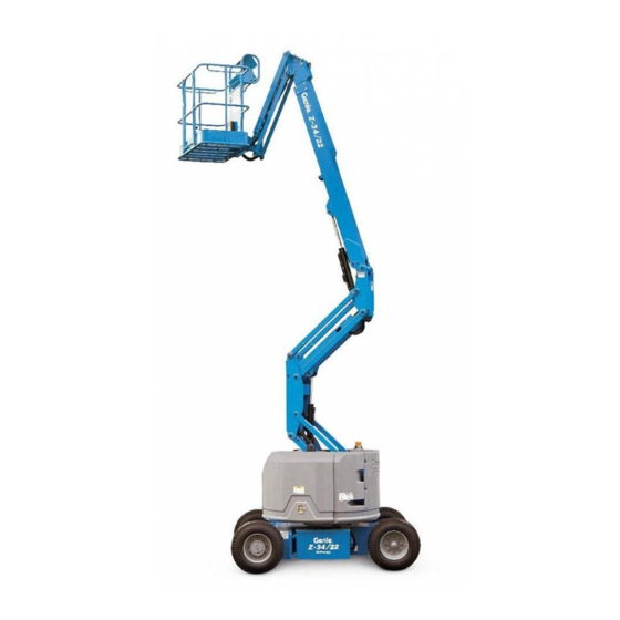
Sign In
Upload
Manuals
Brands
Genie Manuals
Boom Lifts
Z-30/20N
Genie Z-30/20N Manuals
Manuals and User Guides for Genie Z-30/20N. We have
6
Genie Z-30/20N manuals available for free PDF download: Service Manual, Maintenance Manual, Service And Repair Manual
Genie Z-30/20N Maintenance Manual (182 pages)
Brand:
Genie
| Category:
Boom Lifts
| Size: 8.52 MB
Table of Contents
Table of Contents
9
Models Included in this Manual
3
Introduction
3
Identifying the Correct Procedure for Your Model
4
Find Additional Manuals for Your Model
4
Revision History
5
Safety Rules
7
Table of Contents
9
Performance Specifications
15
Function Speeds - S-100, S-105 and S-100HD
15
Function Speeds - S-120, S-125 and S-120HD
16
Function Speeds - All Other Models
17
Maintenance Manual October 2018 Performance Specifications
18
Jib Boom down
19
Jib Boom Rotate
19
Jib Boom up
19
Primary Boom Extend
19
Primary Boom Retract
19
Secondary Boom down
19
Secondary Boom up
19
Turntable Rotate
20
Platform Level (10° Range of Motion)
21
Platform Rotate
21
Drive Speeds
23
Ansi/Csa
25
Tires and Wheels
26
Torque Specifications
26
Trax Torque Specifications
27
Engine Operator and Maintenance Manuals
28
Engine Specifications
28
Deutz Engine Models
29
Perkins Engine Models
30
Ford Engine Models
32
Kubota Engine Models
32
GM Engine Models
33
Continental Engine Models
34
Cummins Engine Models
34
Hydraulic Relief Valves
35
Hydraulic Specifications
35
Hydraulic and Drive Hub Fluid Capacities
38
Hydraulic Oil Specifications
40
Hydraulic Hose and Fitting Torque Specifications
43
Torque Procedure
44
Introduction
46
Maintenance Procedures
46
Maintenance Schedule
48
Pre-Delivery Preparation Report
49
Scheduled - Quarterly October 2018 Maintenance Inspection Report - Booms
50
Scheduled Maintenance Inspection Report - Quarterly or Frequent
50
Boom(S) and Platform
51
Drive Chassis
51
Scheduled Maintenance Inspection Report - Annual
51
Turntable Mechanicals and Hydraulics
51
Programmed Maintenance Inspection Report - Booms
52
Commissioning Procedures
53
Perform 50 Hour Service
53
Perform Engine Maintenance - 50 Hours
53
Perform 150 Hour Service
54
Check for Open Bulletins and Owner Registration
55
Quarterly Maintenance Procedures
55
Battery Inspection
56
Inspect the Electrical Wiring
58
Inspect the Electrical Contactor - DC / Bi-Energy Models
59
Check the Exhaust System
60
Inspect the Tires, Wheels and Lug Nut Torque
60
Check the Generator Belts and Pulleys, Bi-Energy Models
61
Check the Oscillate Directional Valve Linkage (if Equipped)
62
Visual Inspection of the Hydraulic Oil
63
Inspect the Hydraulic Filters
64
Check and Adjust the Engine RPM
65
Test the Ground Control Override
70
Test the Alarm Package (if Equipped
71
Test the Alarm Package (if Equipped)
71
Test the Emergency Power System
72
Test the Engine Idle Select - Engine Models
72
Test the Engine Idle Select Operation
72
Test the Fuel Select Operation - Gasoline/Lpg Models
74
Inspect the Calibration Decal - ALC1000 Models
75
Test the Recovery Mode System - ALC-1000 Models
76
Test the Recovery System - ALC-1000 Models
76
Test the Platform Self-Leveling
77
Confirm the Proper Brake Configuration
78
Test the Drive Brakes
78
Test the Drive Speed - Raised or Extended Position
79
Test the Drive Speed - Stowed Position
79
Test the Drive Speed - Raised and Extended Position
80
Test the Drive Speed - Raised and Extended, ALC1000 Models
80
Sx-105Xc, Sx-125Xc, Sx-135Xc
82
Test the Turntable Level Sensor
82
XC, SX-125 XC, SX-135 XC, SX-150 and SX-180
82
Test the Secondary Boom Angle Sensor
84
Test the Secondary Boom Angle Sensor - Z-135/70 and ZX-135/70
84
Test the Primary Boom Angle Sensor - Z-135/70 and
86
Test the Primary Boom Angle Sensor - Z-135/70 and ZX-135/70
86
Test the Primary Boom Angle Sensor
89
XC, SX-125 XC, SX-135 XC, SX-150 and SX-180
89
Test the Safety Envelope Limit Switches
94
Test the Safety Envelope Limit Switches - Z-135/70, ZX-135/70, SX-105
94
Test the Primary Boom Angle Sensor
98
Test the Primary Boom Angle Sensor - Z-80/60
98
Test the Safety Envelope and Circuits
99
Test the Safety Envelope and Circuits - Z-80/60
99
Check the Safety Envelope Limit Switches and Angle Sensor - S-60X, S-80X, and S-60XC to S60XC-45000
101
And S-125
103
Test the Safety Envelope and Circuits
103
Test the Aircraft Protection System (if Equipped)
109
Inspect the Boom Extend/Retract Cables - All Models
111
Test the Operator Protection Alarm (if Equipped
111
Test the Operator Protection Alarm (if Equipped)
111
Test the Recovery Mode System - ALC-600 Models
112
S60Xcm-101, S-65 XC, S-80 Hf, S-85 Hf, S-80 XC, S-85 XC
113
Test the Primary Boom Angle Sensor - S-60 XC from S60XCH-45001 and S60XCM-101, S-65 XC, S-80 HF, S-85 HF, S-80 XC, S-85 XC
115
Test the Primary Boom Angle Sensor - S-60XC from
115
Annual Maintenance Procedures
117
Grease the Turntable Rotation Bearing and Rotate Gear
117
Check the Turntable Rotation Bearing Bolts
118
Inspect for Turntable Bearing Wear
119
Check the Extendable Axle - S-100, S-105, S-120 and S-125
120
Perform Maintenance- Jib Rotate Bearing
121
Test the Bypass/Recovery Key Switch - ALC1000 Models
122
Grease the Platform Overload Mechanism (if Equipped)
124
S-80XC, S-85XC and Z-45XC Models)
125
Test the Platform Overload System - All Models
125
Test the Platform Overload System - ALC1000 Models
127
Test the Platform Load Sense System - S-60 HC
128
Inspect the Boom Extend/Retract Cables - S-60/65 and S-80/85 Models
129
Inspect the Boom Extend/Retract Cables
131
XC and SX-125 XC
131
Inspect the Boom Extend and Retract Cables - SX-135
133
Check the Drive Hub Oil Level and Fastener Torque
137
Test the Dual Capacity and Platform Overload System
139
XC, SX-125 XC and SX-135 XC
139
Test the Dual Capacity and Platform Overload System - S-60 XC from
141
Z-45 XC Models
141
XC, S-85 XC
142
And Z-62 Models
144
P0-1 Check the Track Tension and Fastener Torque, TRAX Models
144
Programmed Maintenance Procedures
144
P0-2 Check the Track Tension and Fastener Torque, TRAX Models
145
S-40 and S-45 Models
145
P0-3 Grease the Extendable Axles - S-100, S-105, S-120 and S-125
147
P0-4 Continental Engine Maintenance - under 1000 Hours
148
P0-5 Cummins Engine Maintenance - under 1000 Hours
149
P0-6 Deutz Engine Maintenance - under 1000 Hours
150
P0-7 Ford Engine Maintenance - under 1000 Hours
151
P0-8 Kubota Engine Maintenance - under 1000 Hours
152
P0-9 Perkins Engine Maintenance - under 1000 Hours
153
P0-10 GM .998L Engine Maintenance - under 1000 Hours
154
P0-11 GM 3.0L Engine Maintenance - under 1000 Hours
155
P1-1 Perform Engine Maintenance - 1000 Hours
156
P1-2 Replace the Drive Hub Oil
157
P2-1 Perform Engine Maintenance - 2000 Hours
160
P2-2 Test or Replace the Hydraulic Oil
162
P2-3 Replace the Hydraulic Filters
163
P2-4 Check the Free-Wheel Configuration
165
P2-5 Check the Boom Wear Pads
167
P2-6 Check the Extendable Axle Wear Pads - S-100, S-105, S-120, S-125, S-100HD and S-120HD
170
P2-7 Check the Turntable Rotation Gear Backlash
170
P2-8 Grease the Steer Axle Wheel Bearings, All 2WD Models, Except S-60, S-65, Z-60 DC/FE and Z-62
171
DC/FE and Z-62
173
P3-1 Perform Engine Maintenance - 3000 Hours
174
P4-1 Perform Engine Maintenance - 4000 Hours
175
P5-1 Perform Engine Maintenance - 5000 Hours
176
P6-1 Perform Engine Maintenance - 6000 Hours
176
P12-1 Perform Engine Maintenance - 12000 Hours
177
P12-2 Remove and Inspect the Boom Extend/Retract Cables
177
Cable Replacement Criteria
180
Advertisement
Genie Z-30/20N Service Manual (188 pages)
Brand:
Genie
| Category:
Boom Lifts
| Size: 10.95 MB
Table of Contents
April
2
Find a Manual for this Model
2
Serial Number Legend
5
Safety Rules
6
Table of Contents
8
Specifications
14
Machine Specifications
14
Machine Component Weights
15
Performance Specifications
16
Hydraulic Specification
17
Viscosity Index
17
Kinematic Viscosity
18
Fluid Properties
19
ISO Grade Viscosity Index
19
Cst @ 200°F / 100°C
19
Cst @ 104°F / 40°C
19
Hydraulic Component Specifications
20
Manifold Component Specifications
20
Machine Torque Specifications
21
Hydraulic Hose and Fitting Torque Specifications
22
Torque Procedure
23
SAE and Metric Fasteners Torque Charts
25
Scheduled Maintenance Procedures
26
Introduction
26
Pre-Delivery Preparation Report
29
Maintenance Inspection Report
31
Checklist a Procedures
32
Inspect the Manuals and Decals
32
Perform Pre-Operation Inspection
33
Perform Function Tests
33
Perform 30 Day Service
34
Grease the Turntable Rotation Bearing and Worm Drive Gear
34
Replace the Drive Hub Oil
35
Checklist B Procedures
36
Inspect the Battery
36
Inspect the Electrical Wiring
37
Inspect the Tires, Wheels and Lug Nut Torque
38
Confirm the Proper Brake Configuration
39
Check the Drive Hub Oil Level and Fastener Torque
39
Test the Ground Control Override
40
Test the Platform Self-Leveling
40
Test the Drive Brakes
41
Test the Drive Speed - Stowed Position
41
Test the Drive Speed - Raised or Extended Position
42
Test the Alarm Package (if Equipped)
43
Test the Turntable Rotation Stop
44
Check the Electrical Contactors
44
Perform Hydraulic Oil Analysis
45
Test the Emergency Power System
45
Checklist C Procedures
47
Grease the Platform Overload Mechanism (if Equipped)
47
Test the Platform Overload System (if Equipped)
47
Checklist D Procedures
49
Check the Boom Wear Pads
49
Check the Free-Wheel Configuration
50
Check the Turntable Rotation Bearing Bolts
51
Replace the Drive Hub Oil
52
Replace the Hydraulic Tank Return Filter Element
52
Inspect for Turntable Bearing Wear
53
Checklist E Procedures
54
Test or Replace the Hydraulic Oil
54
Grease the Steer Axle Wheel Bearings
56
April
57
Repair Procedures
58
Introduction
58
Platform Controls
60
Controllers
60
Platform Components
62
Platform Leveling Slave Cylinder
62
Platform Rotator
63
Platform Overload System
64
Jib Boom Components
67
Platform Overload System
67
Jib Boom Bell Crank (Models Without Rotating Jib Boom)
68
Jib Boom Bell Crank (Models with Rotating Jib Boom)
69
Jib Boom Lift Cylinder
71
Primary Boom Components
72
Cable Track
72
How to Repair the Primary Boom Cable Track
72
Primary Boom
73
How to Remove the Primary Boom
73
How to Disassemble the Primary Boom
75
Primary Boom Lift Cylinder
76
Primary Boom Extension Cylinder
78
Platform Leveling Master Cylinder
80
Secondary Boom Components
81
Secondary Boom
82
Secondary Boom Lift Cylinder
87
Hydraulic Pump
90
Auxiliary and Function Pump
90
Manifolds
91
7-1 Function Manifold Components
91
Valve Adjustments - Function Manifold
95
How to Adjust the System Relief Valve
95
How to Adjust the Primary Boom down Relief Valve
95
How to Adjust the Secondary Boom down Relief Valve
96
How to Adjust the Primary Boom Extend Relief Valve
96
How to Adjust the Turntable Rotate Relief Valve
97
Jib Boom and Platform / Jib Boom Rotate Manifold Components
98
Valve Coils
100
How to Test a Coil Diode
101
Turntable Rotation Components
103
Turntable Rotation Hydraulic Motor
103
Steer Axle Components
104
Hub and Bearings
104
How to Remove the Hub and Bearings
104
How to Install the Hub and Bearings
104
Non-Steer Axle Components
106
Motor Controller
106
Fault Codes
107
Introduction
107
Fault Code Charts
109
Schematics
112
Introduction
112
Section 6 Schematics
112
Electrical Symbol Legend
113
Hydraulic Symbols Legend
114
Limit Switch Location Legend
115
Electrical Schematics - Options
116
April
116
Power Cable Wiring Diagram
117
Drive Contactor Panel Wiring Diagram
118
Manifold and Limit Switch Wiring Diagram
121
LVI/BCI Option Wiring Diagram
122
Work and Drive Lights Option
125
CTE Option, (CE Models)
126
Charger Interlock Option
129
Hydraulic Schematics
130
Hydraulic Schematic
131
Electrical Schematics - ANSI / CSA / as Models
132
Electrical Schematic, (ANSI / CSA / AS) (before Serial Numbers Z30N10-12119, Z34N10-8857 and Z3410-7774)
133
Ground Control Box Terminal Strip Wiring Diagram, (ANSI / CSA / AS) (before Serial Numbers Z3010-12119, Z34N10-8857 and Z3410-7774)
136
Ground Control Box Terminal Strip Wiring Diagram, (ANSI / CSA / AS) (before Serial Numbers Z3010-12119, Z34N10-8857 and Z3410-7774)
137
Ground Control Box Switch Panel Wiring Diagram, (ANSI / CSA / AS), (before Serial Numbers Z30N10-12119, Z34N10-8857 and Z3410-7774)
138
Platform Control Box Wiring Diagram, (ANSI / CSA / AS) (before Serial Numbers Z30N10-12119, Z34N10-8857 and Z3410-7774)
141
Electrical Schematics - CE Models
142
Electrical Schematic, (CE), (before Serial Numbers Z30N10-12119, Z34N10-8857 and Z3410-7774)
143
Ground Control Box Terminal Strip Wiring Diagram, (CE) (before Serial Numbers Z30N10-12119, Z34N10-8857 and Z3410-7774)
147
Ground Control Box Switch Panel Wiring Diagram, (CE) (before Serial Numbers Z30N10-12119, Z34N10-8857 and Z3410-7774)
148
Platform Control Box Wiring Diagram, (CE) (before Serial Numbers Z30N10-12119, Z34N10-8857 and Z3410-7774)
151
Electrical Schematics - ANSI and CSA Models
152
Electrical Schematic, (ANSI / CSA), (from Serial Numbers Z30N10-12119, Z34N10-8857 and Z3410-7774 to Z30N13-14695, Z34N13-10622 and Z3413-9441 )
153
Electrical Schematic, (ANSI / CSA)
157
Z3413-9442 to Z30N14-15221, Z34N14-10983 and Z3414-9685)
157
Ground Control Box Terminal Strip Wiring Diagram, (ANSI / CSA) (from Serial Numbers Z30N10-12119, Z34N10-8857 and Z3410-7774 to Z30N13-14695, Z34N13-10622 and Z3413-9441)
161
Ground Control Box Switch Panel Wiring Diagram, (ANSI / CSA), (from Serial Numbers Z30N10-12119, Z34N10-8857 and Z3410-7774)
162
Platform Control Box Wiring Diagram, (ANSI / CSA), (from Serial Numbers Z30N10-12119, Z34N10-8857 and Z3410-7774)
167
Z3413-9442 to Z30N14-15221, Z34N14-10983 and Z3414-9685)
168
Electrical Schematics - as / CE Models
170
Electrical Schematic, (as / CE), (from Serial Numbers Z30N10-12119, Z34N10-8857 and Z3410-7774 to Z30N13-14695, Z34N13-10622 and Z3413-9441)
171
Electrical Schematic, (as / CE)
175
Z3413-9442 to Z30N14-15221, Z34N14-10983 and Z3414-9685)
175
Ground Control Box Terminal Strip Wiring Diagram, (as / CE) (from Serial Numbers Z30N10-12119, Z34N10-8857 and Z3410-7774 to Z30N13-14695, Z34N13-10622 and Z3413-9441)
179
Ground Control Box Switch Panel Wiring Diagram, (as / CE) (from Serial Numbers Z30N10-12119, Z34N10-8857 and Z3410-7774 to Z30N13-14695, Z34N13-10622 and Z3413-9441)
181
Ground Control Box Terminal Strip Wiring Diagram, (as / CE) (from Serial Numbers Z30N13-14696, Z34N13-10623 and Z3413-9442 to Z30N14-15221, Z34N14-10983 and Z3414-9685)
183
Platform Control Box Wiring Diagram, (as / CE) (from Serial Numbers Z30N10-12119, Z34N10-8857 and Z3410-7774 to Z30N13-14695, Z34N13-10622 and Z3413-9441)
185
Platform Control Box Wiring Diagram, (as / CE)
186
Z34N14-10983 and Z3414-9685
186
Genie Z-30/20N Maintenance Manual (178 pages)
Brand:
Genie
| Category:
Boom Lifts
| Size: 8.21 MB
Table of Contents
Table of Contents
9
Maintenance Procedures
42
Introduction
42
Maintenance Schedule
44
Pre-Delivery Preparation Report
45
Scheduled - Quarterly April 2018 Maintenance Inspection Report - Booms
46
Scheduled Maintenance Inspection Report - Quarterly or Frequent
46
Scheduled Maintenance Inspection Report - Annual
47
Programmed Maintenance Inspection Report - Booms
48
Commissioning Procedures
49
Perform 50 Hour Service
49
Perform Engine Maintenance - 50 Hours
49
Perform 150 Hour Service
50
Check for Open Bulletins and Owner Registration
51
Quarterly Maintenance Procedures
51
Battery Inspection
52
Inspect the Electrical Wiring
54
Inspect the Electrical Contactor - DC / Bi-Energy Models
55
Check the Exhaust System
56
Inspect the Tires, Wheels and Lug Nut Torque
56
Check the Generator Belts and Pulleys, Bi-Energy Models
57
Check the Oscillate Directional Valve Linkage (if Equipped)
58
Visual Inspection of the Hydraulic Oil
59
Inspect the Hydraulic Filters
60
Check and Adjust the Engine RPM
61
Test the Ground Control Override
66
Test the Alarm Package (if Equipped
67
Test the Alarm Package (if Equipped)
67
Test the Emergency Power System
68
Test the Engine Idle Select - Engine Models
68
Test the Engine Idle Select Operation
68
Test the Fuel Select Operation - Gasoline/Lpg Models
70
Inspect the Calibration Decal - ALC1000 Models
71
Test the Recovery Mode System - ALC-1000 Models
72
Test the Recovery System - ALC-1000 Models
72
Test the Platform Self-Leveling
73
Confirm the Proper Brake Configuration
74
Test the Drive Brakes
74
Test the Drive Speed - Raised or Extended Position
75
Test the Drive Speed - Stowed Position
75
Test the Drive Speed - Raised and Extended Position
76
Test the Drive Speed - Raised and Extended, ALC1000 Models
76
Test the Turntable Level Sensor
78
XC, SX-125 XC, SX-135 XC, SX-150 and SX-180
78
Test the Secondary Boom Angle Sensor - Z-135/70 and ZX-135/70
80
Test the Turntable Level Sensor
81
Test the Primary Boom Angle Sensor - Z-135/70 and ZX-135/70
82
Test the Secondary Boom Angle Sensor
82
Test the Primary Boom Angle Sensor
85
XC, SX-125 XC, SX-135 XC, SX-150 and SX-180
85
Test the Safety Envelope Limit Switches
90
XC, SX-125 XC, SX-135 XC, SX-150 and SX-180
90
Test the Primary Boom Angle Sensor
94
Test the Primary Boom Angle Sensor - Z-80/60
94
Test the Safety Envelope and Circuits
95
Test the Safety Envelope and Circuits - Z-80/60
95
Check the Safety Envelope Limit Switches and Angle
97
Check the Safety Envelope Limit Switches and Angle Sensor - S-60X, S-60XC and S-80X
97
And S-125
99
Test the Safety Envelope and Circuits
99
Test the Aircraft Protection System (if Equipped
105
Test the Aircraft Protection System (if Equipped)
105
Inspect the Boom Extend/Retract Cables - All Models
107
Test the Operator Protection Alarm (if Equipped)
107
Test the Recovery Mode System - ALC-600 Models
108
Test the Turntable Level Sensor - S-80 XC and S-85 XC
109
Test the Primary Boom Angle Sensor - S-80 XC, S-85 XC
111
Annual Maintenance Procedures
113
Grease the Turntable Rotation Bearing and Rotate Gear
113
Check the Turntable Rotation Bearing Bolts
114
Inspect for Turntable Bearing Wear
115
Check the Extendable Axle - S-100, S-105, S-120 and S-125
116
Perform Maintenance- Jib Rotate Bearing
117
Test the Bypass/Recovery Key Switch - ALC1000 Models
118
Grease the Platform Overload Mechanism (if Equipped)
120
All Models, Except ALC1000 and S-60HC Models
121
Test the Platform Overload System
121
Test the Platform Overload System - ALC1000 Models
123
Test the Platform Load Sense System - S-60 HC
124
Inspect the Boom Extend/Retract Cables - S-60 and S-80 Models
125
Inspect the Boom Extend/Retract Cables - S-100, S-105, S-120, S-125, SX-105 XC and SX-125 XC
127
Inspect the Boom Extend and Retract Cables
129
XC, SX-150 and SX-180
129
Check the Drive Hub Oil Level and Fastener Torque
133
Test the Dual Capacity and Platform Overload System
135
Test the Dual Capacity and Platform Overload System - S-80 XC and SX-85 XC
135
XC, SX-125 XC and SX-135 XC
135
Z-45 XC Models
137
P0-1 Check the Track Tension and Fastener Torque, TRAX Models
140
Programmed Maintenance Procedures
140
S-60, S-65 and Z-62 Models
140
P0-2 Check the Track Tension and Fastener Torque, TRAX Models
141
S-40 and S-45 Models
141
P0-3 Grease the Extendable Axles - S-100, S-105, S-120 and S-125
143
P0-4 Continental Engine Maintenance - under 1000 Hours
144
P0-5 Cummins Engine Maintenance - under 1000 Hours
145
P0-6 Deutz Engine Maintenance - under 1000 Hours
146
P0-7 Ford Engine Maintenance - under 1000 Hours
147
P0-8 Kubota Engine Maintenance - under 1000 Hours
148
P0-9 Perkins Engine Maintenance - under 1000 Hours
149
P0-10 GM .998L Engine Maintenance - under 1000 Hours
150
P0-11 GM 3.0L Engine Maintenance - under 1000 Hours
151
P1-1 Perform Engine Maintenance - 1000 Hours
152
P1-2 Replace the Drive Hub Oil
153
P2-1 Perform Engine Maintenance - 2000 Hours
156
P2-2 Test or Replace the Hydraulic Oil
158
P2-3 Replace the Hydraulic Filters
159
P2-4 Check the Free-Wheel Configuration
161
P2-5 Check the Boom Wear Pads
163
P2-6 Check the Extendable Axle Wear Pads - S-100, S-105, S-120, S-125, S-100HD and S-120HD
166
P2-7 Check the Turntable Rotation Gear Backlash
166
P2-8 Grease the Steer Axle Wheel Bearings, All 2WD Models, Except S-60, S-65, Z-60 DC/FE and Z-62
167
P2-9 Grease the Steer Axle Wheel Bearings, 2WD Models - S-60, S-65, Z-60 DC/FE and Z-62
169
P3-1 Perform Engine Maintenance - 3000 Hours
170
P4-1 Perform Engine Maintenance - 4000 Hours
171
P5-1 Perform Engine Maintenance - 5000 Hours
172
P6-1 Perform Engine Maintenance - 6000 Hours
172
P12-1 Perform Engine Maintenance - 12000 Hours
173
P12-2 Remove and Inspect the Boom Extend/Retract Cables
173
Cable Replacement Criteria
176
Advertisement
Genie Z-30/20N Service Manual (161 pages)
Brand:
Genie
| Category:
Lifting Systems
| Size: 2.03 MB
Table of Contents
Introduction
2
Serial Number Information
2
Serial Number Legend
3
Z-30/20N • Z-30/20N RJ • Z-34/22 • Z-34/22N Part
4
Safety Rules
5
Table of Contents
7
C Machine Specifications
13
Performance Specifications
14
Hydraulic Oil Specifications
15
Hydraulic Component Specifications
15
Manifold Component Specifications
16
Machine Torque Specifications
16
Hydraulic Hose and Fitting Torque Specifications
17
Pre-Delivery Preparation
21
Maintenance Inspection Report
23
Checklist a Procedures
24
Inspect the Manuals and Decals
24
Perform Pre-Operation Inspection
25
Perform Function Tests
25
Perform 30 Day Service
26
Grease the Turntable Rotation Bearing and Worm Drive Gear
26
Replace the Drive Hub Oil
27
Checklist B Procedures
28
Inspect the Electrical Wiring
29
Test the Key Switch
30
Confirm the Proper Brake Configuration
31
Check the Oil Level in the Drive Hubs and Mounting Bolt Torque
32
Test the Ground Control Override
32
Test the Platform Self-Leveling
33
Test the Drive Brakes
33
Test the Drive Speed - Stowed Position
34
Test the Drive Speed - Raised or Extended Position
34
Test the Alarm Package (if Equipped)
35
Test the Turntable Rotation Stop
36
Check the Electrical Contactors
36
Perform Hydraulic Oil Analysis
37
Checklist C Procedures
38
Grease the Platform Overload Mechanism (if Equipped)
38
Test the Platform Overload System (if Equipped)
38
Checklist D Procedures
41
Check the Primary Boom Wear Pads
41
Check the Free-Wheel Configuration
42
Check the Turntable Rotation Bearing Bolts
43
Replace the Drive Hub Oil
44
Replace the Hydraulic Tank Return Filter Element
44
Inspect for Turntable Bearing Wear
45
Checklist E Procedures
47
Test or Replace the Hydraulic Oil
47
Grease the Steer Axle Wheel Bearings
49
Platform Controls
52
Controllers
52
Platform Components
54
Platform Leveling Slave Cylinder
54
Platform Rotator
55
Platform Overload System (if Equipped)
57
Jib Boom Components
59
Jib Boom
59
Jib Boom Bell Crank (Models Without Rotating Jib Boom)
60
Jib Boom Rotator (Models with Rotating Jib Boom)
61
Jib Boom Lift Cylinder
63
Primary Boom Components
64
Cable Track
64
Primary Boom
64
Primary Boom Lift Cylinder
68
Extension Cylinder
69
Platform Leveling Master Cylinder
70
Secondary Boom Components
72
Secondary Boom
73
Secondary Boom Lift Cylinder
78
A Hydraulic Pump
80
Auxiliary and Function Pump
80
Function Manifold Components
82
Valve Adjustments - Function Manifold
86
Jib Boom and Platform / Jib Boom Rotate Manifold Components
89
Valve Coils
91
Turntable Rotation Components
93
Turntable Rotation Hydraulic Motor
93
Steer Axle Components
94
Hub and Bearings
94
A Motor Controller
95
Fault Code Chart
99
Electrical Symbols Legend
104
Hydraulic Symbols Legend
105
Limit Switch Location Legend
106
Electrical Schematic, (ANSI / CSA / AS)
107
(Before Serial Numbers Z30N10-12119, Z34N10-8857 and Z3410-7774)
108
Ground Control Box Terminal Strip Wiring Diagram, (ANSI / CSA / AS)
111
(Before Serial Numbers Z30N10-12119, Z34N10-8857 and Z3410-7774)
112
Ground Control Box Switch Panel Wiring Diagram, (ANSI / CSA / AS)
113
(Before Serial Numbers Z30N10-12119, Z34N10-8857 and Z3410-7774)
113
Platform Control Box Wiring Diagram, (ANSI / CSA / AS)
115
(Before Serial Numbers Z30N10-12119, Z34N10-8857 and Z3410-7774)
115
Electrical Schematic (CE)
117
(Before Serial Numbers Z30N10-12119, Z34N10-8857 and Z3410-7774)
117
Ground Control Box Terminal Strip Wiring Diagram, (CE)
121
(Before Serial Numbers Z30N10-12119, Z34N10-8857 and Z3410-7774)
121
Ground Control Box Switch Panel Wiring Diagram, (CE)
123
Before Serial Numbers Z30N10-12119, Z34N10-8857 and Z3410-7774)
125
Platform Control Box Wiring Diagram, (CE)
125
(Before Serial Numbers Z30N10-12119, Z34N10-8857 and Z3410-7774)
126
Electrical Schematic, (ANSI / CSA)
127
(From Serial Numbers Z30N10-12119, Z34N10-8857 and Z3410-7774)
127
Ground Control Box Terminal Strip Wiring Diagram, (ANSI / CSA)
131
(From Serial Numbers Z30N10-12119, Z34N10-8857 and Z3410-7774)
132
Ground Control Box Switch Panel Wiring Diagram, (ANSI / CSA)
133
From Serial Numbers Z30N10-12119, Z34N10-8857 and Z3410-7774)
135
Platform Control Box Wiring Diagram, (ANSI / CSA)
135
(From Serial Numbers Z30N10-12119, Z34N10-8857 and Z3410-7774)
136
Ground Control Box Terminal Strip Wiring Diagram, (as / CE)
141
(From Serial Numbers Z30N10-12119, Z34N10-8857 and Z3410-7774)
146
Platform Control Box Wiring Diagram, (as / CE)
146
Power Cable Wiring Diagram
147
Drive Contactor Panel Wiring Diagram
149
Manifold and Limit Switch Wiring Diagram
151
LVI/BCI Option Wiring Diagram
153
Charger Interlock Option
155
CTE Option, (CE Models)
157
Hydraulic Schematic
159
Genie Z-30/20N Service And Repair Manual (131 pages)
Lift Capacity 500 lbs
Brand:
Genie
| Category:
Lifting Systems
| Size: 7.46 MB
Table of Contents
Introduction
2
Find a Manual for this Model
2
September
2
Revision History
3
Serial Number Legend
4
Safety Rules
5
Table of Contents
7
Specifications
11
Machine Specifications
11
Performance Specifications
12
Hydraulic Specification
13
Hydraulic Component Specifications
15
Manifold Component Specifications
15
Machine Torque Specifications
16
Hydraulic Hose and Fitting Torque Specifications
17
Torque Procedure
18
SAE and Metric Fasteners Torque Charts
20
Repair Procedures
21
Platform Controls
23
Controllers
23
Platform Components
25
Platform Leveling Slave Cylinder
25
Platform Rotator
26
Platform Overload System
27
Jib Boom Components
30
Jib Boom Bell Crank (Models Without Rotating Jib Boom)
31
Jib Boom Bell Crank (Models with Rotating Jib Boom)
31
Jib Boom Bell Crank (Models with Rotating Jib Boom)
32
Jib Boom Lift Cylinder
34
Primary Boom Components
35
Cable Track
35
How to Repair the Primary Boom Cable Track
35
Primary Boom
35
September
35
How to Remove the Primary Boom
36
How to Disassemble the Primary Boom
38
Primary Boom Lift Cylinder
39
Primary Boom Extension Cylinder
41
Platform Leveling Master Cylinder
43
Secondary Boom Components
44
Secondary Boom
45
Secondary Boom Lift Cylinders
50
Hydraulic Pump
53
Auxiliary and Function Pump
53
Manifolds
54
7-1 Function Manifold Components
54
Valve Adjustments - Function Manifold
58
How to Adjust the System Relief Valve
58
How to Adjust the Primary Boom down Relief Valve
58
How to Adjust the Secondary Boom down Relief Valve
59
How to Adjust the Primary Boom Extend Relief Valve
59
How to Adjust the Turntable Rotate Relief Valve
60
Jib Boom and Platform / Jib Boom Rotate Manifold Components
61
Valve Coils
63
How to Test a Coil Diode
64
Turntable Rotation Components
65
Turntable Rotation Hydraulic Motor
65
Steer Axle Components
66
Hub and Bearings
66
How to Remove the Hub and Bearings
66
How to Install the Hub and Bearings
66
Non-Steer Axle Components
67
Motor Controller
67
Fault Codes
68
September
68
Fault Code Charts
70
Schematics
73
Section 5 Schematics
73
Electrical Symbol Legend
74
Hydraulic Symbols Legend
75
Limit Switch Location Legend
76
Electrical Schematics - Options
77
Power Cable Wiring Diagram
77
Electrical Schematics – Options
77
Drive Contactor Panel Wiring Diagram
79
Manifold and Limit Switch Wiring Diagram
81
LVI/BCI Option Wiring Diagram
83
Charger Interlock Option
85
CTE Option, (CE Models)
87
Hydraulic Schematics
89
Hydraulic Schematic
89
Electrical Schematics - ANSI / CSA / as Models
91
Electrical Schematic, (ANSI / CSA / AS) (before Serial Numbers Z30N10-12119, Z34N10-8857 and Z3410-7774)
91
Electrical Schematics – ANSI / CSA / as Models
91
Ground Control Box Terminal Strip Wiring Diagram, (ANSI / CSA / as before Serial Numbers Z3010-12119, Z34N10-8857 and Z3410-7774)
93
Ground Control Box Terminal Strip Wiring Diagram, (ANSI / CSA / AS) (before Serial Numbers Z3010-12119, Z34N10-8857 and Z3410-7774)
95
Ground Control Box Terminal Strip Wiring Diagram, (ANSI / CSA / AS) (before Serial Numbers Z3010-12119, Z34N10-8857 and Z3410-7774)
96
Ground Control Box Switch Panel Wiring Diagram, (ANSI / CSA / as before Serial Numbers Z30N10-12119, Z34N10-8857 and Z3410-7774)
97
Ground Control Box Switch Panel Wiring Diagram, (ANSI / CSA / AS) (before Serial Numbers Z30N10-12119, Z34N10-8857 and Z3410-7774)
98
Platform Control Box Wiring Diagram, (ANSI / CSA / AS) (before Serial Numbers Z30N10-12119, Z34N10-8857 and Z3410-7774)
99
Platform Control Box Wiring Diagram, (ANSI / CSA / as before Serial Numbers Z30N10-12119, Z34N10-8857 and Z3410-7774)
100
Electrical Schematics - CE Models
101
Electrical Schematic, (CE), (before Serial Numbers Z30N10-12119, Z34N10-8857 and Z3410-7774)
101
September
101
Ground Control Box Terminal Strip Wiring Diagram, (CE), (before Serial Numbers Z30N10-12119, Z34N10-8857 and Z3410-7774)
105
Ground Control Box Switch Panel Wiring Diagram, (CE) (before Serial Numbers Z30N10-12119, Z34N10-8857 and Z3410-7774)
107
Platform Control Box Wiring Diagram, (CE) (before Serial Numbers Z30N10-12119, Z34N10-8857 and Z3410-7774)
109
Electrical Schematics - ANSI and CSA Models
111
Electrical Schematic, (ANSI / CSA), (from Serial Numbers Z30N10-12119, Z34N10-8857 and Z3410-7774)
111
Electrical Schematics – ANSI and CSA Models
111
Ground Control Box Terminal Strip Wiring Diagram, (ANSI / CSA), (from Serial Numbers Z30N10-12119, Z34N10-8857 and Z3410-7774)
115
Ground Control Box Switch Panel Wiring Diagram, (ANSI / CSA from Serial Numbers Z30N10-12119, Z34N10-8857 and Z3410-7774)
117
Ground Control Box Switch Panel Wiring Diagram, (ANSI / CSA), (from Serial Numbers Z30N10-12119, Z34N10-8857 and Z3410-7774)
118
Platform Control Box Wiring Diagram, (ANSI / CSA), (from Serial Numbers Z30N10-12119, Z34N10-8857 and Z3410-7774)
119
Electrical Schematics - as / CE Models
121
Electrical Schematic, (as / CE), (from Serial Numbers Z30N10-12119, Z34N10-8857 and Z3410-7774)
121
Electrical Schematics – as / CE Models
121
Ground Control Box Terminal Strip Wiring Diagram, (as / CE), (from Serial Numbers Z30N10-12119, Z34N10-8857 and Z3410-7774)
125
Ground Control Box Switch Panel Wiring Diagram, (as / CE) (from Serial Numbers Z30N10-12119, Z34N10-8857 and Z3410-7774)
127
Platform Control Box Wiring Diagram, (as / CE), (from Serial Numbers Z30N10-12119, Z34N10-8857 and Z3410-7774)
129
Genie Z-30/20N Service Manual (121 pages)
Brand:
Genie
| Category:
Lifting Systems
| Size: 5.8 MB
Table of Contents
Table of Contents
5
Introduction
2
Table of Contents
5
Machine Specifications
11
Performance Specifications
11
Hydraulic Specifications
12
Manifold Component Specifications
13
Machine Torque Specifications
13
Hydraulic Hose and Fitting Torque Specifications
14
Observe and Obey
15
About this Section
15
Pre-Delivery Preparation
17
Maintenance Inspection Report
19
Checklist a Procedures
20
Perform Pre-Operation Inspection
20
Perform Function Tests
20
Perform 30 Day Service
21
Grease the Turntable Rotation Bearing and Worm Drive Gear
21
Checklist B Procedures
22
Check the Batteries
22
Inspect the Electrical Wiring
23
Test the Key Switch
24
Check the Lug Nut Torque (Including the Tires and Wheels)
24
Confirm the Proper Brake Configuration
25
Check the Oil Level in the Drive Hubs
25
Test the Ground Control Override
26
Test the Platform Self-Leveling
26
Test the Drive Brakes
27
Test the Drive Speed - Stowed Position
27
Test the Drive Speed - Raised or Extended Position
28
Test the Alarm Package (if Equipped)
28
Test the Turntable Rotation Stop
29
Check the Electrical Contactors
30
Perform Hydraulic Oil Analysis
30
Checklist C Procedures
31
Grease the Platform Overload Mechanism (if Equipped)
31
Test the Platform Overload System (if Equipped)
31
Checklist D Procedures
34
Check the Primary Boom Wear Pads
34
Check the Free-Wheel Configuration
35
Check the Turntable Rotation Bearing Bolts
36
Replace the Drive Hub Oil
37
Replace the Hydraulic Tank Return Filter Element
37
Calibrate the Platform Overload System (if Equipped)
38
B Checklist E Procedures
38
Test or Replace the Hydraulic Oil
40
Gradually. Do Not Allow Oil to Squirt
41
Grease the Steer Axle Wheel Bearings
42
Platform Controls
46
Controllers
46
Electrocution Hazard. Contact with Electrically Charged Circuits Could Result in Death or Serious Injury
46
Platform Components
48
Platform Leveling Slave Cylinder
48
Platform Rotator
49
Jib Boom Components
51
Jib Boom
51
Jib Boom Bell Crank (Models Without Rotating Jib Boom)
52
Jib Boom Rotator (Models with Rotating Jib Boom)
53
Jib Boom Lift Cylinder
55
Primary Boom Components
56
Cable Track
56
Primary Boom
56
Primary Boom Lift Cylinder
60
Extension Cylinder
61
Platform Leveling Master Cylinder
62
Secondary Boom Components
64
Secondary Boom
65
Secondary Boom Lift Cylinder
70
Hydraulic Pumps
72
Auxiliary and Function Pump
72
Manifolds
74
Function Manifold Components
74
Valve Adjustments - Function Manifold
78
Jib Boom and Platform / Jib Boom Rotate Manifold Components
81
Valve Coils
82
Turntable Rotate Components
84
Turntable Rotation Hydraulic Motor
84
Or Spray
84
Steer Axle Components
85
Hub and Bearings
85
Motor Controller
86
Remove All Rings, Watches and Other Jewelry
86
Troubleshooting and Repair Procedures Shall be Completed by a Person Trained and Qualified on the Repair of this Machine
87
Immediately Tag and Remove from Service a Damaged or Malfunctioning Machine
87
Repair any Machine Damage or Malfunction before Operating the Machine
87
Before Troubleshooting
87
Read, Understand and Obey the Safety Rules and Operating Instructions Printed in the Genie Z-30/20N Operator's Manual on Your Machine
87
Be Sure that All Necessary Tools and Test Equipment Are Available and Ready for Use
87
Bodily Injury Hazard. Spraying
87
Hydraulic Oil Can Penetrate and Burn Skin. Loosen Hydraulic
87
Connections very Slowly to Allow
87
The Oil Pressure to Dissipate
87
Fault Code Chart
89
Schematics
93
Load Sensor Option Diagram (before Serial Number 6290)
94
Section 6 • Schematics
94
Electrical Symbols Legend
95
Hydraulic Symbols Legend
96
Power Cable Diagram (before Serial Number 6290)
97
Power Cable Diagram (after Serial Number 6289)
99
Electrical Schematic (before Serial Number 6290)
102
Electrical Schematic (after Serial Number 6289)
106
Ground Control Panel Wiring Diagram (before Serial Number 6290)
109
Ground Control Panel Wiring Diagram (after Serial Number 6289)
111
Platform Control Box Wiring Diagram (before Serial Number 6290)
113
Platform Control Box Wiring Diagram (after Serial Number 6289)
115
April 2004
115
Power Panel Wiring Diagram
117
Hydraulic Schematic
119
Advertisement
Related Products
Genie Z-30
Genie Z-30HD
Genie Z-30N
Genie Z-30/20N RJ' Z-34/22N
Genie Z-30/20
Genie Z-30/20HD
Genie Z-34/22
Genie Z-34/22N
Genie Z-34 Bi-Energy
Genie Z-33/18
Genie Categories
Garage Door Opener
Lifting Systems
Boom Lifts
Security Camera
Digital Camera
More Genie Manuals
Login
Sign In
OR
Sign in with Facebook
Sign in with Google
Upload manual
Upload from disk
Upload from URL