Sign In
Upload
Manuals
Brands
Fujitsu Manuals
Printer
FI-590PRF Operators
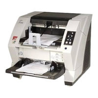
Fujitsu FI-590PRF Operators Imprinter Manuals
Manuals and User Guides for Fujitsu FI-590PRF Operators Imprinter. We have
3
Fujitsu FI-590PRF Operators Imprinter manuals available for free PDF download: Maintenance Manual, Operator's Manual
Fujitsu FI-590PRF Operators Maintenance Manual (327 pages)
Brand:
Fujitsu
| Category:
Scanner
| Size: 20 MB
Table of Contents
General Note
3
Table of Contents
5
Chapter 1 Overview
11
Scanner Overview
11
Features
11
Scanner Specification
12
Environmental Specification
14
Outer Dimensions
15
Installation Space Requirements
15
Appearance
16
Operator Panel
18
Document Specification
19
Document Size
19
Document Quality
20
Maximum Document Loading Capacity
21
Paper Weight
21
Hole-Punching Prohibited Areas
22
Multi Feed Detection Conditions
23
Background Color Areas
24
Job Separation Sheet
25
Scanning Mixed Documents
26
Condition for De-Skew and Automatic Document Size Detection (Automatic Cropping)
27
Chapter 2 Installation
28
Unpacking the Scanner
28
Installing the Scanner
29
For Safety Installation
29
Installation
29
Installing the Scanner Application
31
Chapter 3 Operation and Daily Maintenance
32
Basic Operation
32
Power ON/OFF
32
Opening or Closing the Hopper
33
Opening and Closing ADF
35
Opening and Closing Top Cover
36
Setting the Hopper Height
37
Loading Documents on the Hopper
38
Setting up the Stacker
41
Using the Document Smoother
44
Adjusting the Paper Thickness
45
Scanning Documents
47
Starting Scanning with Button
47
Feeding Documents Manually
48
Continuous Feed
50
How to Use the Scanner Driver
52
Before Using Scan/Send to Button
53
Resuming from Power Saving Mode
54
Scanning Documents with Different Widths
55
Cleaning
57
Cleaning Area and Cleaning Frequency
57
Cleaning the Pad
58
Cleaning the Rollers (with the Cleaning Sheet)
59
Cleaning the Rollers (with a Lint-Free Cloth)
61
Cleaning the Transport Path and the Sensors
64
Cleaning the Feed Rollers and Pinch Rollers
66
Replacing Consumables
67
Consumables and Replacement Cycle
67
How to Check and Reset the Consumables Counter
68
Replacing the Pad
71
Rev DATE
71
Maintenance Manual P1Pa03450-B00X/6
71
Replacing the Pick Roller
72
Replacing the Separator Rollers
73
Replacing the Brake Roller
75
Scanner Settings
77
Software Operation Panel
77
Opening the Software Operation Panel
77
Settings
78
Periodical Replacement Parts
80
Chapter 4 Scanner Operation Description
81
ADF Unit
81
Reading Station
87
Controller
88
Cable Connection Diagram
90
Diagram of Power Supply System
93
Chapter 5 Troubleshooting
95
Function Number Display Sequence at Power-On
95
Temporary Errors and Alarms
96
Temporary Errors
96
Alarms
96
Detail Code
96
Troubleshooting
97
How to Troubleshoot
98
Scanner Does Not Turn on (no Display on the Operator Panel)
98
Power Button on Operator Panel Does Not Function. Only the Main Power Switch at Rear of the Scanner Turns ON/OFF the Scanner
98
Scanning Does Not Start
98
Scanned Image Is Distorted
99
Resolution or Gradation on Scanned Image Is Unsatisfactory
99
Too Much Jitter on Scanned Image
100
Scanned Image Is Not Aligned Properly
100
Magnification of Scanned Image Is Incorrect When Scanning from the ADF
101
Vertical Streaks Appear in the Scanned Image
102
When White Level of Scanned Image Is Not Proper
103
False "Hopper Empty" Error
103
U1:Frequent Document Jam Error" (Detail Code: 31,34,35,3A,3B,3C,3D,3E,50,51,52,53,54,5A,5B,5C)
103
U2: Frequent Multi Feed Error" (Detail Code: 55, 56)
105
False "Adf/Imprinter Cover Open" Error (Detail Code: 4A)
105
U6: no Print Cartridge" (with the Imprinter Installed) (Detail Code: B4, Ba)
106
U8 ADF Setup Error" (Detail Code: 01, 02, 03, 04, 05, 06, 61, 64, 65)
106
E0: Hopper Overrun or Stacker Overrun Alarm" (Detail Code: C0, C1)
108
E2 or E3: Optical Alarm" (Detail Code:72, 73, 74, 75)
109
E4: Motor Fuse Blown" (Detail Code: 80, 81, 82, 88, 89, 8A)
110
E5: Lamp Fuse Blown" (Detail Code: 84)
112
E6: Operator Panel Alarm
113
E7: EEPROM Alarm" (Detail Code: D2)
113
E8: SCSI Fuse Blown
113
E9: Memory Alarm" (Detail Code: E4)
113
EA: Imprinter Alarm"(with the Imprinter Installed) (Detail Code: B2,B3,B5,B6,B8,B9,Bb,Bc,Be,Bf)
114
Ec: RAM Alarm" (Detail Code: E5, E6)
114
Ed: SPC Alarm
114
EF: Background Switch Alarm" (Detail Code: C2, C3)
115
E11: Fan Alarm" (Detail Code: Ec)
115
E12: Heater Alarm" (Detail Code: 92, 93)
116
E15: Extended Memory Alarm" (Detail Code: Ee)
116
E16: Option Board Alarm" (Detail Code: Ed)
116
E17: Imprinter Fuse Blown" (with the Imprinter Installed) (Detail Code: B1)
117
E18: Sensor Alarm" (Detail Code: 11, 12, 13, 14, 15, 17, 1B)
117
E19: LSI Alarm" (Detail Code: 86, E9,Ea)
118
E1A: Internal Scanner Communication Error" (Detail Code: F0, F1, F4, Fa, Fb, Fc)
118
F: Flash Memory Check Sum Error
118
Imprinter Does Not Operate Initially" (with the Imprinter Installed)
118
No Imprinting / Imprinting Distortion" (with the Imprinter Installed)
119
Scanned Form Is Dirty" (with the Imprinter Installed)
119
Imprinting Area Is out of Paper" (with the Imprinter Installed)
119
Chapter 6 Maintenance Procedure
120
For Safety Operation
120
Periodic Maintenance
121
Cleaning the Maintenance Parts
121
Cleaning the CCD Unit
121
Cleaning Inside of Background Units, Lower/Upper, and Lamp Units (Base/Upper Units)
123
Upper Unit
124
Maintenance Tools
127
The Parts that Should Not be Disassembled
128
Replacing the Hopper Unit, Stopper, Stacker Unit and Stacker Slide 3 ASSY
129
How to Remove/Install the Hopper Unit
129
How to Remove/Install the Stopper
129
How to Remove/Install Stacker Unit
130
How to Remove/Install Stacker Slide 3 ASSY
133
Replacing the Covers
134
Front Cover
134
Top Cover
135
Left Side Cover
135
Right Side Cover
136
Rear Cover
136
Replacing the Panel PCA
137
Replacing the Brush 2
137
Replacing the Brush 1
138
Separator Roller
138
Brake Roller
138
Replacing the Power Supply and Fan ASSY
139
How to Remove/Install the Power Supply
139
How to Remove/Install the Fan ASSY
140
Replacing the Back Panel PCA
141
Replacing the Control PCA
142
Replacing the Gas Damper
144
Right Side of the Scanner
144
Left Side of the Scanner
144
Replacing the Diselectric Brush
145
Replacing Parts in the Base Unit
146
How to Remove/Install the Brake Torque Unit
146
How to Remove/Install the Torque ASSY
149
How to Remove/Install the US PCA
150
How to Remove/Install the Sensor PCA
151
How to Remove/Install the Encoder PCA 1
152
How to Remove/Install the Background Unit, Lower
153
How to Remove/Install the BW Motor
154
How to Remove/Install the Lamp ASSY and Glass
155
How to Remove/Install the Inverter
157
How to Remove/Install the Feed Motor 2 and Belt Feed 2
158
How to Remove/Install Feed Motor 1 and Belt Feed 1
159
How to Remove/Install the Table Motor
160
How to Remove/Install the CCD Unit
161
Replacing the Parts in the Upper Unit
162
Maintenance Manual P1Pa03450-B00X/6
162
How to Remove/Install the Lift ASSY
162
How to Remove/Install Table Motor
163
How to Remove/Install the Driver PCA
164
How to Remove/Install the Separation Motor and Belt Separation
165
How to Remove/Install Separator Unit
166
How to Remove/Install the Pick Solenoid
170
Reference) How to Remove/Install Pick Roller Unit
171
How to Remove/Install the Encoder PCA 1
172
How to Remove/Install the Encoder PCA 2
173
How to Remove/Install the LF Motor and Belt Pick
174
How to Remove/Install the Background Unit, Upper
175
How to Remove/Install the BW Motor
176
How to Remove/Install the Lamp ASSY and Glass
177
How to Remove/Install the Inverter
178
How to Remove/Install the CCD Unit
179
How to Remove/Install Sensor LED ASSY and Sensor LED
180
How to Remove/Install the Sensor PTR ASSY and Sensor PTR
181
Replacing the US Sensors
182
Brake Torque Unit
182
Separator Unit
183
Replacing the Sensors
184
Stacker Bottom Sensor (Left of Lift ASSY)
184
Hopper Bottom Sensor (Right of Hopper Channel)
184
Hopper Empty Sensor (Back of Hopper Channel)
185
Background Position Detection Sensor (Right of Background Unit, Lower)
186
Background Position Detection Sensor (Right of Background Unit, Upper)
186
Manual Feed Sensor, Pick Position Sensor (Separator Unit)
187
Replacing the Sensor for SF3
188
Imprinter Top Sensor (Upper Unit Guide 1)
188
Read Top Sensor (Background Unit, Lower)
188
Reject Sensor (Base Unit Guide 2)
189
Replacing the Sensor for JAM
190
Exit Sensor (Upper Unit Guide 4)
190
JAM1 Sensor (Lower Part of the Upper Unit)
191
JAM2 Sensor (Back Side of the Upper Unit)
191
Replacing the Microswitch
192
ADF Cover Open Sensor (Left Side of the Base Unit)
192
Imprinter Cover Open Sensor (Front of Upper Unit)
193
Replacing the Pad Base ASSY
194
Reserved)
195
Replacing the FEED-ROLLER-K
196
Replacing the RUBBER-ROLLER-K
204
Chapter 7 Adjustment/Settings
216
Maintenance Mode (Offline Test)
216
Activating Maintenance Mode and Mode Types
217
Maintenance Mode #1: Paper Feeding Test/Background Changeover Test/Sensor Test
219
Maintenance Mode #2: Sub-Scanning Magnification Adjustment
222
Scanner Status
224
Available Buttons
224
Maintenance Mode #3: Offset Adjustment
226
Maintenance Mode #4: White Level Adjustment
229
Maintenance Mode #5: Consumables Counter Display and Reset
232
Maintenance Mode #6: Miscellaneous Information Display
234
Maintenance Mode #7: EEPROM Data Restore
236
Maintenance Mode #8: Ultrasonic Sensor Adjustment
237
July 30, 2009 K.okada A.miyoshi I.fujioka Refer to Revision Record
238
July 9, 2008 K.okada T.anzai I.fujioka Refer to Revision Record
238
Rev DATE
238
Maintenance Manual P1Pa03450-B00X/6
238
Maintenance Mode #9: Sub-Scanning Magnification Adjustment (When RUBBER-ROLLER-K Is Installed or ROLLER-ASSY 1B ~ 4B Replaced)
240
Saving EEPROM Data
243
Emulations
244
Reserved)
246
Updating Firmware at RUBBER-ROLLER-K Installation
247
Chapter 8 Maintenance Parts
250
Control Pca
252
Driver Pca
252
Panel Pca
253
Power Supply
253
Fan Assy
254
CCD Unit
254
Lamp Assy
255
Inverter
255
Sensor
256
Sensor
257
Microswitch
258
Sensor Ptr Assy
258
Sensor Ptr
259
Sensor Led Assy
259
Sensor Led
260
Feed Motor
260
Bw Motor
261
Separation Motor
262
Belt Feed 2
262
Belt Feed 1
263
Belt Separation
263
Belt Pick
264
Gas Damper
264
Diselectric Brush
265
Brake Torque Unit
265
Sensor Pca
266
Pca
266
Torque Assy
267
Encoder Pca 1
267
Separator Unit
268
Reference) PICK ROLLER ASSY
268
Pick Solenoid
269
Reserved)
269
Encoder Pca 2
270
Lf Motor
270
Background Unit, Lower
271
Background Unit, Upper
271
Glass Assy
272
Hopper Unit
272
Stacker Unit
273
Stacker Slide 3 Assy
273
Stopper
274
Lift Assy
274
Supporter
275
Back Panel Pca
275
Maintenance Manual P1Pa03450-B00X/6
275
Brush 1
276
Rev DATE
276
Brush 2
276
Cga Board
277
DIMM
277
Pad Base ASSY
277
Reserved)
278
Rubber-Roller-K
279
Feed-Roller-K
281
Chapter 9 Imprinter
282
Specifications
282
Printing Specifications
282
Reference Point
283
Consumables
286
Block Diagram
287
Unpacking and Installation of the Imprinter
288
Unpacking
288
Installing and Removing the Imprinter
289
Installing Fi-590PRF (Pre-Imprinter)
289
Installing Fi-590PRB (Post-Imprinter)
292
Installing the Print Cartridge
294
Operation Test
298
Positioning the Print Cartridge
300
How to Use the Paper Guides
302
Print Setup
304
Cleaning
305
Cleaning the Print Cartridge
305
Cleaning the Imprinter
306
Replacing Consumables
309
Replacing the Print Cartridge
309
Imprinter Maintenance
313
Precaution before Maintenance
313
Maintenance Tools
313
590PRF (Pre-Imprinter)
314
Replacing the Control PCA
314
Replacing PRF Frame Unit
315
Replacing the PRF Print ASSY
316
Replacing the Junction PCA
316
590PRB (Post-Imprinter)
317
Replacing the Control PCA
317
Replacing the PRB Frame Unit
317
Replacing the PRB Print ASSY
318
Replacing the Junction PCA
318
Maintenance Parts for Imprinter
319
Control Pca
320
Junction Pca
320
Prf Frame Unit
321
Prf Print Asssy
321
Prb Frame Unit
322
Prb Print Assy
322
Appendix 1 Error Code List
323
Advertisement
Fujitsu FI-590PRF Operators Operator's Manual (18 pages)
Imprinter
Brand:
Fujitsu
| Category:
Printer
| Size: 0 MB
Table of Contents
Table of Contents
2
Introduction
3
Canadian Doc Regulations
4
Regulatory Information
4
Symbols Used in this Manual
4
1 Preparations
7
Names of Component Parts
7
2 Basic Operations
8
Installing the Print Cartridge
8
Operating Test
9
Positioning the Print Cartridge
10
How to Use the Paper Guide
11
Print Setup
11
Replacing the Print Cartridge
12
3 Daily Care
14
Cleaning the Print Cartridge
14
Cleaning the Imprinter
14
4 Error Messages
16
5 Specifications
17
Fujitsu FI-590PRF Operators Operator's Manual (17 pages)
Imprinter option for fi-5900C Color Image Scanner
Brand:
Fujitsu
| Category:
Printer Accessories
| Size: 1 MB
Table of Contents
Table of Contents
2
Introduction
3
Symbols Used in this Manual
4
Safety Precautions
5
1 Preparations
6
Names of Component Parts
6
2 Basic Operations
7
Installing the Print Cartridge
7
Operating Test
8
Positioning the Print Cartridge
9
How to Use the Paper Guide
10
Print Setup
10
Replacing the Print Cartridge
11
3 Daily Care
13
Cleaning the Print Cartridge
13
Cleaning the Imprinter
13
4 Error Messages
15
5 Specifications
16
Advertisement
Advertisement
Related Products
Fujitsu fi-5x20 SERIES
Fujitsu fi-6670 Series
Fujitsu fi-6770 Series
Fujitsu fi-4x20 SERIES
Fujitsu fi-71X0
Fujitsu fi-760PRB
Fujitsu fi-819PRB
Fujitsu fi-475PR
Fujitsu fi-748PRB
Fujitsu fi-72X0
Fujitsu Categories
Air Conditioner
Laptop
Server
Scanner
Storage
More Fujitsu Manuals
Login
Sign In
OR
Sign in with Facebook
Sign in with Google
Upload manual
Upload from disk
Upload from URL