Sign In
Upload
Manuals
Brands
Fuji Electric Manuals
Inverter
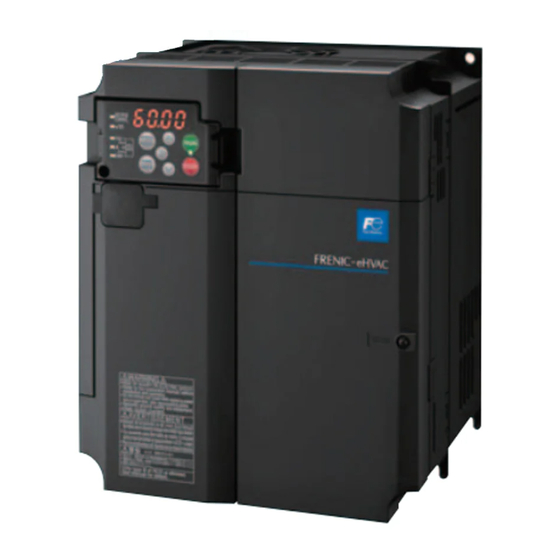
FRENIC-eHVAC
Fuji Electric FRENIC-eHVAC Manuals
Manuals and User Guides for Fuji Electric FRENIC-eHVAC. We have
1
Fuji Electric FRENIC-eHVAC manual available for free PDF download: User Manual
Fuji Electric FRENIC-eHVAC User Manual (631 pages)
Brand:
Fuji Electric
| Category:
Inverter
| Size: 26 MB
Table of Contents
Table of Contents
7
Acceptance Inspection (Nameplates and Inverter Type)
21
External View and Terminal Blocks
23
Precautions for Using Inverters
25
Usage Environment
25
Storage Environment
27
1 ] Temporary Storage
27
2 ] Long-Term Storage
27
Precautions for Connection of Peripheral Equipment
28
1 ] Phase-Advancing Capacitors for Power Factor Correction
28
2 ] Power Supply Lines (Application of a DC/AC Reactor)
28
3 ] DC Reactor (DCR) for Correcting the Inverter Input Power Factor (for Suppressing Harmonics)
28
4 ] PWM Converter for Correcting the Inverter Input Power Factor
28
3 ] DC Reactor (DCR) for Correcting the Inverter Input Power Factor
28
(For Suppressing Harmonics)
28
5 ] Molded Case Circuit Breaker (MCCB) / Residual-Current-Operated Protective Device (RCD) / Earth Leakage Circuit Breaker (ELCB)
29
6 ] Magnetic Contactor (MC) in the Inverter Input (Primary) Circuit
29
7 ] Magnetic Contactor (MC) in the Inverter Output (Secondary) Circuit
29
8 ] Surge Absorber/Surge Killer
29
Noise Reduction
30
Leakage Current
30
Precautions in Driving a Permanent Magnet Synchronous Motor (PMSM)
30
Installation
33
Wiring
35
Basic Connection Diagram
35
Removal and Attachment of the Front Cover/ Terminal Cover and Wiring Guide
37
Precautions for Wiring
40
Precautions for Long Wiring (between Inverter and Motor)
42
Main Circuit Terminals
44
1 ] Screw Specifications
44
2 ] Terminal Layout Diagram (Main Circuit Terminal)
45
3 ] Recommended Wire Size (Main Circuit Terminals)
46
4 ] Description of Terminal Functions (Main Circuit Terminal)
54
Control Circuit Terminals (Common to All Models)
58
1 ] Screw Specifications and Recommended Wire Size (Control Circuit Terminals)
58
2 ] Terminal Layout Diagram (Control Circuit Terminal)
58
Description of Terminal Functions (Control Circuit Terminal)
59
Switching Connector (Types FRN0176F2E-4G or Above)
67
Operating Slide Switches
70
Names and Functions of Keypad Components
75
Overview of Operation Modes
77
Running Mode
79
Monitoring the Running Status
79
Monitoring Light Alarms
81
Running or Stopping the Motor
82
Setting up Reference Frequency from the Keypad
83
Setting up PID Commands from the Keypad
84
1 ] Settings under PID Process Control
84
2 ] Settings under External PID Control
86
Remote and Local Modes
87
Programming Mode
88
Setting up Function Codes "Data Setting: !F
89
Setting up Function Codes "Data Setting
89
Checking Changed Function Codes "Data Checking: "Rep
90
Checking Changed Function Codes "Data Checking
90
Monitoring the Running Status "Drive Monitoring: #Ope
91
Monitoring the Running Status "Drive Monitoring
91
Checking I/O Signal Status "I/O Checking: $I_O
95
Checking I/O Signal Status "I/O Checking
95
Reading Maintenance Information "Maintenance Information: %Che
99
Reading Maintenance Information "Maintenance Information
99
Reading Alarm Information "Alarm Information
103
Copying Data "Data Copying: 'Cpy
106
Copying Data "Data Copying
106
Setting up Basic Function Codes Quickly "Quick Setup: *Fnc
110
Setting up Basic Function Codes Quickly "Quick Setup
110
Alarm Mode
112
Releasing the Alarm and Switching to Running Mode
112
Displaying the Alarm History
112
Displaying the Status of Inverter at the Time of Alarm
112
Switching to Programming Mode
112
Test Run Procedure Flowchart
115
Checking Prior to Powering on
116
Powering on and Checking
117
Selecting a Desired Motor Drive Control
118
V/F Control with Slip Compensation Inactive for IM
118
Vector Control Without Speed Sensor and Magnetic Pole Position Sensor for PMSM
118
Configuring Function Codes for Drive Controls
119
Driving an Induction Motor (IM)
120
1 ] Driving a Non-Fuji Motor or Fuji Non-Standard IM under the V/F Control
120
2 ] Driving a Fuji General-Purpose IM under the V/F Control
121
3 ] Tuning (for IM)
122
Driving a Permanent Magnet Synchronous Motor (PMSM) Without Pole Sensor and Magnetic Pole Position Sensor
125
1 ] Driving a Non-Fuji PMSM
125
Driving a Permanent Magnet Synchronous Motor (PMSM) Without Pole Sensor
125
And Magnetic Pole Position Sensor
125
2 ] Driving a Fuji Dedicated PMSM (GNB2 Series)
130
3 ] Driving a Fuji Non-Dedicated PMSM (Non-GNB2 Series)
130
Running the Inverter for Motor Operation Check
131
Test Run Procedure
131
Check Points During a Test Run
131
Modification of Motor Control Function Code Data
132
Selecting a Frequency Command Source
133
Setting up a Frequency Command from the Keypad
133
Setting up a Frequency Command with an External Potentiometer
133
Setting up a Frequency Command with Multistep Frequency Selection
134
Selecting a Run Command Source
135
Setting up a Run Command from the Keypad
135
Setting up a Run Command with Digital Input Signals (Terminals [FWD] and [REV])
135
Function Codes Overview
139
Function Codes Table
140
Supplementary Note
140
Function Codes Table
141
Function Codes Table
142
Factory Default Value Per Applicable Electric Motor Capacitance
169
Motor Constants
170
1 ] When Fuji Standard Motor 8-Series, or Other Motors Are Selected by Motor Selection (Function Code P99 = 0 or 4)
170
(Function Code P99 = 0 or 4)
170
2 ] When HP Rating Motor Is Selected by Motor Selection (Function Code P99/A39 = 1)
171
Description of Function Codes
172
F Codes (Basic Functions)
172
1 ] Frequency Setting by Keypad (F01 = 0 (Factory Default State), 8)
174
2 ] Setting up a Reference Frequency Using Analog Input (F01 = 1 to 3, 5)
175
3 ] Frequency Setting by Digital Input Signal "UP"/"DOWN" (F01=7)
181
4 ] Frequency Setting Using Pulse Train Input (F01=12)
182
E Codes (Extension Terminal Functions)
218
C Codes (Control Functions)
254
P Codes (Motor 1 Parameters)
263
H Codes (High Performance Functions)
268
1 ] Measuring the Capacitance of DC Link Bus Capacitor in Comparison with Initial One at Shipment
280
At Shipment
280
2 ] Measuring the Capacitance of DC Link Bus Capacitor under Ordinary Operating Conditions at Power Shutdown
281
A Codes (Motor 2 Parameters)
298
J Codes (Applied Functions)
299
1 ] PID Command with the / Keys on the Keypad (J02 = 0, Factory Default)
300
2 ] PID Command by Analog Inputs (J02 = 1)
300
3 ] PID Command with UP/DOWN Control (J02 = 3)
303
4 ] PID Command Via Communications Link (J02 = 4)
303
5 ] Pump Control
314
D Codes (Applied Functions 2)
366
1 ] Speed Control (Vector Control Without Speed Sensor nor Pole Position Sensor for PMSM)
366
U Codes (Customizable Logic Operation)
370
U1 Codes (Customizable Logic Operation)
395
Y Codes (Link Functions)
399
Protective Function
407
Before Proceeding with Troubleshooting
408
If an Alarm Code Appears on the LED Monitor
409
Alarm Code List
409
If an Alarm Code Appears on the LED Monitor
410
Causes, Checks and Measures of Alarms
412
Dba Braking Transistor Broken
412
Dbh Braking Resistor Overheat
412
1 ] PID Feedback Wire Break
412
Ecl Customizable Logic Failure
413
5 ] Ef Ground Fault
413
Ef Ground Fault
413
6 ] Er1 Memory Error
413
Er1 Memory Error
413
5 ] Ground Fault
413
7 ] Er2 Keypad Communications Error
414
8 ] Er3 CPU Error
414
Er3 CPU Error
414
9 ] Er4 Option Communications Error
414
10 ] Er5 Option Error
414
Er5 Option Error
414
11 ] Er6 Operation Error
415
Er6 Operation Error
415
12 ] Er7 Tuning Error
415
Er7 Tuning Error
415
13 ] Er8
416
Communications Error (Communications Port 1)/ Erp RS-485 Communications Error (Communications Port 2)
416
Erd Step-Out Detection/Detection Failure of Magnetic Pole Position at Startup
417
14 ] Erd Step-Out Detection/Detection Failure of Magnetic Pole Position at Startup
417
Ere Speed Inconsistency / Excessive Speed Deviation
418
15 ] Ere Speed Inconsistency / Excessive Speed Deviation
418
Erf Data Saving Error During Undervoltage
419
Erh Hardware Error
419
Err Simulated Failure
419
Fus DC Fuse-Blowing
419
Lin Input Phase Loss
420
Lok Password Protection
420
22 ] Lu Undervoltage
421
Lu Undervoltage
421
23 ] 0Cn Instantaneous Overcurrent
422
Cooling Fin Overheat
423
25 ] 0H2 External Alarm
423
26 ] 0H3 Inverter Internal Overheat
423
25 ] 0H2
423
External Alarm
423
26 ] 0H3
423
Inverter Internal Overheat
423
Motor Protection (PTC Thermistor)
424
28 ] 0H6 Charging Resistor Overheat
424
27 ] 0H4
424
28 ] 0H6
424
Charging Resistor Overheat
424
Motor Overloads 1
425
29 ] 0L1
425
30 ] 0Lu Inverter Overload
426
31 ] 0Pl Output Phase-Failure Detection
426
30 ] 0Lu
426
Inverter Overload
426
31 ] 0Pl
426
Output Phase-Failure Detection
426
32 ] 0S Overspeed Protection
427
33 ] 0Un Overvoltage
427
32 ] 0S
427
Overspeed Protection
427
0Un Overvoltage
427
Pbf Charge Circuit Fault
428
If the "Light Alarm" Indication ( L-Al ) Appears on the LED Monitor
429
If the "Light Alarm" Indication
429
Appears on the LED Monitor
429
When Codes Other than Alarm Codes and Light Alarm Indication ( L-Al ) Are Displayed
430
Abnormal Motor Operation
430
1 ] the Motor Does Not Rotate
430
When Codes Other than Alarm Codes and Light Alarm Indication
430
2 ] the Motor Rotates, but the Speed Does Not Increase
432
3 ] the Motor Runs in the Opposite Direction to the Command
433
4 ] Speed Fluctuation or Current Oscillation (E.g., Hunting) Occurs During Running at Constant Speed
434
5 ] Unpleasant Noises Are Emitted from Motor or Noises Fluctuate
435
6 ] Motor Is Not Accelerated or Decelerated According to Set-Up Acceleration or Deceleration Times
435
7 ] the Motor Does Not Restart Even after the Power Recovers from a Momentary Power Failure
436
8 ] Motor Generates Heat Abnormally
436
9 ] the Motor Does Not Run as Expected
436
10 ] Motor Stalls During Acceleration
437
Problems with Inverter Settings
438
1 ] Nothing Appears on the LED Monitor
438
2 ] the Desired Menu Is Not Displayed
438
3 ] Display of under Bars
439
4 ] Display of Center Bars
439
5 ] C ] Display of Parenthesis
439
Display of Parenthesis
439
6 ] Data of Function Codes Cannot be Changed
440
7 ] Function Code Data Are Not Changeable (Change from Link Functions)
440
Inspection Interval
443
Daily Inspection
444
Periodic Inspection
445
Periodic Inspection 1--Before the Inverter Is Powered on or after It Stops Running
445
Periodic Inspection 2--When the Inverter Is on or It Is Running
446
List of Periodic Replacement Parts
447
Judgment on Service Life
448
1 ] Measuring the Capacitance of DC Link Bus Capacitor in Comparison with Initial One at Shipment
449
2 ] Measuring the Capacitance of the DC Link Bus Capacitor under Ordinary Operating Conditions
450
3 ] Early Warning of Lifetime Alarm
450
Measurement of Electrical Amounts in Main Circuit
451
Insulation Test
452
Inquiries about Product and Guarantee
453
When Making an Inquiry
453
Product Warranty
453
1 ] Free of Charge Warranty Period and Warranty Range
453
2 ] Exclusion of Liability for Loss of Opportunity, Etc
454
3 ] Repair Period after Production Stop, Spare Parts Supply Period (Holding Period)
454
4 ] Transfer Rights
454
5 ] Service Contents
454
6 ] Applicable Scope of Service
454
Meanings of Symbols Used in the Control Block Diagrams
457
Frequency Setting Section
458
Operation Command Section
461
PID Control Section (for Processing)
462
PID Control Section (External PID)
463
Control Section
464
V/F Control
464
1 ] Common
464
2 ] V/F Control
465
Vector Control
466
1 ] Common
466
2 ] Torque Limit
466
3 ] Speed Limit and over Speed Protection Processing
467
4 ] for PMSM
468
FM Output Section
470
Overview of RS-485 Communication
473
Common Specifications
474
Terminal Specifications
475
Communication Port 1 (for Connecting the Keypad)
475
Communication Port 2 (Terminal Block)
475
Connection Method
476
Connection Devices
478
1 ] Converter
478
2 ] Requirements for the Cable (COM Port 1: for RJ-45 Connector)
479
3 ] Requirements for the Cable (COM Port 2: for RS-485 Connector)
479
4 ] Branch Adapter for Multi-Drop
479
Noise Suppression
479
FRENIC Loader Overview
480
Modes
480
Connection
481
Function Overview
481
1 ] Configuring Inverter's Function Code
481
2 ] Multi-Monitor
482
3 ] Running Status Monitor
483
4 ] Test-Running
484
5 ] Real-Time Trace
485
Historical Trace
486
Motor Output Torque Characteristics
489
Selection Procedure
491
Equations for Selections
494
Load Torque During Constant Speed Running
494
1 ] General Equation
494
2 ] Obtaining the Required Force F
494
Acceleration and Deceleration Time Calculation
496
1 ] Calculation of Moment of Inertia
496
2 ] Calculation of the Acceleration Time
498
3 ] Calculation of the Deceleration Time
499
4 ] Calculating Non-Linear Acceleration/Deceleration Time
499
5 ] Calculating Non-Linear Deceleration Time
500
Heat Energy Calculation of Braking Resistor
501
1 ] Calculation of Regenerative Energy
501
Calculating the RMS Rating of the Motor
502
Selecting an Inverter Drive Mode
503
Precaution in Making the Selection
503
Configuring the FRENIC-Ehvac
507
Currents Flowing Across the Inverter Terminals
508
Molded Case Circuit Breaker (MCCB), Residual-Current-Operated Protective Device (Rcd)/Earth Leakage Circuit Breaker (ELCB) and Magnetic Contactor (MC)
509
Function Overview
509
Connection Example and Criteria for Selection of Circuit Breakers
510
Surge Killers for L-Load
513
Arresters
514
Surge Absorbers
515
Filtering Capacitors Suppressing am Radio Band Noises
516
Braking Resistors (Dbrs) and Braking Units
517
Selecting a Braking Resistor
517
1 ] Selection Procedure
517
2 ] Notes on Selection
517
Braking Resistors (Dbrs)
518
1 ] Standard Model
518
2 ] 10%ED Model
518
Braking Units
519
Specifications
520
External Dimensions
522
Power Regenerative PWM Converters, RHC Series
524
Overview
524
Specifications
525
1 ] Standard Specifications
525
2 ] Common Specifications
526
Function Specifications
527
Converter Configuration
531
External Dimensions
533
DC Reactors (Dcrs)
538
AC Reactors (Acrs)
541
Surge Suppression Unit (SSU)
543
Output Circuit Filters (Ofls)
544
Zero-Phase Reactors for Reducing Radio Noise (Acls)
546
External Cooling Fan Attachments
547
External Frequency Command Potentiometer
548
Extension Cable for Remote Operation
549
Frequency Meters
550
Options for Communication and Operation Overview
551
Mounting Adapter ( for Communication Option Card)
551
Communication Option Cards (Required Mounting Adapter Required)
551
Terminal Block Type Options
551
Option Keypad
551
Devicenet Communications Card (OPC-DEV)
552
Devicenet Specifications
552
CC-Link Communications Card (OPC-CCL)
553
CC-Link Specifications
553
Analog Interface Card (OPC-AIO)
554
RTD Card (OPC-PT)
557
Lonworks Card (OPC-LNW)
558
Relay Output Card (OPC-F2-RY)
559
Simple Keypad with USB Port (TP-E1U)
560
Multi Functional Keypad (TP-A1)
561
FRENIC Visual Customizer
562
Overview
562
Specifications
562
Functions
562
Main Window
563
Standard Model
567
Inverters for General Load
567
Common Specifications
570
Standard Model
576
Appendices
591
Appendix A Trouble-Free Use of Inverters (Notes on Electrical Noise)
593
Effect of Inverters on Other Devices
593
Effect on am Radios
593
Effect on Telephones
593
Effect on Proximity Switches
593
Effect on Pressure Sensors
593
Effect on Position Detectors (Pulse Encoders)
593
Noise
594
1 ] Inverter Noise
594
2 ] Types of Noise
595
Measures
597
1 ] Noise Prevention Prior to Installation
597
2 ] Implementation of Noise Prevention Measures
597
3 ] Noise Prevention Examples
600
Appendix B Japanese Guideline for Suppressing Harmonics by Customers Receiving High Voltage or Special High Voltage (General-Purpose Inverter)
604
Application to General-Purpose Inverters
604
1 ] Guideline for Suppressing Harmonics in Home Electric and General-Purpose Appliances
604
2 ] Guideline for Suppressing Harmonics by Customers Receiving High Voltage or Special High Voltage
604
1 ] Guideline for Suppressing Harmonics in Home Electric and General-Purpose
604
Appliances
604
2 ] Guideline for Suppressing Harmonics by Customers Receiving High Voltage or
604
Special High Voltage
604
Compliance to the Harmonic Suppression for Customers Receiving High Voltage or Special High Voltage
605
1 ] Calculation of Equivalent Capacity (Pi)
605
Compliance to the Harmonic Suppression for Customers Receiving High Voltage or
605
2 ] Calculation of Harmonic Current
606
3 ] Examples of Calculation
608
Appendix C Effect on Insulation of General-Purpose Motors Driven with 400 V Class Inverters
609
Generating Mechanism of Surge Voltages
609
Effect of Surge Voltages
610
Countermeasures against Surge Voltages
611
1 ] Using a Surge Suppressor Unit, SSU (Patent Pending)
611
2 ] Suppressing Surge Voltages
611
3 ] Using Motors with Enhanced Insulation
611
Regarding Existing Equipment
612
1 ] in Case of a Motor Being Driven with 400 V Class Inverter
612
2 ] in Case of an Existing Motor Driven Using a Newly Installed 400 V Class Inverter
612
Appendix D Inverter Generating Loss
613
Appendix E Conversion from si Units
614
Conversion of Units
614
Calculation Formulas
615
Appendix F Allowable Current of Insulated Wires
616
Appendix G Conformity with Standards
618
Compliance with European Standards
618
1 ] Compliance with EMC Standards
618
Compliance with the Low Voltage Directive in the EU
621
Compliance with UL Standards and Canadian Standards (Cul Certification) ( )
624
Appendix H Compliance with Management Methods for Controlling Pollution Caused by Electronic Information Products Regulation (China Rohs)
628
Advertisement
Advertisement
Related Products
Fuji Electric FRENIC-Eco Series
Fuji Electric Frenic Eco Series
Fuji Electric FRENIC-Multi
Fuji Electric FRENIC-Lift series
Fuji Electric FRENIC-Multi Series
Fuji Electric FRENIC-Ace series
Fuji Electric frenic-hvac
Fuji Electric FRENIC5000G11S Series
Fuji Electric FRENIC5000P11S Series
Fuji Electric Frenic-Sce
Fuji Electric Categories
Air Conditioner
Inverter
Measuring Instruments
Controller
Control Unit
More Fuji Electric Manuals
Login
Sign In
OR
Sign in with Facebook
Sign in with Google
Upload manual
Upload from disk
Upload from URL