Sign In
Upload
Manuals
Brands
Fronius Manuals
Welding System
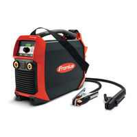
TransPocket 1500
Fronius TransPocket 1500 Manuals
Manuals and User Guides for Fronius TransPocket 1500. We have
2
Fronius TransPocket 1500 manuals available for free PDF download: Operating Instructions Manual, Service Manual
Fronius TransPocket 1500 Service Manual (117 pages)
Brand:
Fronius
| Category:
Welding System
| Size: 5 MB
Table of Contents
Service Manual
1
Dear Service Technician
2
General Remarks
2
Safety
2
Table of Contents
3
Safety Rules
7
General Remarks
7
Utilisation for Intended Purpose Only
8
Ambient Conditions
8
Obligations of Owner/Operator
8
Obligations of Personnel
8
Personal Protective Equipment
9
Hazards from Noxious Gases and Vapours
9
Hazards from Flying Sparks
9
Hazards from Mains and Welding Current
10
Hazards When the Machine Housing Is Open
10
Vagrant Welding Currents
10
EMC Precautions
11
Particular Danger Spots
11
Informal Safety Precautions
12
Safety Precautions at the Installation Location
12
Safety Precautions in Normal Operation
12
Safety Inspection
12
Alterations to the Power Source
13
Spares and Wearing Parts
13
Calibration of Power Sources
13
CE-Marking
13
Copyright
13
Technical Data - Rating Plate
14
Rating Plate
14
Identification
14
Data Regarding Weld Process
14
Duty Cycle
15
Data Regarding Power Supply
16
Standard Characteristic
16
Set-Up Regulations
17
Mains Connection
17
General Basics - Functional Principle
18
Inverter Principle - General Remarks
18
Resonance Converter
18
Series Resonance Converter
19
Series-Parallel Resonance Converter
19
Increasing the Output Voltage by Means of Series-Parallel Resonance
20
Limiting the Increased Output Voltage in Open Circuit
20
Complex Regulation
20
Applying the Resonance Converter Principle
21
Measuring and Regulating the Parameters "Welding Current" and "Welding Voltage
21
Hot-Start and Anti-Stick Functions
22
TIG-Comfort-Stop" Function
24
Gas Flow
25
VRD - Voltage Reduction Device
25
General Basics - How to Handle Components
27
ESD Precautions
27
Heat Dissipation from Power Componentry
28
General Basics - Packaging
30
Delivery
30
History
31
Modification
31
Measuring and Testing Equipment, Tools
31
General Remarks
31
Measuring and Test Equipment
31
Tools and Appliances
31
Additional Needed Tools
32
Filter Attachment
32
Filter Attachment with Filter Insert
32
Opening the Housing
33
Care and Maintenance
33
Regular Checks and Care
33
Checking and Setting the Maximum Welding Amperage
33
Troubleshooting
34
Safety
34
Troubleshooting Table
34
Measuring, Inspection and Adjustment Jobs - Checking and Setting the Parameters on the Welding Sockets
38
General Remarks
38
Checking the Maximum Welding Amperage and Hot-Start
38
Setting the Maximum Welding Amperage
38
Checking the Minimum Welding Amperage
39
Checking the Open-Circuit Voltage
40
Checking the Open-Circuit Voltage - TP 1500 VRD
41
Check the Arc-Force and Anti-Stick
41
Cycle Test
42
Checking the Transistor Module
44
Checking the Secondary Diode
48
Checking the Potentiometer Ribbon Cable
49
PE Conductor Test
49
Insulation Test
50
Maintenance and Repair Work
52
Installation Instructions
52
Overall Circuit Diagram
53
Installation Instructions: LCG15 Board and Secondary Diode
55
Safety
55
Scope of Supply
55
Tools Needed
55
Opening the Housing
55
Removing the LCG15 Board
56
Removing the Secondary Diode
57
Fitting the Secondary Diode
58
Fitting the LCG15 Board - Secondary Diode with Two Cup Springs
59
Fitting the LCG15 Board - Secondary Diode with Four Cup Springs
59
Mounting the Shunt and Connecting the Leads
60
Closing the Housing
61
Installation Instructions: LCA15 Board
62
Safety
62
Scope of Supply
62
Tools Needed
62
Additional Tools Needed
62
Opening the Housing
62
Removing the LCA15 Board
63
Fitting the LCA15 Board
64
Closing the Housing
68
Installation Instructions: FPA15 Board
69
Safety
69
Scope of Supply
69
Tools Needed
69
Additional Tools Needed
69
Opening the Housing
69
Removing the FPA15 Board
70
Fitting the FPA15 Board
71
Closing the Housing
73
Installation Instructions: Varistor
74
Safety
74
Scope of Supply
74
Tools Needed
74
Opening the Housing
74
Removing the Varistor
75
Fitting the Varistor
76
Closing the Housing
76
Installation Instructions: Transformer
77
Safety
77
Scope of Supply
77
Tools Needed
77
Additional Tools Needed
77
Opening the Housing
77
Removing the LCA15 Board
78
Removing the Transformer
79
Fitting the Transformer
80
Fitting the LCA15 Board
80
Closing the Housing
84
Installation Instructions: Temperature Sensor
85
Safety
85
Scope of Supply
85
Tools Needed
85
Opening the Housing
85
Removing the Temperature Sensor
86
Fitting the Temperature Sensor
86
Closing the Housing
87
Installation Instructions: Fan
88
Safety
88
Scope of Supply
88
Tools Needed
88
Opening the Housing
88
Removing the Fan
89
Fitting the Fan
90
Closing the Housing
91
Installation Instructions: Mains Switch and Mains Cable
92
Safety
92
General Remarks
92
Scope of Supply
92
Tools Needed
92
Opening the Housing
92
Unplugging the Mains Leads
93
Removing the Mains Switch
93
Removing the Mains Cable
94
Mounting the Mains Cable
95
Fitting the Mains Switch
96
Plugging on the Mains Leads
96
Closing the Housing
96
Installation Instructions: Gas Solenoid Valve
97
Safety
97
Scope of Supply
97
Opening the Housing
97
Removing the Gas Solenoid Valve
98
Fitting the Gas Solenoid Valve
98
Closing the Housing
99
Installation Instructions: Potentiometer, Connection Socket + Seal for Remote Control Unit
100
Safety
100
General Remarks
100
Scope of Supply
100
Tools Needed
100
Additional Needed Tools
100
Opening the Housing
101
Removing the FPA15 Board
101
Removing the Seal for the Remote-Control Unit Connection Socket
103
Removing the Potentiometer and Remote-Control Unit Connection Socket
103
Fitting the Potentiometer and Remote-Control Unit Connection Socket
103
Fitting the Seal for the Remote-Control Unit Connection Socket
104
Fitting the FPA15 Board
104
Closing the Housing
105
Installation Instructions: Front of Housing, with Adhesive Label and Welding Sockets
106
Safety
106
General Remarks
106
Scope of Supply
106
Tools Needed
106
Opening the Housing
107
Removing the FPA15 Board
107
Removing the Seal for the Remote-Control Unit Connection Socket
108
Removing the Welding Sockets
109
Removing the Front of the Housing
109
Fitting the Front of the Housing
110
Fitting the Welding Sockets
110
Fitting the Seal for the Remote-Control Unit Connection Socket
111
Fitting the FPA15 Board
112
Closing the Housing
113
Advertisement
Fronius TransPocket 1500 Operating Instructions Manual (127 pages)
Brand:
Fronius
| Category:
Welding System
| Size: 8 MB
Table of Contents
Deutsch
17
Table of Contents
17
Allgemeines
19
Prinzip
19
Gerätekonzept
20
Allgemeines
20
Tp 1500 Tig
20
Vrd
21
Einsatzgebiete
21
Stabelektroden-Schweißen
21
WIG-Schweißen
21
Bedienelemente und Anschlüsse
22
Sicherheit
22
Stromquelle
22
Vor der Inbetriebnahme
24
Sicherheit
24
Bestimmungsgemässe Verwendung
24
Aufstellbestimmungen
24
Netzanschluss
24
Stabelektroden-Schweißen
25
Sicherheit
25
Vorbereiten
25
Verfahren Anwählen
25
Schweißstrom Einstellen, Lichtbogen Zünden
26
Funktion Hot-Start
26
Funktion Anti-Stick
26
WIG-Schweißen
27
Sicherheit
27
Allgemeines
27
Vorbereiten
27
Schutzgasmenge Einstellen
28
Verfahren Anwählen
28
Schweißstrom Einstellen, Lichtbogen Zünden
28
Funktion TIG-Comfort-Stop
30
Das Setup-Menü
32
Einstellmöglichkeiten
32
Funktionsprinzip
32
Parameter Einstellen
32
Parameter Dynamik (für das Verfahren Stabelektroden-Schweißen)
33
Parameter TIG-Comfort-Stop (für das Verfahren WIG-Schweissen)
34
Tabelle Werkseinstellung für Parameter
35
Generatorbetrieb
35
Anforderungen
35
Pflege, Wartung und Entsorgung
36
Allgemeines
36
Bei jeder Inbetriebnahme
36
Alle 2 Monate
36
Alle 6 Monate
36
Entsorgung
36
Technische Daten
37
Sicherheit
37
Tp 1500, Tp 1500 Vrd, Tp 1500 Rc, Tp 1500 Tig, Tp 1500 Tig Vrd
37
English
57
General Remarks
59
Principle of the TP 1500
59
Machine Concept
60
General Remarks
60
Tp 1500 Tig
60
Vrd
61
Areas of Use
61
Electrode Welding
61
TIG Welding
61
Controls and Connections
62
Safety
62
Power Source
62
Before Putting the Power Source into Service
64
Safety
64
Utilisation for Intended Purpose Only
64
Machine Set-Up Regulations
64
Mains Connection
64
Rod Electrode Welding
65
Safety
65
Preparation
65
Select Process
65
Set the Welding Amperage, Ignite the Arc
66
Funktion Hot-Start
66
Anti-Stick Function
66
TIG Welding
67
Safety
67
General
67
Preparation
67
Setting the Gas-Flow Rate
68
Selecting the Process
68
Setting the Welding Amperage, Igniting the Arc
68
TIG Comfort-Stop Function
69
The Set-Up Menu
72
Possible Settings and Adjustments
72
Function Principle
72
Arc Force" Parameter (for the Rod-Electrode Welding Process)
73
Characteristic" Parameter (for the Rod-Electrode Welding Process with CEL Electrodes)
73
TIG Comfort-Stop Parameter (for the TIG Welding Process)
74
Table of Factory Settings for Parameters
75
Generator-Powered Operation
75
Requirements
75
Care, Maintenance and Disposal
76
General Remarks
76
Every Start-Up
76
Every 2 Months
76
Every 6 Months
76
Disposal
76
Technical Data
77
Tp 1500, Tp 1500 Vrd, Tp 1500 Rc, Tp 1500 Tig, Tp 1500 Tig Vrd
77
Tp 1500 Vrd, Tp 1500 Tig Vrd
78
General Remarks
78
Safety Principle of the TP 1500 VRD and TP 1500 TIG VRD
78
Warning Indicators When the Voltage Limitation Is no Longer Active
78
Troubleshooting
79
Safety
79
Troubleshooting TP 1500, TP 1500 RC, TP 1500 TIG
80
Français
97
Généralités
99
Principe
99
Construction de L'appareil
100
Généralités
100
Tp 1500 Tig
100
Vrd
101
Champs D'application
101
Soudage TIG
101
Eléments de Réglage Et Raccords
102
Securité
102
Source de Courant
103
Avant la Mise en Service
104
Securité
104
Utilisation Conforme À la Destination Prévue
104
Consignes Concernant L'installation
104
Raccordement Au Secteur
104
Soudage À la Baguette
105
Securité
105
Préparatifs
105
Sélection du ProcéDé de Soudage
105
Régler Le Courant de Soudage, Amorcer L'arc Électrique
106
Fonction "Hot Start
106
Fonction Anti-Stick
106
Soudage TIG
107
Securité
107
Généralités
107
Préparatifs
107
Régler la Quantité de Gaz Protecteur
108
Sélectionner Le ProcéDé
108
Régler Le Courant de Soudage, Amorcer L'arc Électrique
108
Fonction "Arrêt Confort TIG
110
Le Menu Setup
112
Possibilités de Réglage
112
Principe de Fonctionnement
112
Régler Les Paramètres
112
Paramètre Dynamique (Pour Le Soudage À la Baguette)
113
Paramètre Arrêt Confort TIG (Pour Le Soudage TIG)
114
Tableau des Réglages Usine des Paramètres
115
Service Avec Générateur
115
Exigences
115
Maintenance, Entretien Et Élimination
116
Généralités
116
Tous Le 2 Mois
116
Tous Les 6 Mois
116
Élimination
116
Données Techniques
117
Tp 1500, Tp 1500 Vrd, Tp 1500 Rc, Tp 1500 Tig, Tp 1500 Tig Vrd
117
Tp 1500 Vrd, Tp 1500 Tig Vrd
118
Généralités
118
Principe de Sécurité TP 1500 VRD, TP 1500 TIG VRD
118
Affichage en Cas de Disparition de la Limitation de Tension
118
Pannes: Diagnostic Et Remèdes
119
Securité
119
Liste de Pièces de Rechange
123
Schema de Connexions
123
Advertisement
Related Products
Fronius TransPocket 150
Fronius AccuPocket 150/400
Fronius TransPocket 1500 VRD
Fronius TransPocket 1500 RC
Fronius TransPocket 1500 TIG
Fronius AccuPocket 150/400 TIG
Fronius TransPocket 180
Fronius TransTig 1750 Puls
Fronius MagicWave 1700
Fronius DeltaSpot GunControl 110/230
Fronius Categories
Inverter
Welding System
Welding Accessories
Battery Charger
Measuring Instruments
More Fronius Manuals
Login
Sign In
OR
Sign in with Facebook
Sign in with Google
Upload manual
Upload from disk
Upload from URL