Sign In
Upload
Manuals
Brands
Festo Manuals
Control Systems
CMXR-C1
Festo CMXR-C1 Multi-axis controllers Manuals
Manuals and User Guides for Festo CMXR-C1 Multi-axis controllers. We have
5
Festo CMXR-C1 Multi-axis controllers manuals available for free PDF download: Programming Instructions Manual, System Manual, Assembly And Installation Manual, Description
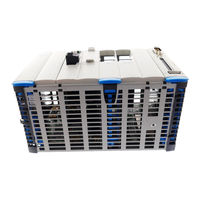
Festo CMXR-C1 Programming Instructions Manual (192 pages)
Brand:
Festo
| Category:
Controller
| Size: 5.64 MB
Table of Contents
Table of Contents
5
1 Introduction
11
2 Safety Precautions
12
Using the Documentation
12
Recommended Operating Conditions
12
Qualified Personnel
13
Safety Notes on the Products
13
Safety Notes on this Manual
13
Safety Instructions for the Described Product
14
3 Program Processing
15
General Information
15
Interpreter
15
Program Start
15
Set Forerun
15
Program Structure
17
FTL Projects
17
Global FTL Project
18
FTL Program File "Tip
18
Project-Global Programs
19
FTL Data File "<Name>.Tid
19
Local Program Data
19
Project-Global Data
20
System-Global Data
20
Instancing of Variables
21
4 Language Set-Up
23
Formatting
23
Identifiers
23
Keywords
23
Numeric Constants
24
Strings
24
Operators and Limiting Characters
24
Arithmetical Operators
24
Logical Operators
25
Comparators
25
Other Operators
25
Limiting Characters
26
5 Master Data Types
27
Boolean Data Type (BOOL)
28
Integer Types, REAL Data Type, Bit Pattern Types
28
Strings
29
Structured Data Types
29
Arrays
29
6 Declaration of Variables
30
Initialisation
30
7 Statements
31
Execution Sequence in Statements
31
8 Program Control
32
Instructions
32
Value Assignment
32
Conditions
32
Branching <IF
34
Jump Commands
35
Jump Label <LABEL
35
Conditional Jump <IF
36
Absolute Jump <GOTO
36
Loops
36
WHILE Instruction <WHILE
37
LOOP Instruction <LOOP
37
Subprograms
38
Subprogram Call-Up <CALL
39
Program Return <RETURN
40
Parallel Programs
41
Starting the Parallel Program <RUN
42
Stopping the Parallel Program <KILL
42
WAIT - Instruction with Time <Waittime
42
WAIT Instruction with Condition <WAIT
43
Adding Comments
46
Deactivating the Program Line
46
9 Movement Commands
48
Positional Description
48
Axis Position
48
Cartesian Position
51
Point-To-Point Movement <Ptp
52
Relative Point-To-Point Movement <Ptprel
55
Movement of an Axis, <Moveaxisptp>, <Moveaxiscart
57
Linear Motion <Lin
59
Relative Linear Motion <Linrel
61
Circular Movement with Support Point
63
Method of Operation
63
Definition of Levels
64
Circular Command with Support Point <Circip
66
Circular Command with Support Point, PTP Travel <Ptptocircip
68
Circular Command with Support Point, Lin Travel <Lintocircip
70
Stopping the Movement <Stopmove
71
10 Dynamics Commands
72
Speeds <Vel
72
Acceleration <Acc
73
Jerk <Jerk
74
Override
76
Override on the Teach Pendant <Ovr
76
Dynamic Override <Dynovr
77
Acceleration Ramps
78
Setting the Ramp Forms <Ramp
79
Switching on Constant Path Speed <Vconston
80
Switching off Constant Path Speed <Vconstoff
82
11 Smooth-Transition Commands
83
Marginal Area
84
Speed-Type Smooth Transition
85
With the Percentage Factor <Ovlvel
85
Smooth Geometric Transition
87
Smooth Transition of Axes X, y and Z <Ovlcart
87
Reference Systems (Zero Offset)
89
Reference of the Reference System
89
Data for the Reference System
90
Reference System with Direct Values <Setrefsys
91
Reference System with Three Points <Setrefsys3P
92
World Reference System <Setrefsysworld
93
Example
94
12 Referencing a Kinematics System
96
Homing <Refaxis
96
Asynchronous Homing <Refaxisasync
98
Waiting for the End of the Homing Run <Waitreffinished
100
Interrogating Status of an Axis <Isaxisreferenced
101
13 Tools
102
Tool Data
102
Data for the TCP Vector
102
Activating Tool Data <Tool
105
Effect of TCP Data
105
14 PROFIBUS Interface
110
Boolean Inputs and Outputs
110
32-Bit Integer Variables
111
Positions
112
Reference Systems
113
Programmed Stop <Proghold
114
15 Message System
116
Message Texts
116
Information <Setinfo
118
Warning <Setwarning
119
Error Message <Seterror
120
16 Functions
121
Reading the Actual Position <Readactualpos
121
Reading the Target Position <Readtargetpos
122
Permanently Saving Position Value <Saveposition
123
Reading the System Time <Time
123
Converting Time into Text <Timetostr
124
Sine <SIN>, <ASIN
125
Cosine <COS>, <ACOS
126
Tangent <TAN>, <ATAN
128
Cotangent <COT>, <ACOT
129
Tangent2 <ATAN2
130
Logarithm <LN
130
Exponent <EXP
130
Absolute Value <ABS
131
Square Root <SQRT
131
Shifting Bit-By-Bit <SHR>, <SHL
132
Rotating Bit-By-Bit <ROR>, <ROL
133
17 Modules
134
Functions
135
Variables
135
Runtime Behaviour
136
Parameter Ovlenable
136
Digital Input Module DIN
137
Instancing
137
Methods
139
Waiting for the Status, Methods Wait / Waitn
140
Reading Status with Read Method
140
Risingedge Method
140
Resetrisingedge Method
141
Digital Output Module DOUT
141
Instancing
141
Variables
143
Methods
144
Waiting for the Status, Methods Wait / Waitn
145
Reading Status with Read Method
145
Risingedge Method
145
Resetrisingedge
146
Set / Reset Methods
146
Setting the Output, Write Method
147
Analogue Input Module AIN
147
Instancing
147
Variables
148
Methods
149
Waiting until the Value Is Less/Greater - Waitlss/Waitgrt Methods
150
Waiting until Value Is Inside/Outside the Range - Waitins/Waitouts Methods
150
Sensing the Value, Read Method
151
Analogue Output Module AOUT
152
Instancing
152
Variables
153
Methods
154
Writing the Output Value, Write Method
155
Waiting until the Value Is Greater/Less - Waitlss/Waitgrt Methods
155
Reading Output Value, Read Method
156
Timer Module CLOCK
157
Instancing
157
Methods
158
Starting the Timer, Start Method
158
Stopping the Timer, Stop Method
159
Resetting the Timer, Reset Method
159
Reading the Timer, Read Method
159
Converting Time Value into String
160
Encoder Module ENCODER
161
Instancing
161
Variables
162
Methods
162
Setting the Encoder, Set Method
163
Reading the Encoder, Read Method
163
Canopen Module COPDEVICE
164
Instancing
164
Methods
165
Writing SDO, Writesdo Method
165
Reading SDO, Readsdosigned Method
166
Reading SDO, Readsdounsigned Method
168
18 Peripheral Signals
169
Working with Digital Inputs and Outputs
169
Working with Analogue Inputs and Outputs
169
19 Examples
171
Stopping the Movements
171
Working with Input and Output Modules
174
Controlling the Set Forerun
175
Working with Grippers
176
Vacuum Grippers
177
Pneumatic Parallel Grippers
180
Pneumatic Swivel/Gripper Unit
183
Working with the PLC Interface
187
Problem Definition
187
PLC Interface
187
Sequence Program
188
Advertisement
Festo CMXR-C1 System Manual (88 pages)
Brand:
Festo
| Category:
Controller
| Size: 5.72 MB
Table of Contents
Table of Contents
5
1 Introduction
8
Terminology Used
8
2 Safety Instructions
9
Using the Documentation
9
Recommended Operating Conditions
9
Qualified Personnel
10
Safety Notes on this Manual
10
Safety Notes on the Products
10
Safety Instructions for the Described Product
11
3 Modular Multi-Axis Control System CMXR
13
Central Control Unit CMXR-C1
13
CAN Interfaces
14
Memory Card
15
File System
16
Application Directory
17
IP Address on Delivery
17
Peripheral Modules
18
Addressing the Peripheral Modules
19
Front Panel Plug
20
Peripherals at Interface CAN 1
21
4 Configuration Using FCT
22
5 Programming, Festo Teach Language (FTL)
23
Program Processing
24
Downloading FTL Programs
24
6 CDSA Teach Pendant
26
Installation
28
CAMI-C Interface Unit
29
Disconnecting the Teach Pendant
29
Hardware Overview
31
Software
31
User Rights
33
User Levels
34
Set Users on Delivery
36
Communication with the CMXR Multi-Axis Control System
36
Synchronisation of Dialogue Software
37
IP Addresses on Delivery
37
Screen Control
38
7 Drive Systems
39
Setting for Servo Configuration
39
CAN Bus Address for Motor Controllers
39
Homing Run
40
8 Operation Modes
41
Manual Override
41
Automatic Mode
42
Stopping the Kinematics, EMERGENCY-STOP
42
Repositioning
44
9 Activation Method
46
Operation Without External Control
46
System Signals
48
External Control Via the Digital I/O Interface
49
Functions of the I/O Interface
50
External Control Via PROFIBUS DP
51
System Signals
52
Functions of the PROFIBUS Interface
53
Interface for the FTL Program
53
Higher-Order Control
55
Method of Operation
55
User Level
56
Influence of the Higher-Order Control
56
Integration Example
57
10 Coordinate Systems
59
Axis Coordinate Systems
59
Cartesian Coordinate Systems
59
Translatory Axes X, Y, Z
59
Orientation Axes A, B, C
60
Euler Orientation ZYZ
61
Coordinate Systems for the Kinematics
61
Base Coordinate System
61
World Coordinate System
63
Tool Coordinate System
65
Working with the Tool Coordinate System
65
11 Supported Kinematics
67
Configuration of Kinematics
67
Basic Axes
67
Orientation Axes (Manual Axes)
68
Adjustment of Orientation Axes
68
Interpolation of Orientation Axes
70
Electric and Pneumatic Manual Axes
73
Auxiliary Axes
73
Programming the Manual and Auxiliary Axes
74
Designation of Axis Sequence for Kinematics
75
Cartesian Linear Gantry
75
Cartesian Planar Surface Gantry
78
Cartesian Three-Dimensional Gantry
79
Tripod Kinematics
82
Origin of the Tool Coordinate System
84
Axis Interpolation
85
Overview of All Supported Kinematics Systems
86
Festo CMXR-C1 Assembly And Installation Manual (68 pages)
Brand:
Festo
| Category:
Controller
| Size: 4.24 MB
Table of Contents
Table of Contents
5
Intended Use
7
Areas of Application and Approval by Authorities
8
Important User Instructions
8
Safety Precautions
11
Target Group
13
Service
13
Contents of this Manual
13
Documentation on the CMXR-C1 Control System
14
Required Software Versions
14
General Product-Specific Terms and Abbreviations
15
1 CMXR System Overview
16
Product Versions
16
Structure of the Device
18
Central Control Unit
18
Optional Modules
19
Peripheral Modules
19
Operator Units for the Modular Control System
21
2 Assembly
22
General Instructions on Assembly and Dismantling
22
Guidelines on the CMXR Device Configuration
22
Fitting and Removing Optional Modules
23
Assembling Peripheral Modules
25
Dismantling Peripheral Modules
28
Guidelines for the Installation
29
H-Rail Mounting
30
Dismantling
34
3 Installation of the CMXR-C1 Central Control Unit
35
General Instructions on Installation
35
Selecting the Power Unit
35
Instructions on Wiring
36
Display, Connecting and Operating Elements on the Central Control Unit
41
Connecting the Operating Voltage
42
Earthing the CMXR Multi-Axis Control System
43
RS 485 a Interface (Reserved for Expansion)
44
USB Interface (for the Service Technician)
44
Rotary Switch (Reserved for Expansion)
44
CAN Interface X6
44
CAN Interface X4 (Optional Module CECX-F-CO)
46
Ethernet Interface X5 (Optional Module CECX-C-ET)
46
Using Compact Flash Memory Cards
46
4 Instructions on Commissioning
50
General Instructions on Commissioning
50
Performance of the Central Control Unit
50
Running up Performance
50
Operating States
52
Behaviour in the Event of Module Errors
53
Behaviour in the Event of Power Supply Failure
53
Control Key (CTRL Key)
53
5 Diagnostics and Error Handling
54
Summary of Diagnostic Options
54
On-The-Spot Diagnosis Via LED
54
Power LED
54
CAN Status Leds
54
Ethernet Status Leds
54
Status LED for the Memory Card
55
On-The-Spot Diagnosis Via the 7-Segment Display
55
Error Codes
56
6 Maintenance and Care
58
Changing the Battery
58
Cleaning
59
Technical Appendix
61
Technical Data
62
General Technical Data
62
A.1 Technical Data
62
CMXR-C1, Centralcontrol Unit
63
Accessories
64
A.2 Accessories
64
Power Consumption of Components and Modules
65
Instructions on EMC-Compliant Wiring
66
Index
68
Advertisement
Festo CMXR-C1 Description (44 pages)
Multi-axis control system. PLC interface.
Brand:
Festo
| Category:
Control Systems
| Size: 0.59 MB
Table of Contents
Table of Contents
7
1 Safety and Requirements for Product Use
9
Safety
9
General Safety Information
9
Intended Use
10
Requirements for Product Use
11
Qualification of Specialized Personnel
11
Service
11
2 Control Interfaces for External Activation
12
3 PLC Interface MCP1
13
General
13
Activation Via Digital I/O
13
Activation Via PROFIBUS
16
I/O Module Basicio (Optional)
16
Control Signals in the PROFIBUS Data Packet
17
Status Signals in the PROFIBUS Data Packet
19
Function of the PLC Interface MCP1
21
Watchdog
21
Error Active
21
Message System
21
Message Classes and Message Numbers
21
Acknowledge Error
22
Requesting the Master Control
23
Switching on Drives
24
Programmed Stop
24
Jog
25
Selecting Operating Mode
26
Load Program
27
Unloading Program
32
Starting Program
33
Stopping Program
34
Parallel Programs
35
Override
35
Exchange of Cyclical I/O Data
36
4 PLC Interface MCP2
37
Mcp2-Pb
37
Control Signals
37
Status Signals
37
Function of the PLC Interface MCP2
38
Function Codes
40
Return Values
40
5 Communication Variables
41
Position Variables
41
Access from the Robot Program
41
Interface Format
42
Reference System Variables
42
Access from the Robot Program
42
Interface Format
43
Word Variables
43
Access from the Robot Program
43
Festo CMXR-C1 Description (42 pages)
PLC interface
Brand:
Festo
| Category:
Controller
| Size: 4.02 MB
Table of Contents
Table of Contents
5
1 General
7
Further Documentation on the CMXR-C1 Control System
7
Target Group
7
Service
8
2 Safety Precautions
9
Safety Instructions on Handling
9
Safety Instructions on Planning
10
Safety Instructions on Maintenance
11
Delimitation
11
3 Control Interfaces for External Activation
12
4 PLC Interface MCP1
13
General Information
13
Activation Via Digital I/O
13
Activation Via PROFIBUS
16
I/O Card Basicio (Optional)
16
Control Signals in the PROFIBUS Data Packet
17
Status Signals in the PROFIBUS Data Packet
19
Function of the PLC Interface MCP1
21
Watchdog
21
Error Active
21
Message System
21
Message Classes and Numbers in MCP1
21
Acknowledging the Error
22
Requesting Control Sovereignty
23
Switching on the Drives
23
Programmed Stop
24
Jog
24
Selecting the Operation Mode
25
Load the Program
26
Unloading the Program
30
Starting the Program
31
Stopping the Program
32
Parallel Programs
33
Override
33
Exchange of Cyclic I/O Data
34
5 PLC Interface MCP 2
35
Mcp2-Pb
35
Control Signals
35
Status Signals
35
Function of the PLC Interface MCP2
36
Function Codes
38
Return Values
38
6 Communication Variables
39
Position Variables
39
Access from the Robot Program
39
Interface Format
39
Reference System Variables
40
Access from the Robot Program
40
Interface Format
40
Word Variables
40
Interface Format
41
Advertisement
Related Products
Festo CMCA-...-B Series
Festo CMCA series
Festo CMCA-***-CC series
Festo CMCA-***-C series
Festo CMCA-***-CS series
Festo Checkbox Compact CHB-C-X
Festo CPX-AP-I
Festo CDPX-X-E1-W Series
Festo CDPX-X-E1-W-7
Festo CDPX-X-E1-W-15
Festo Categories
Industrial Equipment
Control Unit
Controller
Touch terminals
DC Drives
More Festo Manuals
Login
Sign In
OR
Sign in with Facebook
Sign in with Google
Upload manual
Upload from disk
Upload from URL