Sign In
Upload
Manuals
Brands
Endress+Hauser Manuals
Measuring Instruments
Proline Promass I 100
Endress+Hauser Proline Promass I 100 Manuals
Manuals and User Guides for Endress+Hauser Proline Promass I 100. We have
3
Endress+Hauser Proline Promass I 100 manuals available for free PDF download: Operating Instructions Manual, Technical Information
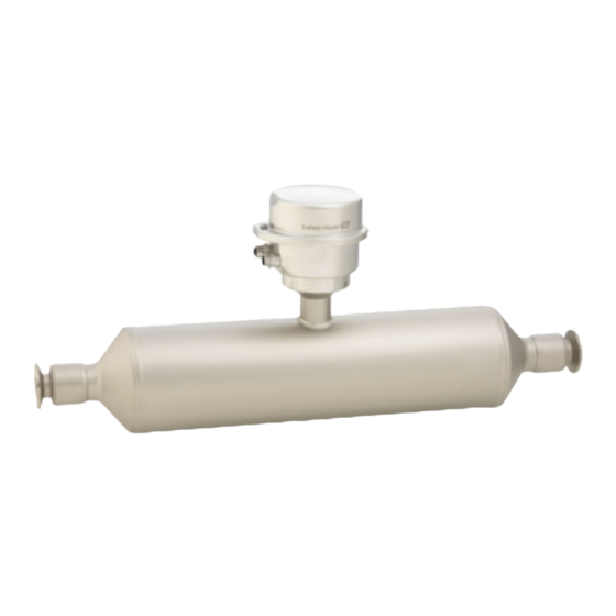
Endress+Hauser Proline Promass I 100 Operating Instructions Manual (120 pages)
Coriolis Flowmeter Modbus RS485
Brand:
Endress+Hauser
| Category:
Measuring Instruments
| Size: 3 MB
Table of Contents
Table of Contents
3
Endress+Hauser
5
About this Document
6
Document Function
6
Symbols
6
Safety Symbols
6
Electrical Symbols
6
Tool Symbols
6
Symbols for
7
Certain Types of Information
7
Symbols in Graphics
7
Documentation
7
Registered Trademarks
8
Safety Instructions
9
Requirements for the Personnel
9
Intended Use
9
Workplace Safety
10
Operational Safety
10
Product Safety
10
Security
10
Product Description
11
Product Design
11
Device Version with Modbus RS485 Communication Protocol
11
Incoming Acceptance and Product
12
Identification
12
Incoming Acceptance
12
Product Identification
12
Transmitter Nameplate
13
Sensor Nameplate
14
Promass 100 Safety Barrier Nameplate
15
Symbols on the Device
15
Storage and Transport
16
Storage Conditions
16
Transporting the Product
16
Measuring Devices Without Lifting Lugs
16
Measuring Devices with Lifting Lugs
17
Transporting with a Fork Lift
17
Packaging Disposal
17
Installation
18
Installation Requirements
18
Installation Position
18
Inlet and Outlet Runs
19
Environmental and Process Requirements
20
Thermal Insulation
20
Special Installation Instructions
21
Hygienic Compatibility
22
Installing the Measuring Instrument
23
Required Tools
23
Preparing the Measuring Instrument
23
Mounting the Measuring Device
24
Post-Installation Check
24
Electrical Connection
25
Electrical Safety
25
Connecting Requirements
25
Required Tools
25
Requirements for Connecting Cable
25
Terminal Assignment
26
Pin Assignment, Device Plug
29
Supply Voltage
29
Signal Transmission
29
Shielding and Grounding
30
Preparing the Measuring Device
30
Connecting the Measuring Instrument
30
Connecting the Transmitter
31
Connecting the Safety Barrier Promass 100
32
Potential Equalization
33
Requirements
33
Special Connection Instructions
33
Connection Examples
33
Hardware Settings
34
Activating the Terminating Resistor
34
Ensuring the Degree of Protection
35
Post-Connection Check
35
Operation Options
37
Overview of Operation Options
37
Structure and Function of the Operating Menu
38
Structure of the Operating Menu
38
Operating Philosophy
39
Displaying the Measured Values Via the Local Display (Optionally Available)
39
Operational Display
39
User Roles and Related Access Authorization
41
Access to the Operating Menu Via the Operating Tool
42
Connecting the Operating Tool
42
Fieldcare
42
User Interface
43
Devicecare
43
System Integration
44
Overview of Device Description Files
44
Current Version Data for the Device
44
Operating Tools
44
Modbus RS485 Information
44
Function Codes
44
Register Information
45
Response Time
45
Data Types
45
Byte Transmission Sequence
46
Modbus Data Map
47
Scan List Configuration
47
Commissioning
49
Post-Mounting and Post-Connection Check
49
Connecting Via Fieldcare
49
Setting the Operating Language
49
Configuring the Measuring Instrument
49
Defining the Tag Name
49
Parameter Overview with Brief Description
50
Setting the System Units
50
Selecting and Setting the Medium
53
Configuring the Communication Interface
54
Configuring the Low Flow Cut off
56
Configuring Partially Filled Pipe
57
Using the Parameter to Enter the Access Code
58
Advanced Settings
58
Calculated Process Variables
58
Carrying out a Sensor Adjustment
60
Density Adjustment
60
Configuring the Totalizer
64
Using Parameters for Device Administration
65
Simulation
65
Protecting Settings from Unauthorized Access
66
Write Protection Via Write Protection Switch
66
Operation
68
Reading the Device Locking Status
68
Adjusting the Operating Language
68
Reading off Measured Values
68
Measured Variables" Submenu
68
Totalizer" Submenu
71
Adapting the Measuring Device to the Process Conditions
72
Performing a Totalizer Reset
72
Function Scope of "Control Totalizer
73
Parameter
73
Function Range of "Reset All Totalizers" Parameter
74
Diagnostics and Troubleshooting
75
General Troubleshooting
75
Diagnostic Information Via Leds
75
Transmitter
75
Safety Barrier Promass 100
76
Diagnostic Information in Fieldcare or
77
Diagnostic Options
77
Calling up Remedy Information
78
Diagnostic Information Via Communication Interface
78
Reading out Diagnostic Information
78
Configuring Error Response Mode
78
Adapting the Diagnostic Information
79
Adapting the Diagnostic Behavior
79
Overview of Diagnostic Information
79
Pending Diagnostic Events
81
Diagnostics List
82
Event Logbook
82
Reading out the Event Logbook
82
Filtering the Event Logbook
83
Overview of Information Events
83
12.10 Resetting the Measuring Device
84
12.10.1 Function Range of "Device Reset" Parameter
84
12.11 Device Information
85
12.12 Firmware History
86
Maintenance
87
Maintenance Work
87
Exterior Cleaning
87
Internal Cleaning
87
Measuring and Test Equipment
87
Endress+Hauser Services
87
Repair
88
General Notes
88
Repair and Conversion Concept
88
Notes for Repair and Conversion
88
Spare Parts
88
Endress+Hauser Services
88
Return
88
Disposal
89
Removing the Measuring Device
89
Disposing of the Measuring Device
89
Accessories
90
Device-Specific Accessories
90
For the Sensor
90
Communication-Specific Accessories
90
Service-Specific Accessories
91
System Components
92
Technical Data
93
Application
93
Function and System Design
93
Input
94
Direct Measured Variables
94
Output
96
Light Emitting Diodes (LED)
96
Protocol-Specific Data
96
Power Supply
97
Performance Characteristics
99
Flow Values
100
Accuracy of Outputs
100
Influence of Medium Temperature
101
Mounting
103
Environment
103
Process
104
Flow Limit
105
16.10 Mechanical Construction
106
Transmitter Housing
107
16.11 Operability
109
16.12 Certificates and Approvals
109
Pharmaceutical Compatibility
110
16.13 Application Packages
112
Heartbeat Verification
112
Heartbeat Monitoring
112
16.14 Accessories
113
16.15 Supplementary Documentation
113
Technical Information
113
Special Documentation
114
Installation Instructions
114
Advertisement
Endress+Hauser Proline Promass I 100 Operating Instructions Manual (114 pages)
Modbus RS485 Coriolis flowmeter
Brand:
Endress+Hauser
| Category:
Measuring Instruments
| Size: 2 MB
Table of Contents
Table of Contents
3
1 Document Information
5
Document Function
5
Symbols Used
5
Safety Symbols
5
Electrical Symbols
5
Tool Symbols
6
Symbols for Certain Types of Information
6
Symbols in Graphics
6
Documentation
7
Standard Documentation
7
Supplementary Device-Dependent Documentation
7
Registered Trademarks
7
2 Basic Safety Instructions
8
Requirements for the Personnel
8
Designated Use
8
Workplace Safety
9
Operational Safety
9
Product Safety
9
3 Product Description
10
Product Design
10
Device Version with Modbus RS485 Communication Type
10
4 Incoming Acceptance and Product
11
Identification
11
Incoming Acceptance
11
Product Identification
12
Transmitter Nameplate
12
Sensor Nameplate
13
Promass 100 Safety Barrier - Nameplate
14
Symbols on Measuring Device
14
5 Storage and Transport
15
Storage Conditions
15
Transporting the Product
15
Packaging Disposal
16
6 Installation
17
Installation Conditions
17
Mounting Position
17
Requirements from Environment and Process
19
Special Mounting Instructions
20
Mounting the Measuring Device
22
Required Tools
22
Preparing the Measuring Device
22
Post-Installation Check
23
7 Electrical Connection
24
Connection Conditions
24
Required Tools
24
Requirements for Connecting Cable
24
Terminal Assignment
26
Pin Assignment, Device Plug
28
Shielding and Grounding
29
Preparing the Measuring Device
29
Connecting the Measuring Device
29
Connecting the Transmitter
30
Connecting the Safety Barrier Promass 100
31
Hardware Settings
32
Enabling the Terminating Resistor
32
Ensuring the Degree of Protection
32
Post-Connection Check
33
8 Operation Options
34
Overview of Operation Options
34
Structure and Function of the Operating Menu
35
Structure of the Operating Menu
35
Operating Philosophy
36
Access to the Operating Menu Via the Operating Tool
37
Connecting the Operating Tool
37
Fieldcare
37
9 System Integration
39
Overview of Device Description Files
39
Current Version Data for the Device
39
Operating Tools
39
Modbus RS485 Information
39
Function Codes
39
Register Information
40
Response Time
40
Modbus Data Map
40
10 Commissioning
43
Function Check
43
Establishing a Connection Via Fieldcare
43
Configuring the Measuring Device
43
Setting the System Units
43
Selecting and Setting the Medium
46
Interface
47
Configuring the Low Flow Cut off
49
Configuring the Partial Filled Pipe Detection
50
Advanced Settings
51
Defining the Tag Name
51
Calculated Values
51
Carrying out a Sensor Adjustment
52
Configuring the Totalizer
53
Simulation
54
Parameter Overview with Brief
54
Description
54
Protecting Settings from Unauthorized
55
Access
55
Write Protection Via Write Protection
55
Switch
55
11 Operation
57
Read Device Locking Status
57
Reading Measured Values
57
Process Variables
57
Totalizer
58
Adapting the Measuring Device to the Process
59
Conditions
59
Performing a Totalizer Reset
59
12 Diagnostics and Troubleshooting
61
General Troubleshooting
61
Diagnostic Information Via Light Emitting
61
Diodes
61
Transmitter
61
Safety Barrier Promass 100
62
Diagnostic Information in Fieldcare
62
Diagnostic Options
62
Calling up Remedy Information
63
Diagnostic Information Via Communication
63
Interface
63
Reading out Diagnostic Information
63
Configuring Error Response Mode
64
Adapting the Diagnostic Information
64
Adapting the Diagnostic Behavior
64
Overview of Diagnostic Information
65
Pending Diagnostic Events
67
Diagnostic List
67
Event Logbook
68
Event History
68
Filtering the Event Logbook
68
Overview of Information Events
68
12.10 Resetting the Measuring Device
69
12.11 Device Information
69
12.12 Firmware History
70
13 Maintenance
71
Maintenance Tasks
71
Exterior Cleaning
71
Interior Cleaning
71
Measuring and Test Equipment
71
Endress+Hauser Services
71
14 Repair
72
General Notes
72
Spare Parts
72
Endress+Hauser Services
72
Return
72
Disposal
72
Removing the Measuring Device
72
Disposing of the Measuring Device
73
15 Accessories
74
Device-Specific Accessories
74
For the Sensor
74
Communication-Specific Accessories
74
Service-Specific Accessories
75
System Components
75
16 Technical Data
76
Application
76
Function and System Design
76
Input
76
Output
78
Power Supply
80
Performance Characteristics
81
Installation
85
Environment
85
Process
86
16.10 Mechanical Construction
88
16.11 Operability
90
16.12 Certificates and Approvals
90
16.13 Application Packages
92
16.14 Accessories
93
16.15 Documentation
93
17 Appendix
94
Overview of the Operating Menu
94
Index
110
Endress+Hauser Proline Promass I 100 Technical Information (84 pages)
Coriolis
Brand:
Endress+Hauser
| Category:
Measuring Instruments
| Size: 2 MB
Table of Contents
Table of Contents
2
Document Information
4
Symbols Used
4
Function and System Design
5
Measuring Principle
5
Measuring System
6
Device Architecture
7
Safety
7
Input
7
Measured Variable
7
Measuring Range
8
Operable Flow Range
9
Output
9
Output Signal
9
Signal on Alarm
10
Low Flow Cut off
10
Galvanic Isolation
13
Protocol-Specific Data
13
Power Supply
19
Terminal Assignment
19
Pin Assignment, Device Plug
25
Supply Voltage
25
Power Consumption
27
Current Consumption
28
Power Supply Failure
28
Electrical Connection
28
Potential Equalization
32
Terminals
32
Cable Entries
33
Cable Specification
33
Performance Characteristics
34
Reference Operating Conditions
34
Maximum Measured Error
34
Repeatability
36
Response Time
36
Influence of Ambient Temperature
36
Influence of Medium Temperature
36
Influence of Medium Pressure
37
Design Fundamentals
37
Installation
38
Mounting Location
38
Orientation
40
Inlet and Outlet Runs
40
Mounting Safety Barrier Promass 100
42
Environment
42
Ambient Temperature Range
44
Storage Temperature
44
Climate Class
44
Degree of Protection
44
Shock Resistance
44
Vibration Resistance
44
Interior Cleaning
44
Electromagnetic Compatibility (EMC)
45
Process
45
Medium Temperature Range
45
Density
45
Pressure-Temperature Ratings
45
Secondary Containment Pressure Rating
48
Flow Limit
48
Pressure Loss
49
System Pressure
49
Thermal Insulation
49
Heating
50
Vibrations
51
Mechanical Construction
52
Design, Dimensions
52
Weight
71
Materials
72
Process Connections
74
Operability
74
Operating Concept
74
Local Display
74
Remote Operation
74
Service Interface
76
Certificates and Approvals
78
CE Mark
78
C-Tick Symbol
78
Ex Approval
78
Hygienic Compatibility
79
Certification PROFIBUS
79
Modbus RS485 Certification
79
Ethernet/Ip Certification
79
Pressure Equipment Directive
79
Other Standards and Guidelines
79
Ordering Information
80
Application Packages
80
Concentration
81
Viscosity
81
Accessories
81
Device-Specific Accessories
81
Communication-Specific Accessories
81
Service-Specific Accessories
82
System Components
83
Documentation
83
Standard Documentation
83
Supplementary Device-Dependent Documentation
83
Advertisement
Advertisement
Related Products
Endress+Hauser ATEX II2GD
Endress+Hauser ATEX II1/2GD
Endress+Hauser HART Proline t-mass I 300
Endress+Hauser II21GD
Endress+Hauser Prosonic Flow I 400
Endress+Hauser IO-Link Dosimag
Endress+Hauser Proline Promass 83
Endress+Hauser Proline Promass 80H
Endress+Hauser Proline Promass 83H
Endress+Hauser Proline Promass 80E
Endress+Hauser Categories
Measuring Instruments
Transmitter
Radar
Switch
Accessories
More Endress+Hauser Manuals
Login
Sign In
OR
Sign in with Facebook
Sign in with Google
Upload manual
Upload from disk
Upload from URL