Sign In
Upload
Manuals
Brands
Emerson Manuals
Controller
Vilter MicroVission
Emerson Vilter MicroVission Manuals
Manuals and User Guides for Emerson Vilter MicroVission. We have
2
Emerson Vilter MicroVission manuals available for free PDF download: Operation And Service Manual, Retrofit Manual
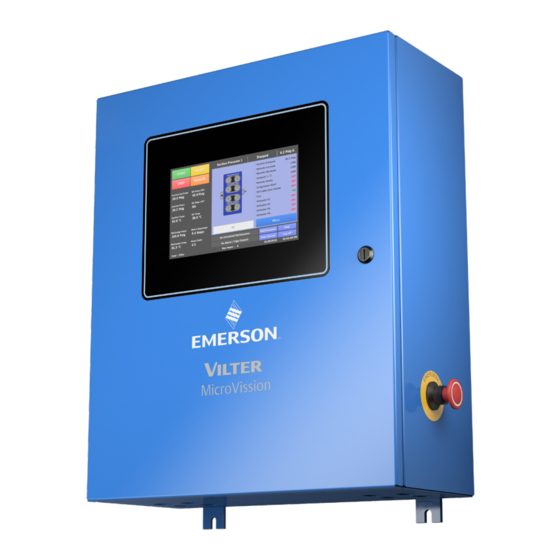
Emerson Vilter MicroVission Operation And Service Manual (262 pages)
Brand:
Emerson
| Category:
Controller
| Size: 32 MB
Table of Contents
Standard VILTER™ Warranty Statement
3
Important Message
5
Table of Contents
7
How to Use this Manual
19
Section 1 • Installation Recommendations
21
Proper Wiring Sizing
21
Voltage Source
21
Figure 1-1. Microvission with Individual Transformer
21
Figure 1-2. EMI and Microvission
21
Grounding
22
Mixing Voltages
22
DC Signals
22
Figure 1-4. Mixed Voltage Wiring
22
Wiring Methods
23
Figure 1-5. Correct Transformer Wiring Method
23
Figure 1-6. Incorrect Transformer Wiring Method
23
Best Practices
24
Transformers, Fusing and UPS Sizing
24
Section 2 • Hardware Architecture Overview
25
Multi-I/O (Input/Output) Board
25
Figure 2-1. Hardware Architecture Overview
25
Multi-IO Board Digital I/O
26
Figure 2-2. Multi I/O Board Layout
26
Table 2-1. Multi-IO Board (Digital I/O)
27
Multi-IO Board Analog I/O
28
Table 2-2. Multi-IO Board (Analog I/O)
28
Multi-IO Board Analog Input Jumper Tables
29
Digital In-Out Board
30
Figure 2-3. Digital Input-Output Board Layout
30
Digital In-Out Board I/O
31
Table 2-4. Auxiliary Digital I/O)
31
Analog Input Board
32
Figure 2-4. Analog Input Board Layout
32
Analog Input Board I/O
33
Table 2-5. Auxiliary Analog Input
33
Analog Input Board Jumper Tables
34
Advisory for First Generation Microvission Panels
36
Figure 2-5. Jumper J4 on the Processor Board
36
Section 3 • Main Screen Overview
37
Figure 3-1. Main Screen
37
Top Status Bar
38
Figure 3-2. Top Status Bar
38
Parameters Bar
39
Figure 3-3. Parameters Bar
39
Control Parameters Box
40
Figure 3-4. Start Dialog Box
40
Bottom Status Bar
41
Figure 3-5. Bottom Status Bar
41
Splash Screen
42
Figure 3-6. Warning Pop-Up Window
42
Figure 3-7. Splash Screen
42
Figure 3-8. Manual Run Mode Buttons and Progress Bar
42
Progress Bar
43
Status Icons on Main Screen
43
Figure 3-9. Pumpdown Operation Running Icon
43
Figure 3-10. Pulldown Operation Running Icon
44
Figure 3-11. Compressor Sequencing Icon
44
Figure 3-12. Condenser Control Operation Running Icon
45
Section 4 • Menu Screen Overview
47
Navigation Buttons
47
Figure 4-1. Menu Screen
47
Section 5 • Compressor Control Overview
49
How Compressor Control Setpoint Works
49
Suction Pressure Control
50
Figure 5-1. Compressor Control Screen - Suction Pressure Control
50
Process Temperature Control
51
Figure 5-2. Compressor Control Screen - Process Temperature Control
51
Discharge Pressure Control
52
Figure 5-3. Compressor Control Screen - Discharge Pressure Control
52
Auto Cycle
53
Active Control Mode
58
Load Limiting
58
Oil Control
60
Compressor Variable Frequency Drive(VFD) Control
61
Pumpdown Control
62
Pulldown Control
64
Section 6 • Alarms and Trips Screen
67
Overview
67
Warnings
67
Inhibits
67
Alarms
67
Trips
67
Freeze Screens
67
Logging - Event List
67
Alarms & Trips Setpoints
68
Microvission Safety Messages
70
Low Suction Pressure
70
High Discharge Pressure
70
Low Process Temperature
70
High Process Temperature
71
Low Suction Temperature
71
High Discharge Temperature
71
Low Crankcase Oil Temperature - Start
72
Low Crankcase Oil Temperature - Run
72
High Crankcase Oil Temperature
72
Low Oil Pressure Diff
73
High Filter Diff Pressure Start
73
High Filter Diff. Pressure - Run
74
High Motor Amps
74
High Discharge #2 Pressure
74
High Discharge #2 Temperature
75
Remote Comm Time out
75
Compressor Interlock
75
High Level Shutdown
76
Starter
76
False Start
76
IO Comm
77
Low Oil Level
77
Low Discharge Pressure
77
Low Discharge Temperature
77
Low Oil Filter in Pressure
78
Low Oil Filter out Pressure
78
Low Discharge 2 Pressure
78
Low Discharge #2 Temperature
78
Auxiliary Safety Messages
79
Digital aux in 1
80
Digital aux in 2
80
Digital aux in 3
81
Digital aux in 4
81
Analog aux in 1
82
Analog aux in 2
83
Analog aux in 3
83
Analog aux in 4
84
Analog aux in 5
84
Analog aux in 6
84
Analog aux in 7
84
Analog aux in 8
86
Result Variable Safety Messages
87
Digital Result Variable
87
Analog Result Variable
88
Section 7 • Timers Overview
89
Timer Setpoints
89
Section 8 • Instruments Calibration Overview
93
I/O
93
Pressure & Temperature Inputs
93
Device Calibration
93
Channel Calibration
93
Analog Inputs - Pressure
94
Analog Inputs
98
Motor Current
98
4-20Ma Scale
98
Process Temperature or Pressure
99
Auxiliary Inputs
100
Device Calibration
100
Channel Calibration
100
Analog Outputs
102
Section 9 • Event List Overview
105
Event List Columns
105
Section 10 • Input / Output States Screen Overview
107
Section 11 • User Access Overview
113
Login
114
Manage Accounts
114
Screen Security Levels
115
Table 11-1. Security Access Levels
115
Section 12 • Configuration Screen Overview
117
Units
117
Compressor Control
118
Oil Monitoring
118
Oil Level Trip
118
Touch Screen
118
Table 12-1. 12/16 Cylinder Configuration Setup
118
Anti Recycle
119
Compressor VFD
119
Restart on Power Failure
119
Compressor Identification
120
Date and Time
120
Language
121
Alarms and Trips
121
Communication
121
Active Remote Control
121
Table 12-2. Condenser Control Setup
121
Direct I/O
122
Run Permissive
122
On Communication Failure
122
Ethernet
122
Table 12-3. Direct I/O Setup
122
Serial (Modbus RTU)
123
VNC Account
123
Compressor Sequencing
124
Configurable Main Screen Settings
124
Digital Inputs
126
Analog Inputs
126
Digital Outputs
126
Analog Outputs
126
Virtual Digital Inputs
128
Virtual Analog Inputs
128
I/O Configuration
129
Section 13 • Data Backup Overview
131
Refresh
131
Save/Load
131
Available Devices
132
Factory Reset
133
Setpoints Report
133
Database Backup Procedure
134
Section 14 • Maintenance Screen Overview
137
Chart Tab
137
Notes Tab
142
Log Tab
143
Section 15 • Compressor Scheduling Overview
145
Scheduling Setpoint
145
Section 16 • Service Options Overview
147
Digital Outputs
147
Analog Outputs
149
Section 17 • Trend Chart Overview
151
Chart Operation
151
Trend Data Storage
152
Trend Setup
153
Section 18 • Help Screen Overview
155
Screen Features
155
Section 19 • Compressor Sequencing Overview
159
Compressor Sequencing Table
159
Status Symbols
160
Table 19-1. Status Symbols
160
Suction Pressure Control Setpoint
161
Process Temp. Control Setpoint
161
Sequencing Control Mode
163
Devices List
163
View Detected Devices
164
Delete Device
165
Test Connection
167
Compressor Sequencing Events Log
168
Configuration Overview
169
Setting up the Other Compressors for Sequencing
169
Section 20 • Auxiliary I/O Overview
173
Digital Inputs
173
Digital Outputs
174
Analog Inputs
177
Analog Outputs
178
Auxiliary IO Result Variables
181
Section 21 • Condenser Control Overview
185
Condenser Control Set Points
186
Step Control
188
Section 22 • Parts
189
How to Read a Parts List and Illustration
189
Vilter Aftermarket Parts Contact Information
189
Microvission - Main Enclosure Electrical Components
191
Microvission - SBC Assembly
193
Section 23 • Warranty Claim Processing
195
Warranty Claim Processing
195
Appendix C • Remote Control and Monitoring
231
Introduction
231
Networking
231
Communication Wire
231
Ethernet Cable Specifications
231
RS-482/485 Cable Specifications
231
Common Register Setup to Control the Microvission (Compressor Control) Via Communications
232
Compressor Start and Stop Commands
235
Remote Control Via Direct I/O (Hard-Wired
236
Control Scenario
239
Communication Port Setup
239
Appendix D • Compressor Sequencing Setup
241
Microvission Compressor Sequencing Setup
241
Scope
241
Overview
241
Configuration Overview
241
Compressor Sequencing Equipment List
244
Configuring Sequencing Table on Compressor
246
Walk-Through of Sequencing Loading and Unloading
246
Overview of Compressor Unloading
248
Compressor Experiencing a Failure
249
Microvission Compressor Sequencing Setup and Configuration Overview
250
Configuration Overview
251
Setting up the Microvission Compressor Sequencing Parameters
252
Adding Microvission Panels to the Devices List
252
Testing the Microvission Panel Connections
254
Deleting Microvission Panels from the Devices List
255
Setting up the Compressor Sequencing Table
256
Final Steps for Setting up Compressor Sequencing
257
Appendix E • Abbreviations Used on the Microvission Panel Screen
259
Abbreviations Used on the Microvission Panel Screen
259
Advertisement
Emerson Vilter MicroVission Retrofit Manual (20 pages)
Brand:
Emerson
| Category:
Controller
| Size: 1 MB
Table of Contents
Table of Contents
2
Table of Contents 1.0 General Information
2
1 0 General Information
3
2 Microvission Installation Recommendations
3
Installation When Retrofitting from Viltech, Vantage, or Keypad Control Panels
3
Figure 2. Keypad UL Retrofit
4
Figure 3. Microvission Panel on Support Bracket
5
Figure 5. Tri-Micro Filter with Pressure Transducers
6
Installation When Retrofitting from Pressure Switches
7
Drive (Right)
8
Mounting (Right)
8
Figure 9. Tubing According to Compressor´s Drive: Direct Drive (Left) & Belt Drive (Right)
8
Figure 11. Well & Transducers Location
9
Pressures
10
Figure 14. Connection of 4-20Ma Current Transmitter (Sensor)
11
3 Field Wiring
12
Power and Input/Output Wiring at the Panel
12
Figure 16. Digital Input/Output Wiring
13
Figure 17. Analog Input Wiring
14
Order of Analog Inputs
15
5 Power-Up Microvission and Enter Setpoints
15
6 Pressure Testing and Returning Compressor to Service
15
Advertisement
Related Products
Emerson Vilter Vission 20/20
Emerson VSG 901
Emerson VSG 2601
Emerson VSG2801
Emerson VSX8L
Emerson VSX8 Series
Emerson VSX4H
Emerson VSX4L
Emerson VSX8H
Emerson Vilter VilTech
Emerson Categories
Controller
Control Unit
Transmitter
Measuring Instruments
Fan
More Emerson Manuals
Login
Sign In
OR
Sign in with Facebook
Sign in with Google
Upload manual
Upload from disk
Upload from URL