Sign In
Upload
Manuals
Brands
Emerson Manuals
Air Conditioner
Liebert XDP
Emerson Liebert XDP Manuals
Manuals and User Guides for Emerson Liebert XDP. We have
1
Emerson Liebert XDP manual available for free PDF download: User Manual
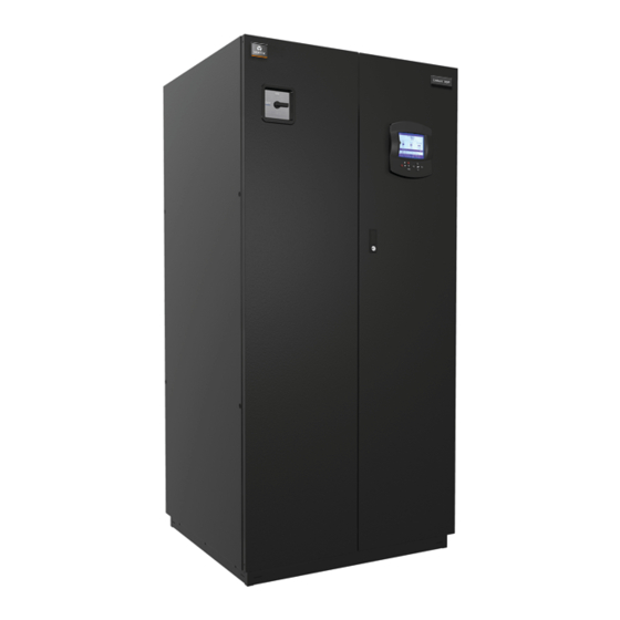
Emerson Liebert XDP User Manual (80 pages)
Refrigerant distribution unit with Liebert Icom control
Brand:
Emerson
| Category:
Air Conditioner
| Size: 2.9 MB
Table of Contents
Table of Contents
3
Important Safety Instructions
7
Figure 1 Model Number Nomenclature
8
1 Product Description
9
General Product Information
9
Product/System Description
9
Minimum Load
9
Equipment Inspection
9
Figure 2 Liebert XDP Components
9
Equipment Handling
10
Handling the Liebert XDP While It Is on Skid and Packaged
10
Unpacking the Liebert XDP
11
Removing the Unit from the Skid Using a Forklift
11
Figure 3 Unpacking the Liebert XDP
11
Removing the Unit from the Skid Using Rigging
12
Figure 4 Use a Forklift to Remove the Liebert XDP from the Skid
12
Moving the Liebert XDP Using Piano Jacks
13
Figure 5 Removing the Unit from the Skid Using Rigging
13
Removing the Unit from the Piano Jacks
14
Figure 6 Securing the Liebert XDP to Piano Jacks
14
2 Installation
15
Mechanical Considerations
15
Positioning the Liebert XDP
15
Figure 7 Dimensions
15
Table 2 Liebert XDP Dimensions
15
Electrical Considerations
16
Figure 8 Piping Access Points
16
Table 3 Unit Piping Outlet Connection Sizes, Inches, OD Cu
16
Connecting High-Voltage Cables
17
Figure 9 Front View of Liebert XDP and Electrical Enclosure
17
Figure 10 Electrical Enclosure Knockout Location for Hazardous Voltage Wiring
18
Figure 11 High Voltage Connections-60Hz
18
Extra Low Voltage (ELV) Connections
19
Figure 12 High Voltage Connections-50Hz
19
Figure 13 Electrical Enclosure Knockout Locations for Extra Low Voltage
19
Figure 14 Connecting the Remote Temperature/Humidity Sensors
20
DIP Switch and Jumper Settings for Remote Sensors
21
Figure 15 DIP Switch and Jumper Settings
21
Figure 16 Unit-To-Unit Networking Connections
21
Field Connections-Optional for All Units
22
Figure 17 Liebert XDP Extra Low Voltage Field Connections Points
22
Remote Sensor Installation-Proper Placement
23
Figure 18 Suggested Remote Sensor Placement
23
3 Piping
24
European Union Fluorinated Greenhouse Gas Requirements
24
Connection Sizes
24
Recommended Pipe Size
24
Table 4 Supply, Return Pipe Sizes for Refrigerant Loop
24
Liebert XDP Interconnection with Liebert XD Cooling Modules
25
Piping Installation Methods
25
Piping Installation-R-134A Pumped Circuit
25
Figure 19 Liebert XD System Diagram
25
Piping Mains
26
Bypass Flow Controller
26
Figure 20 Bypass Flow Controller Details, Dimensions
26
Table 5 Bypass Flow Controllers for a Liebert XDP-Based System
26
Piping Details-Shutoff/Isolation Valves
27
Figure 21 Bypass Flow Controller Arrangement
27
Figure 22 Bypass Flow Controller Piping
27
Evacuation and Leak Check-R-134A Pumped Circuit
28
Figure 23 General Piping Details
28
Insulation
28
Filling the Pumped Circuit-R-134A
29
Table 6 System R-134A Charge for a Liebert XDP with any Model Liebert Xdh/Liebert XDO
29
Table 7 System Refrigerant Charge for the Supply and Return Mains
29
Table 8 R-134A Refrigerant Charge for Hard-Piped Connector Lines to and from any Model Liebert Xdh/Liebert Xdo/Liebert XDV/Liebert Xdcf/Liebert XDR
29
Calculating Refrigerant Charge-Example
30
Table 10 Calculating Refrigerant Charge-Example
30
Table 11 Worksheet to Calculate Refrigerant Charge
30
Table 9 R-134A Refrigerant Charge for Flex Pipe Connector Lines to and from any Model Liebert Xdo/Liebert Xdh/Liebert XDV/Liebert Xdcf/Liebert XDR
30
Checklist for Proper Installation
31
4 Liebert Icom Control-Firmware Version XP1.00.010.STD
32
Liebert Icom Components and Functions
32
Figure 24 Liebert Icom Display Components
32
Display Lamp Indicators
33
Table 12 Keyboard Icons and Functions
33
Navigating through the Liebert Icom Display
34
Accessing Menus and Settings
34
Figure 25 Liebert Icom Default Home Screen
34
Cooling Module Overview
35
Figure 26 Cooling Module Overview, First 10 Modules
35
Entering the Password
36
Figure 27 Entering the Password
36
Changing Liebert Icom's Display Settings
37
Changing Operational Settings
37
Figure 28 Display Setup Screen
37
Graphical Data Record
38
Liebert Icom User Menu Icons and Legend
38
Figure 29 Liebert Icom User Menu Icons
38
Figure 30 Liebert XDP User Menu Screen
39
Liebert Icom User Menu Screens
40
Figure 31 Setpoints Screen
40
Figure 32 Set Alarms Screen
41
Figure 33 Sensor Data Screen, Page 1 of 2
42
Figure 34 Sensor Data Screen, Page 2 of 2
43
Figure 35 Display Setup Screen
44
Figure 36 Module Status Screen, Page 1 of 20
45
Figure 37 Liebert XDV Smart Module Status Screen
45
Figure 38 Liebert XDH Smart Module Status Screen-Each Bank Shown Separately
46
Figure 39 Liebert XDO Smart Module Status Screen
46
Liebert Icom Service Menu Icons and Legend
47
Figure 40 Total Run Hours Screen
47
Figure 41 Liebert Icom Service Menu Icons
47
Liebert Icom Service Menu Screens
48
Figure 42 Liebert XDP Service Menu Screen
48
Figure 43 Setpoints Screen
48
Figure 44 Maintenance-Basic Settings Screen, Page 1 of 7
50
Figure 45 Maintenance-Pump 1 Settings Screen, Page 2 of 7
51
Figure 46 Maintenance-Pump 2 Settings Screen, Page 3 of 7
52
Figure 47 Maintenance Screens, Pages 4 through 7
52
Figure 48 Diagnostics/Service Mode Screen, Page 1 of 6
53
Figure 49 Diagnostics/Service Mode Screen, Page 2 of 6
53
Figure 50 Diagnostics/Service Mode Screen, Page 3 of 6
54
Figure 51 Diagnostics/Service Mode Screen, Page 4 of 6
54
Figure 52 Diagnostics/Service Mode Screen, Page 5 of 6
55
Figure 53 Diagnostics/Service Mode Screen, Page 6 of 6
55
Figure 54 Set Alarms Screen, Page 1 of 7
56
Figure 55 Set Alarms Screen, Page 2 of 7
57
Figure 56 Set Alarms Screen, Page 3 of 7
58
Figure 57 Set Alarms Screen, Page 4 of 7
59
Figure 58 Set Alarms Screens, Pages 5 and 6
60
Figure 59 Set Alarms Screen
60
Figure 60 Sensor Calibration/Setup Screen, Page 1 of 3
61
Figure 61 Sensor Calibration/Setup Screen, Page 2 of 3
62
Figure 62 Sensor Calibration/Setup Screen, Page 3 of 3
62
Figure 63 System/Network Setup Screen-System, Page 1 of 2
63
Figure 64 System/Network Setup Screen-System, Page 2 of 2
64
Figure 65 System/Network Setup Screen-Unit, Page 1 of 2
65
Figure 66 System/Network Setup Screen-Unit, Page 2 of 2
66
Figure 67 Options Setup Screen, Page 1 of 2
67
Figure 68 Options Setup Screen, Page 2 of 2
68
Figure 69 Module Setup Screen, Page 1 of 20
68
Figure 70 Module Setup Screen, Page 1 of 20
69
5 Start the Liebert Lxdp with Liebert Icom
70
Checklist for Liebert XDP Startup
70
Table 13 Liebert XDP Pump Light Indicator-208V and 400V Units
70
Starting the Liebert XDP with Liebert Icom Controller
71
Figure 71 System R-134A Liquid Level at 160Kw Load
71
6 Alarm Descriptions and Solutions
72
Alarm Descriptions
72
Warning Descriptions
74
System Shutdown Causes
74
7 Troubleshooting
75
Table 14 Table
75
Table 14 Troubleshooting the Liebert XDP
75
8 Maintenance
77
Fluorinated Greenhouse Gas Requirements
77
9 Specifications
78
Table 15 Liebert XDP160 Specifications
78
Compliance with European Union Directives
79
Advertisement
Advertisement
Related Products
Emerson Liebert Prop Fan Condensing Unit
Emerson Liebert PEX Series
Emerson Liebert SRC Series
Emerson Liebert.CRV+ Series
Emerson Liebert PEX
Emerson LSF24
Emerson LSF52
Emerson LSF85
Emerson LDF52
Emerson LDF62
Emerson Categories
Controller
Control Unit
Transmitter
Measuring Instruments
Fan
More Emerson Manuals
Login
Sign In
OR
Sign in with Facebook
Sign in with Google
Upload manual
Upload from disk
Upload from URL