Sign In
Upload
Manuals
Brands
Emerson Manuals
Air Conditioner
Liebert CW026
Emerson Liebert CW026 Manuals
Manuals and User Guides for Emerson Liebert CW026. We have
2
Emerson Liebert CW026 manuals available for free PDF download: Design Manual
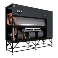
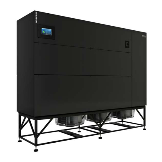
Emerson Liebert CW026 Design Manual (132 pages)
Liebert CW Thermal Management System
Brand:
Emerson
| Category:
Air Conditioner
| Size: 6.81 MB
Table of Contents
3
Table of Contents
11
Nomenclature and Components
11
Liebert CW Nomenclature
13
Components
13
Figure 1-1 Downflow Model Component Locations
14
Figure 1-2 Upflow Model Component Locations
15
Blower Configurations
15
Figure 1-3 Blower Configurations-Downflow, Front and Rear Supply, EC Fans
15
Figure 1-4 Blower Configurations-Downflow, Bottom and Under-Floor Supply, EC Fans
16
Figure 1-5 Blower Configurations-Downflow, Under-Floor Supply, Forward-Curved Blowers
16
Figure 1-6 Blower Configurations-Upflow, EC Fans in Plenum
17
Figure 1-7 Blower Configurations-Upflow, Front Return, Forward-Curved Blowers
17
Figure 1-8 Blower Configurations-Upflow, Rear Return, Forward-Curved Blowers
19
Liebert CW System Data
19
Table 2-1 Performance Data, CW026-CW400, 50/60Hz, Upflow and Downflow Models with EC Fans
20
Table 2-2 Performance Data, CW026-CW114, 50/60Hz, Upflow and Downflow Models with Forward-Curved Blowers
21
Table 2-3 Performance Data for Select Liebert CW Units with EC Fans, High Delta T Conditions
22
Table 2-4 Motor Size Required to Deliver Rated Airflow, Models with Forward-Curved Blowers
22
Table 2-5: Maximum Airflow
23
Table 2-6 Physical Data, Liebert CW026 - CW089, 50/60Hz Models
25
Table 2-7 Physical Data-Liebert CW106 - CW400, 50/60Hz Models
27
Electrical Data
27
Table 3-1 Electrical Data, Liebert CW with EC Fans, 60Hz
28
Table 3-2 Electrical Data-Forward-Curved Blowers, 60Hz Systems
30
Table 3-3 Indoor Evaporator Fan Motor Electrical Requirements-60Hz Systems
31
Table 3-4 Electrical Data-Ec Fan Models, 50Hz
32
Table 3-5: Electrical Data-Forward-Curved Blowers, 50Hz Systems
32
Table 3-6: Indoor Evaporator Fan Motor Electrical Requirements
33
Dimensions
33
Location Considerations
34
Cabinet and Floor-Planning Dimensions-Downflow Models with EC Fans
34
Figure 4-1 Cabinet and Floor-Planning Dimensions, Downflow, CW026 - CW084 with EC Fans
35
Figure 4-2 Cabinet and Floor-Planning Dimensions, Downflow, CW026, CW038 and CW041, with EC Fans, Front Discharge
36
Figure 4-3 Cabinet and Floor-Planning Dimensions, Downflow, CW051, CW060, CW076 and CW084, with EC Fans, Front Discharge
37
CW089, CW106 and CW114 with EC Fans
38
Figure 4-5 Cabinet and Floor-Planning Dimensions, Downflow, CW089, CW106 and CW114 with EC Fans, Front Discharge
39
Figure 4-6 Cabinet and Floor-Planning Dimensions, Downflow, CW146 and CW181 with EC Fans
40
Figure 4-7: Cabinet and Floor-Planning Dimensions, Downflow CW146 and CW181, with EC Fans, Front Discharge
41
Figure 4-8 Cabinet and Floor-Planning Dimensions, Downflow, CW300, CW400 with EC Fans and Filter Plenums
42
Cabinet and Floor-Planning Dimensions-Upflow Models with EC Fans
42
Figure 4-9 Cabinet and Floor-Planning Dimensions, Upflow, CW026 - CW084 with EC Fans, Front Air Return
43
Figure 4-10 Cabinet and Floor-Planning Dimensions, Upflow, CW026 - CW084 with EC Fans, Rear and Bottom Air Return
44
Figure 4-11 Cabinet and Floor-Planning Dimensions, Upflow, CW106, CW114 with EC Fans, Front Return
45
Figure 4-12 Cabinet and Floor-Planning Dimensions, Upflow, CW106, CW114 with EC Fans, Rear Return
46
Cabinet and Floor-Planning Dimensions -Downflow Models with Forward-Curved Blowers
46
Figure 4-13 Cabinet and Floor-Planning Dimensions, Downflow, CW026 - CW084, with Forward-Curved Blowers
47
Figure 4-14 Cabinet and Floor-Planning Dimensions, Downflow, CW106 and CW114 with Forward-Curved Blowers
48
Cabinet and Floor-Planning Dimensions-Upflow Models with Forward-Curved Blowers
48
Figure 4-15 Cabinet and Floor-Planning Dimensions, Upflow, CW026 - CW084 with Forward-Curved Blowers
49
Figure 4-16 Cabinet and Floor-Planning Dimensions, Upflow, CW106 and CW114 with Forward-Curved Blowers
50
Floor-Stand Dimensions-Units with EC Fans
50
Figure 4-17 Floor-Stand and Floor-Planning Dimensions, Downflow, CW026 - CW041 with EC Fans
51
Figure 4-18 Floor-Stand and Floor-Planning Dimensions, Downflow, CW051 and CW060 with EC Fans
52
Figure 4-19 Floor-Stand and Floor-Planning Dimensions, Downflow, CW076 and CW084 with EC Fans
53
Figure 4-20 Floor-Stand and Floor-Planning Dimensions, Downflow, CW089, CW106 and CW114 with EC Fans
54
Figure 4-21 Floor-Stand and Floor-Planning Dimensions, Downflow, CW089, CW106 and CW114 with EC Fans
55
Figure 4-22 Floor-Stand and Floor-Planning Dimensions, Downflow, CW300 and CW400 with EC Fans
56
Floor-Stand Dimensions-Units with Forward-Curved Blowers
56
Figure 4-23 Floor-Stand Planning Dimensions, CW026 - CW084 with Forward-Curved Blowers
57
Figure 4-24 Floor-Stand Planning Dimensions, CW106 and CW114 with Forward-Curved Blowers
58
Plenum Dimensions-Units with EC Fans
58
Figure 4-25 Plenum Dimensions, Upflow, CW026 - CW084 with EC Fans
59
Figure 4-26 Plenum Dimensions, Upflow, CW106, CW114 with EC Fans
60
Plenum Dimensions-Units with Forward-Curved Blowers
60
Figure 4-27 Plenum Dimensions, Upflow, CW026 - CW084 with Forward-Curved Blowers
61
Figure 4-28 Plenum Dimensions, Upflow. CW106 and CW114 with Forward-Curved Blowers
63
Piping
63
Piping General Arrangement
63
Figure 5-1 Piping General Arrangement, Downflow, CW026 - CW114
64
Figure 5-2 Piping General Arrangement, Downflow, CW146 - CW181
65
Figure 5-3 Piping General Arrangement, Upflow, CW026 - CW114
66
Piping Connections-Downflow Models with EC Fans
66
Figure 5-4 Primary Connection Locations, Downflow, CW026 - CW041 with EC Fans
67
Figure 5-5 Primary Connection Locations, Downflow, CW051 and CW060 with EC Fans
68
Figure 5-6 Primary Connection Locations, Downflow, CW076 - CW084 with EC Fans
69
Figure 5-7 Primary Connection Locations, Downflow, CW089, CW106 and CW114 with EC Fans
70
Figure 5-8 Primary Connection Locations, Downflow, CW146 and CW181 with EC Fans
71
Figure 5-9 Primary Connection Locations, Downflow, CW300 and CW400 with EC Fans
72
Piping Connections-Downflow Models with Forward-Curved Blowers
72
Figure 5-10 Piping Connections, Downflow, CW026 - CW084 with Forward-Curved Blowers
73
Figure 5-11 Piping Connections, Downflow, CW106 and CW114 with Forward-Curved Blowers
74
Piping Connections-Upflow Models
74
Figure 5-12 Piping Connections, Upflow, CW026 - CW084
75
Figure 5-13 Piping Connections, Upflow, CW106 and CW114
77
Electrical Field Connections
77
Electrical Field Connections-Downflow Models
77
Figure 6-1 Electrical Field Connections, Downflow, CW026 - CW084
78
Figure 6-2 Electrical Field Connections (Ethernet), Downflow, CW026 - CW084
79
Figure 6-3 Electrical Field Connections, Downflow, CW089, CW106 and CW114
80
Figure 6-4 Electrical Field Connections (Ethernet), Downflow, CW089, CW106 and CW114
81
Figure 6-5 Electrical Field Connections, Downflow, CW146 and CW181 with EC Fans
81
Standard Electrical Connections for Downflow Models CW146 and CW181
82
Optional Electrical Connections for Downflow Models CW146 and CW181
82
Optional Low-Voltage Terminal Package Connections
83
For Downflow Models CW146 and CW181
84
Electrical Field Connections-Upflow Models
84
Figure 6-6 Electrical Field Connections (High Voltage), Upflow, CW026 - CW084
85
Figure 6-7 Electrical Field Connections (Low Voltage), Upflow, CW026 - CW084
86
Figure 6-8 Electrical Field Connections (Ethernet), Upflow, CW026 - CW084
87
Figure 6-9 Electrical Field Connections (High-Voltage), Upflow, CW089 - CW114
88
Figure 6-10 Electrical Field Connections (Low-Voltage), Upflow, CW089 - CW114
89
Figure 6-11 Electrical Field Connections (Low Voltage Ethernet), Upflow, CW089 - CW114
91
Appendix A: Optional Configuration for Liebert CW Seismic Application
91
Seismic Certification Criteria
91
Site Requirements
91
Table A-1 Comparison of Certification Criteria, 2000-2006
92
Requirements for Seismic Anchorage
92
Anchor and Load Requirements of Seismic Installation
92
Table A-2 Downflow Liebert CW Models On Floor Stand with 36" Plenum, CW026-CW081
93
Table A-3 Upflow Liebert CW Models On Floor Stand with 36" Plenum, CW026-CW114
93
Table A-4 Downflow Liebert CW Models On Floor Stand Without Plenum, CW026-CW081
93
Table A-5 Upflow Liebert CW Models On Floor Stand Without Plenum, CW026-CW114
94
Table A-6 Upflow Liebert CW Models Direct Mount to Concrete Without Plenum, CW026-CW114
94
Table A-7 Upflow Liebert CW Models Direct Mount to Concrete with 36" Plenum, CW026-CW114
95
Figure A-1 Field-Welding of Anchor Bracket-Seismic Anchorage Rigid Floor Stand, Upflow, CW026 - CW114
96
Figure A-2 Anchor Detail-Seismic Anchorage Rigid Floor Stand, Downflow, CW026 - CW181
97
Figure A-3 Seismic Certification As Tested Connection Detail, Upflow, CW114 and CW181
98
Figure A-4 Ibc-Certified Seismic Floor Stand Data, Downflow, CW026 - CW114 with EC Fans
99
Figure A-5 Ibc-Certified Seismic Floor Stand Data, Downflow, CW146 - CW181 with EC Fans
100
Figure A-6 Upflow Plenum Seismic Mounting Data, CW026 - CW114
101
Figure A-7 Downflow Plenum Seismic Mounting Data, CW026 - CW114
102
Figure A-8 Seismic Duct Connection Considerations
103
Figure A-9 Seismic Electrical Wiring Considerations
104
Figure A-10 Seismic Piping Considerations
105
Appendix B: Optional Liebert Air Economizer™ for Liebert CW
105
Customer-Supplied Equipment and Ductwork
106
Figure B-1 Liebert Air Economizer Ducting Data
107
Figure B-2 Dimensions-Liebert Air Economizer and Liebert CW Models CW106D/114D
108
Figure B-3 Dimensions-Liebert Air Economizer and Liebert CW Models CW026D - CW084D
108
Table B-1 Dimensions-Liebert Air Economizer and Liebert CW Models CW026D-CW084D
109
Figure B-4 Liebert Air Economizer Temperature and Humidity Sensor Wiring
110
Figure B-5 Liebert Air Economizer Supply Limit Thermistor Wiring and Restricted Airflow Switch Adjustment
111
Figure B-6 Liebert Air Economizer Damper Wiring, CW026 - CW084 Models
112
Figure B-7 Liebert Air Economizer Damper Wiring, CW106/CW114 Models
113
Figure B-8 Liebert Air Economizer Deactivation Switch Terminals
115
Appendix C: Guide Specifications-Chilled Water Environmental Control System
Advertisement
Emerson Liebert CW026 Design Manual (28 pages)
Liebert CW Series
Brand:
Emerson
| Category:
Freezer
| Size: 1.08 MB
Table of Contents
3
Table of Contents
5
Liebert Cw Model Number Nomenclature
6
Liebert Cw Performance Data -50 & 60 H Zsystems
8
Liebert CW Performance Data-Models with EC Fans, 50 & 60 Hz
8
Liebert CW Performance Data—Model with EC Fan, 50 & 60 Hz
9
Electrical Data -Units with Ec Fans
9
CW106 and CW114 Electrical Data with EC Fans
9
CW181 Electrical Data with EC Fans
9
Table 1 Electrical Data-60Hz-3 Phase
9
Table 2 Electrical Data-50Hz-3 Phase
9
Table 3 CW181 Electrical Data-60Hz-3 Phase
10
Dimensional Data
10
Figure 1 Dimensions, CW026 - CW084
11
Figure 2 Dimensional Data-50 & 60 Hz Systems CW106-CW114, Downflow Models
12
Figure 3 Cabinet and Floor Planning Dimensional Data, Downflow Model CW181 with EC Fans
13
Figure 4 Cabinet and Floor Planning Dimensions, Upflow Models-Cw026-Cw084
14
Figure 5 Cabinet and Floor Planning Dimensions, CW 106 and CW114 Upflow Models
15
Upflow Duct
15
Upflow Duct Connection Data Cw026-Cw084
16
Blower Duct
16
Dimensions , Cw106 and Cw114, Upflow Models
17
Electrical
17
Lectrical Pecifications
17
Table 5 Electrical Data-50 Hz Systems
17
Table 6 Indoor Evaporator Fan Motor Electrical Requirements-50Hz Systems
18
Table 7 Electrical Data-60 Hz Systems
19
Table 8 Indoor Evaporator Fan Motor Electrical Requirements-60Hz Systems
21
Guide Specifications
23
Table
25
Optional Components
Share and save
Advertisement
Related Products
Emerson Liebert CW041
Emerson Liebert CW051
Emerson Liebert CW060
Emerson Liebert CW076
Emerson Liebert CW038
Emerson Liebert CW084
Emerson CW089
Emerson Liebert CW106
Emerson Liebert CW114
Emerson CW400
Emerson Categories
Controller
Control Unit
Transmitter
Measuring Instruments
Fan
More Emerson Manuals
Login
Sign In
OR
Sign in with Facebook
Sign in with Google
Upload manual
Upload from disk
Upload from URL