Sign In
Upload
Manuals
Brands
Emerson Manuals
Controller
AMPGARD RVSS
Emerson AMPGARD RVSS Manuals
Manuals and User Guides for Emerson AMPGARD RVSS. We have
1
Emerson AMPGARD RVSS manual available for free PDF download: Instruction Booklet
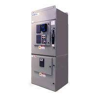
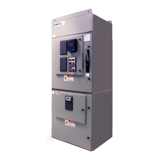
Emerson AMPGARD RVSS Instruction Booklet (169 pages)
Reduced Voltage Soft-Starter
Brand:
Emerson
| Category:
Controller
| Size: 39 MB
Table of Contents
Table of Contents
4
Section 1: Product Overview
11
Manual Objectives
11
Documentation
11
Starter Features
11
Table 1. Appendices and Subjects
11
Table 2. AMPGARD RVSS Ratings and Specifications
12
Theory of Operation
13
Starting Modes
15
Stopping Modes
16
RVSS Power and Control One-Line Diagram
17
Representative Schematic Diagrams
17
Section 2: Protection and Diagnostics
21
Signals
21
Table 4. RVSS Protection
21
Optional Motor Protective Relay
23
Monitoring
23
Communication to Other Devices
24
Trending
24
Fault Log
24
Event (Snapshot)
24
Section 3: Metering
25
Current
25
Voltage
25
Power
25
Temperature
25
Operating (System)
25
Section 4: Inputs / Outputs
26
Table 5. I/O Board Signals
26
Section 5: Communication
27
Communication between BCM, I/O Board and MUI
27
Communication Using Modbus Serial
27
Communication Using Modbus Tcp/Ethernet IP
27
Programming
28
Hardware Description
29
RVSS Enclosure and Components Arrangement
29
Power Module
32
Bypass Contactor
36
Power Supplies
36
Optional Motor Protective Relay
36
Auxiliary Interlocks
37
System Control Elements
37
Table 6. Ethernet Card Module Status (MS) Indicator
38
Table 7. Ethernet Card Network Status (NS) Indicator
38
Table 8. I/O Board Connectors J12 and J13 Signals
42
Table 9. I/O Board Status LED Functions
42
Functional Description
43
Jog
43
Normal Start
43
Coast Stop
43
Soft Stop
43
Bypass Mode
43
Commissioning Procedure
44
Preliminary Setup
44
System Characteristics Documentation
44
Programming
44
Hi-Pot and Megger Tests
44
Removing the RVSS SCR Truck
44
Programming
46
Overview
46
MUI Operations
46
Table 11. Monitoring Menu Data
48
Table 10. Setup Wizard MUI Parameters
48
Table 12. MUI PRG Menu Groups
49
Table 13. Running/Stopped/Auto LED Color Settings
51
Incontrol Installation
52
Table 14. Serial Connection Settings
56
Table 15. Ethernet Card Module Status Indicator States
72
Table 16. Ethernet Card Network Status Indicator States
73
Table 17. Login Window Fields and Buttons
73
Table 18. Start Page Functions
74
Table 19. Main Application Window Areas
75
Table 20. Quick Access Toolbar Functions
76
Example Starter Configuration Process
77
Section 10: Troubleshooting
82
10.1 Pre-Start (Power-On) Faults
82
10.2 Start Initiation Checks
83
10.2 Running Faults
84
Appendices
85
Appendix A - Modbus Register Map and Bit Assignments
86
Table 21. Modbus Register Map
86
Table 22. Active Fault/Trip - Register 312
93
Table 23. Active Warning / Alarm - Register 313
93
Table 24. Tripped Status Bits - Register 314
94
Table 25. Warning Status Bits - Register 316
94
Table 26. Motor Controller Status Bits - Register 319
95
Table 27 . Pre-Start Fault Code - Register 332
95
Table 28. System Status Bits - Register 300
96
Table 29. Start Type - Register 1018 (Profile1), 1033 (Profile 2)
96
Table 30. Decel Type - Register 1019 (Profile1), 1034 (Profile 2)
96
Table 31. MUI Control Bits - Register 1004
96
Table 32. Trigger Source Event Logger - Register 819
96
Table 33. Trigger Configuration - Register 822
96
Table 34. Trigger Command Word - Register 802
97
Table 35. Datalogger Module Status - Register 435
97
Table 36. Fault Disable Bitwise - Register 1096
97
Appendix B - Startup Documents
98
Table 37. RVSS Motor Characteristic Parameters
107
Table 38. RVSS Voltage Ramp Plus Current Limit Mode of Operation
107
Table 39. Approximate RVSS Settings for Voltage Ramp with Current Limit
107
Table 40. NEMA Locked Rotor Codes
108
Appendix C - Links to Supporting Information
109
Table 41. Reference Documents
109
Table 42. Software Links
109
Appendix D - Setup Parameter Information
110
Table 43. AMPGARD RVSS Setup Parameters or Status (See Incontrol)
111
Appendix E - Incontrol Parameter Screenshots
122
Appendix F - Motor Controller Status Codes Explanation
157
Table 44. Eight Bit Binary to Hexadecimal Converter
158
Appendix G - Incontrol Motor Control Screen
159
Appendix H - Monitoring Parameter Information
160
Table 45. Current Values
160
Table 46. Voltage Values
160
Table 47. Power Values
160
Appendix I - Motor Protective Settings
161
Appendix J - Arc Features Information
162
Appendix K - Retrofits Information
163
Appendix L - Spare Parts
164
Appendix M - Accessories
165
Notes
166
Notes
167
Advertisement
Advertisement
Related Products
Emerson Affinity
Emerson AW Series
Emerson AW28
Emerson AWN13S
Emerson AW20S
Emerson AW28S
Emerson AW20L
Emerson AW28L
Emerson Asco Advantage Series
Emerson NELSON AXPC100-CM-GP
Emerson Categories
Controller
Control Unit
Transmitter
Measuring Instruments
Fan
More Emerson Manuals
Login
Sign In
OR
Sign in with Facebook
Sign in with Google
Upload manual
Upload from disk
Upload from URL