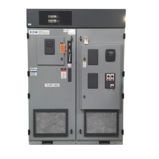
Sign In
Upload
Manuals
Brands
Eaton Manuals
DC Drives
SC9000 EP
Eaton SC9000 EP Manuals
Manuals and User Guides for Eaton SC9000 EP. We have
1
Eaton SC9000 EP manual available for free PDF download: Installation Manual
Eaton SC9000 EP Installation Manual (96 pages)
medium voltage drives
Brand:
Eaton
| Category:
DC Drives
| Size: 7.02 MB
Table of Contents
Table of Contents
5
Definitions and Symbols
11
Hazardous High Voltage
11
Warnings and Cautions
11
Glossary
13
Terms and Abbreviations
13
Chapter 1: Introduction
15
Purpose
15
Application and Description
15
SC9000 EP Standard Features
15
Revision
16
Documentation Reference
16
Eaton Contact Information
16
Chapter 2: Safety
17
Precautions
17
Safety Features
17
DC Link Capacitors
17
Grounding Practices
17
Chapter 3: Technical Data/Ratings
18
Identification
18
Table 1. Specifications
19
Table 2. Power Specifications
21
Table 3. Dimensions
22
Chapter 4: Handling, Storage, and Installation
23
General Information
23
Table 4. 2400 V AFD Typical Shipping Section Weights (Lb)
23
Table 5. 3300 V AFD Typical Shipping Section Weights (Lb)
24
Table 6. 4160 V AFD Typical Shipping Section Weights (Lb)
25
Lifting Equipment List
26
Receiving Check List
26
Long-Term Storage
26
Handling
26
Figure 1. Frame B Inverter Section, Frame C Main Disconnect and Inverter Sections, Frame D Main Disconnect, and Inverter Sections, Frame E Main Disconnect Section, and Filters
27
Figure 2. Frame a Drive and Frame B Transformer Section Overhead Lifting
28
Figure 3. Frame C, Frame D, and Frame E Transformer Section Overhead Lifting
29
Installation
30
General Information
30
Site Preparation
30
Figure 4. Frame a Drive and Frame B/C Transformer Section
30
Mounting
31
Redundant Blowers/Pull Box
31
SC9000 EP Unit Connection
31
Figure 5. Main Bus Splice
31
Figure 6. Flexible Ground Bus Link
31
Figure 7. Flexible Ground Bus Link
31
Figure 8. Ground Bus Openings
32
Figure 9. Structure Connection Detail
32
Figure 10. Transition Section
32
Figure 11. Transition Connection to Ampgard
33
Figure 12. Hardware for Transition to Ampgard
33
Figure 13. Low Voltage Pathway
33
Figure 14. Low Voltage Wireway
33
Figure 15. Low Voltage Pathway between Splits
34
Figure 16. Low Voltage Termination at Split
34
Figure 17. Main Bus Shipping Split Connection
34
Incoming Connections
35
Figure 18. Pullbox
36
Chapter 5: Arc
37
Purpose
37
Introduction
37
Table 7. SC9000 EP AR Dimensions
37
Shipping Weights
38
Connections
38
Table 8. SC9000 AR Typical Shipping Section Weights
38
Chapter 6 : Gp
39
Purpose
39
Introduction
39
Customer Supplied Power
39
Specifications
39
Table 9. GP Specification
39
Table 10. GP Power Specifications
39
Connections
40
Inverter Grounding and Replacement
40
Precautions
40
Table 11. GP Dimensions
40
Table 12. GP Shipping Weights
40
GP Inverter Removal or Installation
41
Figure 19. Fiber Optic ITG Connections
41
Figure 20. Power Supply Harness Connection
41
Figure 21. Inverter DC Cable Landings
41
Figure 22A. Inverter AC Cable Landings
42
Figure 22B. DVDT Tabs
42
Appendix A: Typical Frames A, B, C
43
SC9000 EP Configurations
43
Figure 23. Typical Schematic for SC9000 EP-Sheet 1
43
Figure 24. Typical Schematic for SC9000 EP-Sheet 2
44
Figure 25. Typical Schematic for SC9000 EP-Sheet 3
45
Figure 26. Typical Schematic for SC9000 EP-Sheet 4
46
Figure 27. Typical Schematic for SC9000 EP-Sheet 5
47
Figure 28. Frame a Parts Layout-SC9000 EP
48
Figure 29. Frame a Configuration-SC9000 EP
49
Figure 30. Frame B Parts Layout-SC9000 EP
50
Figure 31. Frame B Configuration-SC9000 EP
51
Figure 32. Frame C Parts Layout-SC9000 EP
52
Figure 33. Frame C Configuration-SC9000 EP
53
Appendix B: Typical Frames D, E
54
SC9000 EP Configurations
54
Figure 34. Typical Schematic for SC9000 EP-Sheet 1
54
Figure 35. Typical Schematic for SC9000 EP-Sheet 2
55
Figure 36. Typical Schematic for SC9000 EP-Sheet 3
56
Figure 37. Typical Schematic for SC9000 EP-Sheet 4
57
Figure 38. Typical Schematic for SC9000 EP-Sheet 5
58
Figure 39. Typical Schematic for SC9000 EP-Sheet 6
59
Figure 40. Typical Schematic for SC9000 EP-Sheet 7
60
Figure 41. Frame D Parts Layout-SC9000 EP
61
Figure 42. Frame D Configuration-SC9000 EP-2400 V
62
Figure 43. Frame D Configuration-SC9000 EP-4160 V
63
Figure 44. Frame E Parts Layout-SC9000 EP
64
Figure 45. Frame E Configuration-SC9000 EP
65
Figure 46. ARC Parts Layout-SC9000 EP
66
Figure 47. ARC, EP Frame D Configuration-SC9000 EP
67
Appendix C: Typical Frame Gp
68
SC9000 GP Configurations
68
Figure 48. Typical Schematic for SC9000 GP-Sheet 1
68
Figure 49. Typical Schematic for SC9000 GP-Sheet 2
69
Figure 50. Typical Schematic for SC9000 GP-Sheet 3
70
Figure 51. Typical Schematic for SC9000 GP-Sheet 4
71
Figure 52. Typical Schematic for SC9000 GP-Sheet 5
72
Figure 53. GP Parts Layout
73
Figure 54. SC9000 GP Configuration
74
Appendix D: Optional Equipment
75
Section 1: Introduction
75
Section 2: DV/Dt Filter
76
Figure 55. Typical DV/Dt Filter
76
Figure 56. DV/Dt Filter Effect on Drive Output
77
Figure 57. DV/Dt Filter in Cabinet
77
Figure 58. DV/Dt Representative Cabinet Outlines
78
Table 13. 2300 V DV/Dt Filters
78
Table 14. 4160 V DV/Dt Filters
78
Figure 59. DV/Dt Filter Cabinet in SC9000 EP Lineup
79
Figure 60. DV/Dt Filter Power Flow
79
Section 3: Sine Filter
80
Figure 61. Typical Sine Filter Elementary Diagram
80
Figure 62. Example before and after Sine Filter Output
80
Table 15. Replacement Parts
80
Figure 63. Sine Filter Panel Layout
81
Figure 64. Sine Filter Added to SC9000 EP Lineup
81
Figure 65. Sine Filter Power Flow One-Line Diagram
82
Figure 66. Sine Filter with Filter Fans Shown
82
Figure 67. Frame D Sine Filter
82
Table 16. 2400 V Sine Filters for Induction Motors
83
Table 17. 4160 V Sine Filters for Induction Motors
83
Section 4: Synchronous Transfer
84
Table 18. Replacement Parts
84
Figure 68. Synchronous Transfer
85
Figure 69. Synchronous Transfer Panel Layout
86
Figure 70. Synchronous Transfer Elements
87
Figure 71. AFD and Feeder Bus Energized
87
Figure 72. AFD Runs Selected Motor at Speed
87
Figure 73. Selected Motor Contactors Switching
87
Figure 74. Selected Motor on Utility Bus
88
Figure 75. Motor Select Contactor Closes
88
Figure 76. AFD Contactor Closes, Bypass Opens
88
Figure 77. Selected Motor Runs on AFD Bus
88
Section 5: Synchronous Motor System
89
Figure 78. Brush-Type Synchronous Motor Elements
89
Figure 79. Brush-Type Motor Slip Rings
89
Figure 80. Brushless Synchronous Motor Elements
89
Figure 81. SC9000 EP Brushless Synchronous Motor Control
90
Section 6: High Voltage Input
91
Figure 82. 15 Kv Input Voltage Panel Layout
91
Figure 83. High Voltage Incoming Compartment
92
Figure 84. Incoming Cable Terminations
92
Section 7: Bypass System
93
Appendix D: Optional Equipment
93
Figure 85. Representative Full Voltage Bypass Panel Layout
93
Figure 86. Normal Operation Using SC9000 EP AFD
93
Figure 87. Full Voltage Bypass Operation
93
Figure 88. Typical RVSS Cabinet
94
Figure 89. Representative RVSS Bypass Panel Layout
94
Figure 90. RVSS Bypass Normal Operation
94
Appendix D: Optional Equipment
94
Figure 91. RVSS Bypass System Bypassed
95
Advertisement
Advertisement
Related Products
Eaton SC9000 GP
Eaton Cutler-Hammer SLX9000 Series
Eaton SVX
Eaton SVX900
Eaton Cutler-Hammer Ampgard SC9000
Eaton SC100
Eaton SC300
Eaton SC200
Eaton Eaton series
Eaton SPS-2433
Eaton Categories
UPS
Circuit breakers
Industrial Equipment
Switch
Industrial Electrical
More Eaton Manuals
Login
Sign In
OR
Sign in with Facebook
Sign in with Google
Upload manual
Upload from disk
Upload from URL