Sign In
Upload
Manuals
Brands
Eaton Manuals
DC Drives
Cutler-Hammer SLX9000 Series
User Manuals: Eaton Cutler-Hammer SLX9000 Series Drives
Manuals and User Guides for Eaton Cutler-Hammer SLX9000 Series Drives. We have
2
Eaton Cutler-Hammer SLX9000 Series Drives manuals available for free PDF download: User Manual, Manual
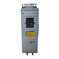
Eaton Cutler-Hammer SLX9000 Series User Manual (172 pages)
Adjustable Frequency Drives
Brand:
Eaton
| Category:
DC Drives
| Size: 8 MB
Table of Contents
Table of Contents
4
List of Figures
6
Safety
10
Definitions and Symbols
10
Hazardous High Voltage
10
Warnings, Cautions and Notices
11
Chapter 1 - Overview
15
Receiving and Inspection
15
Table 1-1: SLX9000 AF Drive Catalog Numbering System
15
Storage
16
Maintenance
16
Technical Data
16
Figure 1-1: SLX9000 Block Diagram
17
Table 1-2: 208 - 240V, NEMA Type 1 Power Ratings
18
Table 1-3: 208 - 240V, NEMA Type 12 Power Ratings
18
Table 1-4: 380 - 500V, NEMA Type 1 Power Ratings
19
Table 1-5: 380 - 500V, NEMA Type 12 Power Ratings
19
Table 1-6: 525 - 690V, NEMA Type 1 Power Ratings
20
Table 1-7: 525 - 690V, NEMA Type 12 Power Ratings
20
Table 1-8: Technical Information
21
Chapter 2 - Installation
23
Mounting
23
Figure 2-1: NEMA Type 1 and NEMA Type 12 SLX9000 Drive Dimensions, MF4 - MF6
24
Table 2-1: SLX9000 Drive Dimensions
24
Figure 2-2: SLX9000 Dimensions, NEMA Type 1 and NEMA Type
25
Table 2-2: Dimensions for SLX9000, MF4 - MF6 with Flange Kit
25
Figure 2-3: SLX9000 Dimensions, NEMA Type 1 and NEMA Type 12 with Flange Opening, MF4 - MF6
26
Table 2-3: Dimensions for the Flange Opening, MF4 - MF6
26
Figure 2-4: SLX9000 Dimensions, NEMA Type 1 and NEMA Type 12, FR7
27
Table 2-4: SLX9000 Dimensions, FR7
27
Figure 2-5: SLX9000 Dimensions, NEMA Type 1 and NEMA Type 12, FR8
28
Table 2-5: SLX9000 Dimensions, FR8
28
Figure 2-6: SLX9000 Dimensions, NEMA Types 1 and 12, FR7 and FR8
29
Table 2-6: SLX9000 Dimensions, NEMA Types 1 and 12, FR7 and FR8 with Flange Kit
29
Figure 2-7: SLX9000 Dimensions, NEMA Types 1 and 12, FR7 and FR8
30
Table 2-7: SLX9000 Dimensions, NEMA Types 1 and 12, for the Flange Opening, FR7/FR8
30
Cooling
31
Figure 2-8: Installation Space
31
Table 2-8: Mounting Space Dimensions
31
Table 2-9: Required Cooling Air
31
Changing EMC Protection Class from H to T
32
Figure 2-9: Changing of EMC Protection Class, MF4 (Left) and
32
Figure 2-10: Changing of EMC Protection Class, MF6
32
Chapter 3 - Power Wiring
33
Power Connections
33
Figure 3-1: Power Connections, MF4 - MF6
33
Figure 3-2: FR7 Power and Motor Wiring Terminals
33
Figure 3-3: FR8 Power and Motor Wiring Terminals
34
Table 3-1: Cable Types Required to Meet Standards
35
Table 3-2: Cable and Fuse Sizes - 230V Ratings
35
Table 3-3: Cable and Fuse Sizes - 480V Ratings
36
Table 3-4: Cable and Fuse Sizes - 575V Ratings
36
Figure 3-4: Cable Accessories
37
Table 3-5: Mounting Procedure
38
Installation Guidelines
40
Table 3-6: Cable Spacings
40
Figure 3-5: Stripping of Cables
41
Table 3-7: Cable Stripping Lengths
41
Figure 3-6: SLX9000, MF4
42
Figure 3-7: Cable Installation in SLX9000, MF4
42
Figure 3-8: SLX9000, MF5
43
Figure 3-9: Cable Installation in SLX9000, MF5
43
Figure 3-10: SLX9000, MF6
44
Figure 3-11: Cable Installation in SLX9000, MF6
44
Figure 3-12: SLX9000, FR7
45
Figure 3-13: Cable Installation in SLX9000, FR7
45
Figure 3-14: SLX9000, FR8
46
Figure 3-15: Cable Installation in SLX9000, FR8
46
Table 3-8: Tightening Torques of Terminals
47
Chapter 4 - Control Wiring
49
Control Unit
49
Figure 4-1: Option Board Slots D and E in Frames MF4 - MF6
49
Mf4 - Mf6 460V
49
Control Connections
50
Figure 4-2: Option Board Slots
50
Figure 4-3: Control Connections, MF4 - MF6 460V
50
Mf4 - Mf6 460V
50
Table 4-1: Multi-Control Application Default Input/Output Configuration
51
Table 4-2: AI1 Configuration, When Programmed as DIN4, MF4 - MF6 460V
51
Table 4-3: Default I/O Configuration, All 230V, FR7 - FR8 460V and All 575V
52
Table 4-4: Control Input/Output Terminal Signals, MF4 - MF6 460V
53
Table 4-5: Option Board A9 Terminal Descriptions, All 230V, FR7 - FR8
54
Figure 4-4: Jumper Selection for SLX9000, MF4 - MF6
55
Table 4-6: Option Board A2 Terminal Descriptions, All 230V, FR7 - FR8
55
Figure 4-5: Location of Jumper Blocks in the Control Board of
56
Motor Thermistor (PTC) Connection
57
Figure 4-6: Motor Thermistor (PTC) Connection
57
Chapter 5 - Menu Information
59
Keypad Operation
59
Indicators on the Keypad Display
59
Figure 5-1: Control Keypad and Drive Status Indications
59
Numeric Indicators
60
Table 5-1: Drive Status Indicators
60
Table 5-2: Control Place Indicators
60
Keypad Pushbuttons
61
Figure 5-2: Keypad Pushbuttons
61
Table 5-3: Button Descriptions
61
Menu Navigation
62
Figure 5-3: Keypad Display Data
62
Figure 5-4: Keypad Navigation Chart
63
Table 5-4: Main Menu Functions
64
Figure 5-5: Monitoring Menu
65
Table 5-5: Monitored Signals
66
Figure 5-6: Parameter Value Change Procedure
67
Figure 5-7: Selection of Control Place
68
Table 5-6: Keypad Control Menu Selections
68
Figure 5-8: Normal State, no Faults
69
Figure 5-9: Fault Display
70
Figure 5-10: Fault History Menu
70
Table 5-7: Fault Types
70
Table 5-8: System Menu Functions
71
Figure 5-11: Storing and Loading of Parameter Sets
73
Figure 5-12: Parameter Locking
74
Figure 5-13: Default Page Function
75
Figure 5-14: Timeout Time Setting
75
Figure 5-15: HMI Acknowledge Timeout
77
Figure 5-16: Mwh Counter Reset
78
Table 5-9: Counter
78
Table 5-10: Trip Counter Pages
78
Table 5-11: Software Information Pages
78
Table 5-12: Application Information Pages
79
Table 5-13: Hardware Information Pages
79
Table 5-14: Connected Options Submenu
79
Figure 5-17: Expander Board Information Menu
80
Figure 5-18: Modbus Interface
80
Table 5-15: Modbus Commands Supported by SLX9000
81
Table 5-16: Output Process Data
82
Table 5-17: Input Process Data
82
Table 5-18: Status Word
82
Table 5-19: Actual Speed
82
Table 5-20: Control Word
83
Table 5-21: Speed Reference
83
Table 5-22: Bit Definitions
83
Chapter 6 - Start-Up
85
Safety Precautions
85
Sequence of Operation
86
Start-Up Wizard
88
Figure 6-1: SLX9000 Start-Up Wizard
88
Chapter 7 - Basic Application
89
Monitoring Values (Control Keypad: Menu M1)
90
Table 7-1: Monitoring Values
90
Parameter List
91
Table 7-2: Basic Parameters (Control Keypad: Menu P2 ➔ B2.1)
91
Chapter 8 - Multi-Control Application
93
Introduction
93
Control Input/Output
95
Table 8-1: Multi-Control Application Default Input/Output Configuration
95
Table 8-2: AI1 Configuration, When Programmed as DIN4
95
Table 8-3: Default I/O Configuration, All 230V, FR7 - FR8 460V and All 575V
96
Parameter Lists
97
Monitoring Values (Control Keypad: Menu M1)
98
Table 8-4: Monitoring Values
98
Table 8-5: Basic Parameters P2.1
100
Table 8-6: Input Signals, P2.2
102
Table 8-7: Output Signals, G2.3
104
Table 8-8: Drive Control Parameters, P2.4
104
Table 8-9: Prohibit Frequency Parameters, P2.5
104
Table 8-10: Motor Control Parameters, P2.6
105
Table 8-11: Protections, P2.7
106
Table 8-12: Autorestart Parameters, P2.8
106
Table 8-13: PID Reference Parameters, P2.9
107
Table 8-14: Pump and Fan Control Parameters, P2.10
108
Table 8-15: Keypad Control Parameters, K3
108
Chapter 9 - Description of Parameters
111
Basic Parameters
111
Input Signals
116
Figure 9-1: Jumper Selections of X4/X8 When AI1 Functions as DIN4
116
Figure 9-2: AI1 Signal Selection
117
Figure 9-3: AI1 Signal Filtering
118
Output Signals
120
Figure 9-4: Without (Left) and with (Right) Reference Scaling
120
Table 9-1: Output Signals Via RO1 and Expander Board RO1, RO2 and DO1
121
Figure 9-5: Analog Output Filtering
122
Figure 9-6: Analog Output Invert
123
Figure 9-7: Analog Output Scaling
124
Table 9-2: Analog Output Scaling
124
Figure 9-8: Output Frequency Supervision
125
Drive Control
126
Figure 9-9: Relay Output 1 ON- and OFF-Delays
126
Figure 9-10: Acceleration/Deceleration (S-Shaped)
126
Figure 9-11: DC-Braking Time When Stop Mode = Coasting
128
Figure 9-12: DC-Braking Time When Stop Mode = Ramp
128
Prohibit Frequencies
129
Figure 9-13: DC Braking Time at Start
129
Figure 9-14: Prohibit Frequency Area Setting
130
Figure 9-15: Ramp Speed Scaling between Prohibit Frequencies
130
Motor Control
131
Figure 9-16: Linear and Squared Change of Motor Voltage
131
Figure 9-17: Programmable Vhz Curve
132
Protections
133
Figure 9-18: Motor Cooling Power
136
Figure 9-19: Motor Temperature Calculation
137
Figure 9-20: Stall Characteristics Settings
138
Figure 9-21: Stall Time Count
138
Figure 9-22: Setting of Minimum Load
140
Figure 9-23: Underload Time Counter Function
140
Auto Restart Parameters
141
Figure 9-24: Automatic Restart
142
PID Reference Parameters
143
Figure 9-25: PID Controller Function as I-Controller
144
Figure 9-26: PID Output Curve with the Values of Example 2
145
Figure 9-27: PID Output with the Values of Example 3
146
Figure 9-28: Example of Actual Value Signal Scaling
147
Figure 9-29: Sleep Function
148
Table 9-3: Selectable Wake-Up Functions
149
Pump and Fan Control
150
Table 9-4: PFC-Control Input/Output Configuration with Three Pumps, MF4 - MF6 460V
152
Figure 9-30: 3-Pump Autochange System, Principal Control Diagram
153
Figure 9-31: Example of 3-Pump Autochange, Main Diagram
153
Table 9-5: PFC-Control Input/Output Configuration with Two Pumps, MF4 - MF6 460V
154
Figure 9-32: 2-Pump Autochange System, Principal Control Diagram
155
Figure 9-33: Example of 2-Pump Autochange, Main Diagram
155
Figure 9-34: Autochange Applied to Auxiliary Drives Only
156
Figure 9-35: Autochange with All Drives
157
Figure 9-36: Autochange Interval and Limits
158
Keypad Control Parameters
159
Control Signal Logic
160
Figure 9-37: Control Signal Logic of the Multi-Control Application
160
Appendix A - Fault Codes
161
Table A-1: Fault Codes
161
Appendix B - Expander Board Optaa
165
Description of Expander Board OPTAA
165
I/O Terminals on OPTAA
165
Figure B-1: Expander Board OPTAA
165
Table B-1: I/O Terminals of Board OPTAA
165
Appendix C - Expander Board Optai
167
Description of Expander Board OPTAI
167
I/O Terminals on OPTAI
167
Figure C-1: Expander Board OPTAI
167
Table C-1: I/O Terminals of Board OPTAI
167
Appendix D - Option Board Kits
169
230V, FR7 - FR8 460V and 575V Drives
169
Figure D-1: Option Boards
169
Table D-1: Option Board Kits
169
Advertisement
Eaton Cutler-Hammer SLX9000 Series Manual (24 pages)
Adjustable Frequency Drives
Brand:
Eaton
| Category:
DC Drives
| Size: 0 MB
Table of Contents
Table of Contents
1
SLX9000 Open Drives Product Description
2
Features
2
Technical Data and Specifications
3
Catalog Number Selection
4
Product Selection
5
Options
7
Accessories
8
Dimensions
9
Replacement Parts
11
SLX9000 Enclosed Drives Product Description
12
Features
12
Standards and Certifications
12
Technical Data and Specifications
13
Catalog Number Selection
14
Product Selection
17
Dimensions
19
Advertisement
Related Products
Eaton SC9000 EP
Eaton SC9000 GP
Eaton SVX
Eaton SVX900
Eaton Cutler Hammer PowerXL DC1 E1 Series
Eaton SLX
Eaton CEAG SL 3301
Eaton CEAG SL 3301 CG-S
Eaton HALO SLD6 WH Series
Eaton Cooper Lighting SLD6 Series
Eaton Categories
UPS
Circuit breakers
Switch
Industrial Equipment
Industrial Electrical
More Eaton Manuals
Login
Sign In
OR
Sign in with Facebook
Sign in with Google
Upload manual
Upload from disk
Upload from URL