Sign In
Upload
Manuals
Brands
Eaton Manuals
DC Drives
PowerXL DH1
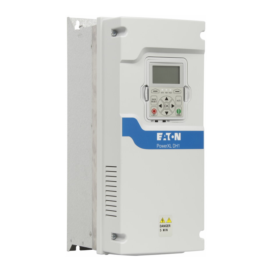
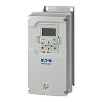
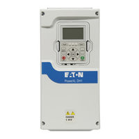
Eaton PowerXL DH1 Manuals
Manuals and User Guides for Eaton PowerXL DH1. We have
6
Eaton PowerXL DH1 manuals available for free PDF download: Communications Manual, Applications Manual, Installation Manual, Quick Start Manual, Instruction Leaflet, Manual
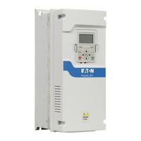
Eaton PowerXL DH1 Applications Manual (240 pages)
VFD
Brand:
Eaton
| Category:
DC Drives
| Size: 1 MB
Table of Contents
Table of Contents
4
Before Commencing the Installation
15
Definitions and Symbols
16
Hazardous High Voltage
16
Warnings and Cautions
16
Important Safety Information
17
CHAPTER 1-Powerxl DH1 Series Overview
25
How to Use this Manual
25
Receiving and Inspection
25
Real Time Clock Battery Activation
25
Figure 1. RTC Battery Connection
25
Table 1. Common Abbreviations
25
Rating Label
26
Carton Labels (U.S. and Europe)
26
Figure 2. Rating Label
26
Figure 3. Rating Label
26
Catalog Number System
27
Figure 4. Catalog Numbering System
27
Power Ratings and Product Selection
28
Table 2. Open Type /IP20
28
Table 3. Type 1/IP21
28
Table 4. Type 12/IP54
28
Table 5. Open Type/Ip20
29
Table 6. Type 1/IP21
29
Table 7. Type 12/IP54
30
Table 8. Type 1/IP21
30
Table 9. Type 12/IP54
31
Chapter 2-Keypad Overview
32
Figure 5. Keypad and Display
32
Keypad Buttons
33
Table 10. Keypad Buttons
33
LED Lights
35
LCD Display
35
Figure 6. General View of LCD
35
Figure 7. Welcome Page
35
Table 11. LED State Indicators
35
Figure 8. Upgrade Page
36
Figure 9. Auto Backup Page
36
Figure 10. Main Menu
36
Table 12. Soft Keys
36
Figure 11. Parent Node Page
37
Figure 12. Parameter Page
37
Figure 13. Parameter Page from Favorite Menu
37
Figure 14. Fault Page
37
Chapter 3-Menu Overview
38
Main Menu Page
38
Menu Navigation
38
Figure 15. Main Menu Page
38
Figure 16. Main Menu Navigation
38
Menu Structure
39
Table 13. Keypad Menus
39
M-Monitor
40
Figure 17. M-Monitor
40
F-Fault
41
Figure 18. Active Faults
41
Pop-Up Fault
42
Figure 19. Pop-Up Active Faults
42
Fault History
43
Figure 20. Fault History
43
Fault Log
44
P-Parameter
44
Figure 21. Parameter Setting
44
Figure 22. Parameter Sets
45
Figure 23. down from Keypad
46
Figure 24. Parameters Comparison
47
Figure 25. Password
48
Value Edit
49
Figure 26. Edit Parameter Value
49
T-Favorite
50
Figure 27. Parameter Locked
50
Chapter 4-Startup
51
Startup Wizard Page
51
Startup Wizard
51
Table 14. Startup Wizard Instructions
51
PID Mini-Wizard
52
Table 14. Startup Wizard Instructions Continued
52
Table 15. PID Mini-Wizard Values
52
Chapter 5-Basic Application
53
I/O Controls
53
Force Open/Force Close Selection
54
DIGIN Selection
54
Option Board Digin Selection
54
Basic Application Control I/O Configuration
55
Table 16. I/O Connection
55
Table 17. Drive Communication Ports
56
Control I/O Configuration
57
Basic Application-Parameters List
57
Monitor
57
Table 18. Basic-M1
57
Table 19. IO Status-M2
57
Table 20. Optional Boards - M3
57
Table 21. Energy Savings - M4
58
Table 22. FB Monitor Menu - M5
58
Table 23. User Defined Output - M8
59
Table 24. MWH Monitor - M9
59
Table 25. Multi-Monitoring - M11
59
Parameters
60
Inputs
60
Table 26. Basic Parameters - P1
60
Table 27. Basic Setting - P2.1
60
Table 28. Digital Input - P2.2
61
Table 29. Preset Speed - P2.3
63
Table 30. AI1 Settings - P2.4
63
Table 31. AI2 Settings - P2.5
63
Outputs
64
Table 32. Digital Output - P3.1
64
Table 33. Supervisions - P3.2
65
Drive Control
66
Table 34. Analog Output 1 - P3.3
66
Table 35. Analog Output 2 - P3.4
66
Table 36. Basic Setting - P4.1
66
Table 37. Brake - P4.2
67
Table 38. Skip Frequency - P4.3
67
Table 39. Analog Output 2 - P3.4
67
Motor Control
68
Protections
68
Table 40. Basic Setting - P5.1
68
Table 41. Motor - P6.1
68
Table 42. Drive - P6.2
70
Table 43. Communication - P6.3
71
Table 44. Auto Restart - P6.4
71
Table 45. Fire Mode - P9
71
Communication
72
Table 46. Basic Setting - P10.1
72
Table 47. FB Process Data Input Sel - P12.1
72
Table 48. FB Process Data Output Sel - P12.2
73
RS485 Bus
74
Table 49. Basic Setting - P12.3.1
74
Table 50. Modbus RTU - P12.3.2
74
Table 51. Bacnet MS/TP - P12.3.3
74
Ethernet Bus
75
Table 52. Basic Setting - P12.4.1
75
Table 53. Modbus TCP - P12.4.2
75
Table 54. Bacnet IP - P12.4.3
75
System
76
Table 55. Basic Setting - P13.1
76
Table 56. Version Info - P13.2
77
Table 57. Application Info - P13.3
77
Table 58. User Info - P13.4
78
Table 59. Operate Mode - O
78
Chapter 6 - PID Application
79
Introduction
79
I/O Controls
79
Force Open/Force Close Selection
80
DIGIN Selection
80
Option Board Digin Selection
80
Timer Channel Selection
80
Control I/O Configuration
81
Table 60. PID Application Default I/O Connection
81
PID Application-Parameters List
82
Table 61. Drive Communication Ports
82
Table 62. Basic - M1
83
Table 63. IO Status - M2
83
Table 64. Optional Boards - M3
83
Table 65. Energy Savings - M4
83
Table 66. FB Monitor Menu - M5
84
Table 67. PID Monitor - M6
85
Table 68. Timer/Interval Control - M7
86
Table 69. User Defined Output - M8
86
Table 70. MWH Monitor - M9
86
Table 71. Multi-Monitoring - M11
86
Parameters
87
Inputs
87
Table 72. Basic Parameters - P1
87
Table 73. Basic Setting - P2.1
87
Table 74. Digital Input - P2.2
88
Table 75. Preset Speed - P2.3
90
Table 76. AI1 Settings - P2.4
90
Table 77. AI2 Settings - P2.5
90
Outputs
91
Table 78. Digital Output - P3.1
91
Table 79. Supervisions - P3.2
92
Table 80. Analog Output 1 - P3.3
93
Drive Control
94
Table 81. Analog Output 2 - P3.4
94
Table 82. Basic Setting - P4.1
94
Motor Control
95
Table 83. Brake - P4.2
95
Table 84. Skip Frequency - P4.3
95
Table 85. Energy Savings Calc - P4.4
95
Table 86. Basic Setting - P5.1
95
Protections
96
Table 87. Second Motor Parameter - P5.2
96
Table 88. Motor - P6.1
96
Table 89. Drive - P6.2
98
Table 90. Communication - P6.3
98
Table 91. Auto Restart - P6.4
99
Table 92. Basic Setting - P7.1
99
Setpoint
100
Table 93. Monitor - P7.2
100
Table 94. Basic - P7.3.1
100
Table 95. Setpoint 1 - P7.3.2
101
Table 96. Setpoint 2 - P7.3.3
101
Feedback
102
Table 97. Basic - P7.4.1
102
Table 98. Feedback 1 - P7.4.2
102
Table 99. Feedback 2 - P7.4.3
102
Feedforward
103
PID Controller 2
103
Table 100. Basic - P7.5.1
103
Table 101. Feedforward 1 - P7.5.2
103
Table 102. Feedforward 2 - P7.5.3
103
Table 103. Basic Setting - P8.1
103
Setpoint
104
Table 104. Monitor - P8.2
104
Table 105. Basic - P8.3.1
104
Table 106. Setpoint 1 - P8.3.2
104
Feedback
105
Table 107. Setpoint 2 - P8.3.3
105
Table 108. Basic - P8.4.1
105
Table 109. Feedback 1 - P8.4.2
105
Table 110. Feedback 2 - P8.4.3
105
Feedforward
106
Table 111. Basic - P8.5.1
106
Table 112. Feedforward 1 - P8.5.2
106
Table 113. Feedforward 2 - P8.5.3
106
Table 114. Fire Mode - P9
106
Bypass
107
Table 115. Basic Setting - P10.1
107
Table 116. Redundant Drive - P10.2
107
Real Time Clock
108
Table 117. Interval 1 - P11.1
108
Table 118. Interval 2 - P11.2
108
Table 119. Interval 3 - P11.3
108
Table 120. Interval 4 - P11.4
108
Communication
109
Table 121. Interval 5 - P11.5
109
Table 122. Timer - P11.6
109
Table 123. FB Process Data Input Sel - P12.1
109
Table 124. FB Process Data Output Sel - P12.2
110
RS485 Bus
111
Table 125. Basic Setting - P12.3.1
111
Table 126. Modbus RTU - P12.3.2
111
Ethernet Bus
112
Table 127. Bacnet MS/TP - P12.3.3
112
Table 128. Basic Setting - P12.4.1
112
Table 129. Modbus TCP - P12.4.2
112
System
113
Table 130. Bacnet IP - P12.4.3
113
Table 131. Basic Setting - P13.1
113
Table 132. Version Info - P13.2
115
Table 133. Application Info - P13.3
115
Table 134. User Info - P13.4
115
Table 135. Operate Mode - O
115
Chapter 7-Advanced Application Parameter
116
I/O Controls
116
Force Open/Force Close Selection
117
DIGIN Selection
117
Option Board Digin Selection
117
Timer Channel Selection
117
Control I/O Configuration
118
Table 136. Advanced Application Default I/O Configuration
118
Table 137. Drive Communication Ports
119
Advanced Application-Parameters List
120
Monitor
120
Table 138. Basic - M1
120
Table 139. IO Status - M2
120
Table 140. Optional Boards - M3
121
Table 141. Energy Savings - M4
121
Table 142. FB Monitor Menu - M5
121
Table 143. PID Monitor - M6
122
Parameters
123
Table 144. Timer/Interval Control - M7
123
Table 145. User Defined Output - M8
123
Table 146. MWH Monitor - M9
123
Table 147. Multi-Monitoring - M11
123
Table 148. Basic Parameters - P1
123
Table 149. Basic Setting - P2.1
124
Table 150. Digital Input - P2.2
125
Table 151. Preset Speed - P2.3
127
Table 152. Preset Speed - P2.3
127
Table 153. Preset Speed - P2.3
127
Outputs
128
Table 154. Digital Output - P3.1
128
Table 155. Supervisions - P3.2
129
Table 156. Supervisions - P3.2
130
Table 157. Analog Output 2 - P3.4
131
Table 158. Logic Function - P3.5
131
Drive Control
132
Table 159. Basic Setting - P4.1
132
Motor Control
133
Table 160. Brake - P4.2
133
Table 161. Skip Frequency - P4.3
133
Table 162. Energy Savings Calc - P4.4
133
Table 163. Basic Setting - P5.1
133
Protections
134
Table 164. Second Motor Parameter - P5.2
134
Table 165. Motor - P6.1
134
Table 166. Drive - P6.2
135
Table 167. Communication - P6.3
136
Table 168. Auto Restart - P6.4
136
PID Controller 1
137
Table 169. Basic Setting - P7.1
137
Setpoint
138
Table 170. Monitor - P7.2
138
Table 171. Basic - P7.3.1
138
Table 172. Setpoint 1 - P7.3.2
139
Table 173. Setpoint 2 - P7.3.3
139
Feedback
140
Feedforward
140
Table 174. Basic - P7.4.1
140
Table 175. Feedback 1 - P7.4.2
140
Table 176. Feedback 2 - P7.4.3
140
Table 177. Basic - P7.5.1
140
PID Controller 2
141
Table 178. Feedforward 1 - P7.5.2
141
Table 179. Feedforward 2 - P7.5.3
141
Table 180. Basic Setting - P8.1
141
Setpoint
142
Table 181. Monitor - P8.2
142
Table 182. Basic - P8.3.1
142
Table 183. Setpoint 1 - P8.3.2
142
Feedback
143
Table 184. Setpoint 2 - P8.3.3
143
Table 185. Basic - P8.4.1
143
Table 186. Feedback 1 - P8.4.2
143
Table 187. Feedback 2 - P8.4.3
143
Feedforward
144
Table 188. Basic - P8.5.1
144
Table 189. Feedforward 1 - P8.5.2
144
Table 190. Feedforward 2 − P8.5.3
144
Table 191. Fire Mode − P9
144
Bypass
145
Real Time Clock
145
Table 192. Basic Setting - P10.1
145
Table 193. Redundant Drive - P10.2
145
Table 194. Interval 1 - P11.1
145
Table 194. Interval 1 - P11.1, Continued
146
Table 195. Interval 2 - P11.2
146
Table 196. Interval 3 - P11.3
146
Table 197. Interval 4 - P11.4
146
Table 198. Interval 5 - P11.5
146
Communication
147
Table 199. Timer - P11.6
147
Table 200. FB Process Data Input Sel - P12.1
147
Table 201. FB Process Data Output Sel - P12.2
147
RS485 Bus
148
Table 202. Basic Setting - P12.3.1
148
Table 203. Modbus RTU - P12.3.2
148
Ethernet Bus
149
Table 204. Bacnet MS/TP - P12.3.3
149
Table 205. Basic Setting - P12.4.1
149
Table 206. Modbus TCP - P12.4.2
149
System
150
Table 207. Bacnet IP - P12.4.3
150
Table 208. Basic Setting - P13.1
150
Table 209. Version Info - P13.2
152
Table 210. Application Info - P13.3
152
Table 211. User Info - P13.4
152
Table 212. Operate Mode - O
152
Advertisement
Eaton PowerXL DH1 Communications Manual (256 pages)
VFD
Brand:
Eaton
| Category:
DC Drives
| Size: 3 MB
Table of Contents
Table of Contents
4
Safety
13
Before Commencing the Installation
13
Definitions and Symbols
14
Warnings and Cautions
14
Motor and Equipment Safety
17
Powerxl Series Overview
25
How to Use this Manual
25
Receiving and Inspection
25
Real Time Clock Battery Activation
25
Figure 1. RTC Battery Connection
25
Table 1. Common Abbreviations
25
Rating Label
26
General Information
26
Figure 2. Rating Label (DG1)
26
Figure 3. Rating Label (DH1)
26
Option Card Slots
27
Figure 4. Powerxl Series Control Board Location
27
Figure 5. Count
27
Figure 5. Powerxl Series Control Board Location
27
Control Wiring
28
Installing Powerxl Series Option Board
28
Table 2. Wire Sizes
28
Control Cable Grounding
29
EMC Directive
29
Figure 6. Control Cable Grounding
29
Table 3. Control Wiring Requirements
29
Table 4. Powerxl Series-Drive Option Boards
29
Table 5. Powerxl Series Drives Protocols
29
Modbus Rtu On-Board Communications
30
Modbus RTU Specifications
30
Figure 7. Connection Diagram
30
Figure 8. Terminal Wiring
30
Table 6. Connections
30
Table 7. Communications
30
Commissioning
31
Figure 9. Termination Resistor and Shielding
31
Figure 10. DG1 Keypad Navigation to RS-485 Menu
31
Figure 11. DH1 Keypad Navigation to RS-485 Menu
32
Table 8. Modbus RTU
32
Modbus Communication Standards
33
Figure 12. the Basic Structure of a Modbus Frame
33
Table 9. Functions
34
Table 10. Request to Read Coils
34
Table 11. Request to Read Discrete Inputs
34
Table 12. Request to Read Holding Registers
34
Table 13. Request to Read Input Registers
34
Table 14. Request to Read Exception Status
35
Table 15. Read Diagnostics
35
Table 16. Request to Write Single Coil
35
Table 17. Request to Write Single Register
35
Table 18. Write Coils 19-28
35
Table 19. Request to Write Holding Registers
35
Table 20. Index Table
36
Table 21. Process Data Slave
36
Master (Max. 22 Bytes)
36
Table 22. Process Data Master
36
Slave (Max. 22 Bytes)
36
Table 23. Fieldbus Basic Input Table
37
Table 24. FB Control Word
37
Process Data out
38
Table 25. Fieldbus Basic Output Table
38
Table 26. FB Status Word Bit Descriptions
38
Table 27. FB General Status Word
38
Table 28. Process Data out
39
Table 29. Process Data in
39
Modbus Tcp On-Board Communications
40
Modbus/Tcp Specifications
40
Hardware Specifications
40
Table 30. Modbus/Tcp Technical Data
40
Table 31. Ethernet LED Description
40
Figure 13. Module and Network Status
41
Table 32. Module Status LED Description
41
Table 33. Network Status LED Description
41
Commissioning
42
Figure 14. CAT-5E Cable
42
Figure 15. DG1 Keypad Navigation to Ethernet Comm Settings
42
Figure 16. DH1 Keypad Navigation to Ethernet Comm Settings
43
Table 35. Ethernet/Ip / Modbus TCP-P20.3, Continued
44
Figure 17. DG1 Static IP Mode
45
Figure 18. DH1 Static IP Mode
46
Figure 19. DG1 Static IP Address
47
Figure 20. DH1 Static IP Address
48
Modbus Communication Standards
49
Table 36. Request to Read Coils
49
Table 37. Request to Read Discrete Inputs
49
Table 38. Request to Read Holding Registers
49
Table 39. Request to Read Input Registers
49
Table 40. Request to Read Exception Status
49
Table 41. Read Diagnostics
49
Table 42. Request to Write Single Coil
50
Table 43. Request to Write Single Register
50
Table 44. Write Coils 19-28
50
Table 45. Write Holding Registers
50
Table 46. Index Table
50
Table 47. Process Data Slave
51
Master (Max. 22 Bytes)
51
Table 48. Process Data Master
51
Slave (Max. 22 Bytes)
51
Table 49. Fieldbus Basic Input Table
51
Table 50. Table 55. FB Control Word
52
Table 51. Table 57 . Fieldbus Basic Output Table
53
Table 52. Table 59. FB Status Word Bit Descriptions
53
Table 53. Table 60. FB General Status Word
53
Table 54. Process Data out
54
Table 55. Process Data in
54
Ethernet/Ip On-Board Communications
55
Ethernet/Ip Specifications
55
Table 56. Ethernet/Ip Technical Data
55
Hardware Specifications
56
Table 57. Ethernet LED Description
56
Figure 21. Module and Network Status
57
Table 58. Module Status LED Description
57
Table 59. Network Status LED Description
57
Ethernet/Ip Overview
58
Table 60. Ethernet/Ip Network Settings
59
Commissioning
60
Figure 25. DG1 Static IP Mode
61
PLC Programming
63
Table 61. List of Object Classes
73
Table 62. Services Supported by Object Classes
74
Table 63. Elementary Data Types
74
Table 64. Constructed Data Types
74
Table 65. Different Types of Resets Supported by the Identity Object
74
Table 66. Identity Object
75
Table 67. Connection Manager Object
76
Table 68. TCP/IP Interface Object
77
Table 69. Ethernet Link Object
78
Table 70. Assembly Object
79
Table 71. Motor Data Object
80
Table 72. Control Supervisor Object
81
Figure 27. State Transition Diagram
82
Table 73. Motor Data Object
83
Table 74. Vendor Specific Objects
84
Table 75. Instance 20 (Output) Length = 4 Bytes
85
Table 76. Instance 21 (Output) Length = 4 Bytes
85
Table 77. Instance 23 (Output) Length = 6 Bytes
85
Table 78. Instance 25 (Output) Length = 6 Bytes
85
Table 79. Instance 101 (Output) Length = 8 Bytes
86
Table 80. Instance 111 (Output) Length = 20 Bytes
87
Table 81. Instance 70 (Input) Length = 4 Bytes
88
Table 82. Instance 71 (Input) Length = 4 Bytes
88
Table 83. Instance 73 (Input) Length = 6 Bytes
89
Table 84. Instance 75 (Input) Length = 6 Bytes
89
Table 85. Instance 107 (Input) Length = 8 Bytes
89
Table 86. Instance 117 (Input). EIP Drive Status Length = 34 Bytes
90
Table 87. Instance 127 (Input). EIP Drive Status Length = 20 Bytes
91
Table 88. Instance 128 (Input). EIP Drive Status Length = 20 Bytes
91
Bacnet Ms/Tp-On-Board Communication
92
Bacnet MS/TP Connections
92
Figure 28. Principal Example Diagram
92
Table 89. Bacnet MS/TP Technical Data
92
Figure 29. Stripping the Cable
93
Figure 30. RS-485 Cable Strip (Aluminum Shield)
93
Figure 31. Drive Terminals (Bacnet)
93
Figure 32. Serial Ground
93
Figure 33. RS-485 Bus Termination Setup
94
Figure 34. Bacnet Bus Termination
94
Commissioning
95
Figure 35. Powerxl DG1 Bacnet MSTP Parameter Navigation
95
Figure 36. Powerxl DH1 Bacnet MSTP Parameter Navigation
96
Table 90. Bacnet MS/TP Parameter Table
96
Bacnet Overview
97
Table 91. Supported Object Types and Properties Summary
98
Table 92. Binary Value Object Instance Summary
101
Table 93. Analog Value Object Instance Summary
102
Table 94. Analog Input Object Instance Summary
102
Figure 37. Fault Tracing
103
Table 95. Multi State Object Instance Summary
103
Table 96. Analog Input Object Instance Summary
103
Profibus-Dp External Communication Cards
104
PROFIBUS Specifications
104
Table 97 . PROFIBUS Technical Data
104
Table 98. Line Length
104
Hardware Specifications
105
Figure 38. Com1 PROFIBUS Card Layout
105
Table 99. PROFIBUS Leds
105
PROFIBUS Cable
106
Figure 39. Com1 PROFIBUS DB9 Adapter
106
Table 100. Connector and Pin Assignment
106
Table 101. PROFIBUS Cable Connections
106
Table 102. Recommended Cable
106
Commissioning
107
Figure 40. PROFIBUS Parameter Menu
107
PROFIBUS-Powerxl Series
109
Table 103. PROFIBUS Parameters
110
Table 104. Binary Bits and Corresponding Outputs
111
Table 105. Bypass Mode Process Data Modules
111
Table 106. Fieldbus Basic Output Table
111
PROFIBUS Overview
112
Figure 41. Profidrive
112
Figure 42. Application Class
113
Table 107. Application Class
113
Table 108. Profidrive Control Word 1-STW1 Message Examples
114
Table 109. Control Word (STW1) Message Examples
116
Table 110. Application Status Word Profidrive
116
Table 111. References
117
Figure 43. General State Diagram
118
Table 112. PROFIBUS Option Card
119
Table 113. Standard Telegram 1
119
Table 114. Words and Double Words
120
Table 115. Base Mode Parameter Request
120
Table 116. Base Model Response
120
Table 117. Field Coding
121
Canopen External Communication Cards
123
Canopen Technical Data
123
Canopen Cable
123
Table 118. Canopen Connections
123
Table 119. Communications
123
Table 120. Environment
123
Table 121. Practical Bus Length
123
Canopen Bus Termination
124
Figure 44. Canopen Bus Termination
124
Hardware Specification
125
Figure 45. Canopen Hardware
125
Table 122. Power LED (D1) Red LED
125
Table 123. Canopen Board Status LED (D10) (Red LED)
125
Table 124. Canopen Module Status-Error LED (D2-Red LED)
125
Table 125. Canopen Module Status-Run LED (D2-Green LED)
125
Commissioning
126
Figure 46. Canopen Parameters
126
Table 126. Canopen Parameters
127
Canopen Overview
128
Table 127. Message Frame
128
Table 128. Predefined Connection Set
129
Network Management (NMT)
130
Figure 47. NMT State Machine
130
Table 129. Start Remote Node Message
131
Table 130. Stop Remote Node Message
131
Table 131. Enter Pre-Operational Message
131
Table 132. Reset Node Message
131
Table 133. Reset Communication Message
131
Drive Profile State Machine
132
Figure 48. Internal State Machine
132
Device Profile Parameters
133
Table 134. Device Profile Parameters Index
133
Table 135. 0X6040 Control Word
134
Table 136. 0X6041 Status Word
135
Table 137. Process Data (PDO)
136
Table 138. Fixed Control Word
137
Table 139. Fixed Status Word
138
Object Directory
139
Table 140. Object Directory Index
139
Table 141. Service Data (SDO)
141
Table 142. Process Data Application Mapping Index
142
Figure 49. Device Profile
144
Devicenet External Communication Cards
145
Devicenet Technical Data
145
Table 143. Devicenet Connection
145
Table 144. Communications
145
Table 145. Environment
145
Figure 50. Trunk Lines or Drop Lines
146
Figure 51. Devicenet Hardware
146
Devicenet Board LED Status
147
Table 146. Devicenet Power LED (D1)
147
Table 147. Devicenet Board Status LED (D10)
147
Table 148. the MS and NS LED (D2)
147
Commissioning
148
Figure 52. Module and Network Status
148
Table 149. Module Status LED Description
148
Table 150. Network Status LED Description
148
Figure 53. Devicenet Parameters
149
Devicenet Overview
150
Table 151. Devicenet Parameters
150
Table 152. Instance 20 (Output) Length = 4 Bytes
151
Table 153. Instance 21 (Output) Length = 4 Bytes
151
Table 154. Instance 23 (Output) Length = 6 Bytes
151
Table 155. Instance 25 (Output) Length = 6 Bytes
151
Table 156. Instance 101 (Output) Length = 8 Bytes
152
Table 157. Instance 111 (Output) Length = 20 Bytes
153
Table 158. Instance 70 (Input) Length = 4 Bytes
154
Table 159. Instance 71 (Input) Length = 4 Bytes
154
Table 160. Instance 73 (Input) Length = 6 Bytes
155
Table 161. Instance 75 (Input) Length = 6 Bytes
155
Dn_Non_Existant
155
0X01 DN_STARTUP
155
Dn_Not_Ready
155
0X03 DN_READY
155
0X04 DN_ENABLED
155
0X05 DN_STOPPING
155
Dn_Fault_Stop
155
0X07 DN_FAULTED
155
Table 162. Instance 107 (Input) Length = 8 Bytes
156
Table 163. Instance 117 (Input). EIP Drive Status Length = 34 Bytes
157
Table 164. Instance 127 (Input). EIP Drive Status Length = 20 Bytes
158
Figure 54. Network State Machine
159
Table 165. List of Object Classes
159
Table 166. List of Services
160
Table 167. List of Data Types
160
Table 168. Reset Service
161
Table 169. Identity Object, Class 0X01
161
Table 170. Bit Definitions for Status Instance Attribute of Identity Object
162
Table 171. Values for Extended Device Status Field (Bits 4-7) in Status Instance Attribute
162
Table 172. Connection Object, Class 0X05
163
Table 173. Devicenet Object, Class 0X03
164
Table 174. Assembly Object, Class 0X04
165
Table 175. Motor Data Object, Class 0X28
166
Table 176. Control Supervisor Object, Class 0X29
167
Table 177. AC/DC Drive Object, Class 0X2A
168
Table 178. Vendor Parameters Object, Class 0Xa0, 0Xa1, 0Xa2, 0Xa3
169
Table 179. Base Device Information Object
170
Smartwire-Dt External Communication Cards
171
Table 180. Smartwire-DT Technical Data
171
Table 181. Line Length
171
Figure 55. Smartwire-DT "DXG-NET-SWD-IP20" Module Details
172
Figure 56. Smartwire-DT "DXG-NET-SWD-IP54" Module Details
172
Hardware Specifications
172
Smartwire-DT
172
Table 182. Smartwire-DT Diagnostic LED
172
Figure 57. 8 Core Flat Cable and Pin Assignment
173
Figure 58. 5 Core Round Cable and Pin Assignment
173
Figure 59. External Device Plug SWD4-8SF2-5
174
Smartwire-DT Cable
174
Table 183. Recommendation for 8 Core Flat Cable
174
Table 184. Recommendation for 5 Core Round Cable
174
Table 185. Firmware Versions of Smartwire-DT Gateways
174
Table 186. Compatible Field Bus Description Files
174
Figure 60. Connection of Smartwire-DT Module to Powerxl DG1 Drive
175
Figure 61. Mounting of Smartwire-DT "DXG-NET-SWD-IP20" Module on Powerxl DG1 Drive
176
Figure 62. Connection of Flat Cable with Smartwire-DT "DXG-NET-SWD-IP20" Module
176
Figure 63. Mounting of Smartwire-DT "DXG-NET-SWD-IP54" Module on Powerxl DG1 Drive
176
Figure 64. Connection of Round Cable with Smartwire-DT "DXG-NET-SWD-IP54" Module
176
Installation
176
Commissioning
177
Figure 67. Recommended Wire Lengths
177
Table 187. Recommended Cable Lengths
177
Figure 68. Smartwire-DT Parameter Menu
178
Smartwire-DT Parameters
178
Table 188. Smartwire-DT Parameters
179
Smartwire-DT - Powerxl Series
181
Cyclic Data
182
Table 189. Cyclic Profile Data
182
Table 190. Profile 1: Input Bytes 0 and 1
182
Table 191. Profile 1: Output Bytes 0 and 1
183
Table 193. Profile 2: Output Bytes 0 and 4
185
Table 194. References Table for Setpoint/Actual Speed
186
Smartwire-DT Diagnostics
187
Table 195. Diagnostic Alarms of the Powerxl DG1 Variable Frequency Drive
187
Eaton PowerXL DH1 Installation Manual (128 pages)
Variable Frequency Drive
Brand:
Eaton
| Category:
DC Drives
| Size: 7 MB
Table of Contents
Table of Contents
4
Before Commencing the Installation
9
Definitions and Symbols
10
Hazardous High Voltage
10
Warnings and Cautions
10
Motor and Equipment Safety
13
Chapter 1-Powerxl Series Overview
21
How to Use this Manual
21
Receiving and Inspection
21
Real Time Clock Battery Activation
21
Figure 1. RTC Battery Connection
21
Table 1. Common Abbreviations
21
Rating Label
22
Carton Labels (U.S. and Europe)
22
Figure 2. Rating Label-DG1
22
Figure 3. Rating Label-DH1
22
Figure 4. Carton Label-DG1
22
Figure 5. Carton Label-DH1
22
Catalog Number System
23
Figure 6. Catalog Numbering System
23
Power Ratings and Product Selection
24
Table 2. Open Type IP20
24
Table 3. Type 1/IP21
24
Table 4. Type 12/IP54
25
Table 5. Open Type IP20
25
Table 6. Type 1/IP21
26
Table 7. Type 12/IP54
26
Table 8. Type 1/IP21
27
Table 9. Type 12/IP54
27
DG1 Replacement Parts
28
Table 10. Frame 0
28
Table 11. Frame 1
28
Table 12. Frame 2
29
Table 13. Frame 3
29
Table 14. Frame 4
30
Table 15. Frame 5
31
Table 16. Frame 6
32
DH1 Replacement Parts
33
Table 17 . Frame 1
33
Table 18. Frame 2
33
Table 19. Frame 3
33
Table 20. Frame 4
34
Table 21. Frame 5
34
Table 22. Frame 6
34
Chapter 2-Engineering Considerations
35
Introduction
35
Figure 7 . Drive System (PDS = Power Drive System)
35
Table 23. Drive System Components
35
Electrical Power Network
36
Input Voltage and Frequency
36
Input Voltage Balance
36
Figure 8. AC Power Networks with Grounded Neutral Point (TN-/TT Networks)
36
Total Harmonic Distortion (THD)
37
Reactive Power Compensation Devices
37
Chapter 3-Product Overview
38
Component Identification
38
Figure 10. Block Diagram, Elements of Powerxl Frequency Inverters
39
Table 24. Elements of Powerxl Frequency Inverters
39
Selection Criteria
40
Proper Use
40
Figure 11. Selection Criteria
40
Maintenance and Inspection
41
Storage
41
Service and Warranty
41
Table 25. Maintenance Measures and Intervals
41
Chapter 4-Safety And Switching
42
Fuses and Cable Cross-Sections
42
Cables and Fuses
42
Residual-Current Device (RCD)
42
Figure 12. Identification on the FI Circuit Breakers
42
Leakage Current
43
Input Contactor
43
EMC Measures
44
Figure 13. EMC Measures
44
Table 26. Motor Power Cable EMC Guidelines
44
Chapter 5-Motor And Application
45
Motor Selection
45
Connecting Motors in Parallel
45
Parallel Connection of Several Motors to One Frequency Inverter
46
Figure 14. Parallel Connection
46
Figure 15. Example of a Motor Ratings Plate
46
Figure 16. Star and Delta Circuit Types
46
Figure 17. V/Hz Characteristic Curve
47
Table 27 . Assignment of Frequency Inverters to Example Motor Circuit
47
Bypass Operation
48
Connecting EX Motors
48
Figure 18. Bypass Motor Control (Example)
48
Table 28. Bypass Motor Control
48
Chapter 6-Installation Requirements
49
Electrical Installation Warnings and Cautions
49
Standard Mounting Instructions
49
Figure 19. Mounting Space
50
Table 29. Space Requirements for Mounting the Powerxl Series VFD and Airflow
50
Dimensions
51
Figure 20. Open Drives FR0-FR6
51
Table 30. Mounting Drive Dimensions
51
Standard Drive Mounting
52
FR6 Wiring
57
CHAPTER 6-INSTALLATION REQUIREMENTS, Continued
57
Figure 21. FR6 Wiring Layout
57
Cable Selection: Power and Motor Leads
58
Connection Tightening Torque
58
Figure 22. Brake Resistor Wiring
58
Line (Mains) and Motor Cable Installation
58
Power Wiring Selection
58
Table 31. Tightening Torque
58
Table 32. Spacing between Parallel Motor Cables
59
Table 33. Maximum Motor Power Cable Length 230/480 V
59
Table 34. Maximum Motor Power Cable Lengths 575 V
59
Table 35. Motor Power Cable EMC Guidelines
59
Cable Routing
60
Figure 23. Input Power and Motor Cable Stripping Lengths
60
Table 36. Input Power and Motor Cable Stripping and Wire Lengths
60
Wiring the VFD
60
Rubber Grommet Installation Instructions
62
Figure 24. Ground Wiring
63
Table 37. I/O Connection
64
Figure 25. Terminal Block Layout
65
Table 38. I/O Specifications
65
Figure 26. Basic Internal Control Wiring Diagram
66
Control Board
67
Figure 27. Powerxl Variable Frequency Drive
67
Figure 28. Thermistor/Sto Wiring Diagram
68
Figure 29. Example of Wiring a STO with the Internal 24 V Supply
68
Figure 30. Example of Wiring a STO with the Internal 24 V Supply
68
Safe Torque off (STO)
68
Connection to Power Section
69
Figure 31. Connection to Power Section
69
Figure 32. Grounding
69
Ground Connection
69
Terminal Designations in the Power Section
69
Three-Phase Input Connection
69
Checking the Cable and Motor Insulation
70
Figure 33. Product Modified Sticker
70
Product Modified Sticker
70
Chapter 7-Emc Installation
71
EMC Measures in the Control Panel
71
Earthing
71
Screen Earth Kit
71
Installation Requirements
72
Figure 34. EMC-Compliant Setup-230 Vac, 460/480 Vac, 600 Vac
72
International EMC Protection Cable Requirements
73
Figure 35. Cable Description
73
Table 39. 1St Environment 2Nd Environment EMC Levels
73
Table 40. Motor Power Cable EMC Guidelines
73
Table 41. Cable Categories
73
Installation in Corner-Grounded Network and IT System
74
Figure 36. Location of the EMC Screw in Frame 0
74
Figure 37 . Locations of the EMC Screw in Frame 1 and Frame 3
74
Figure 38. Locations of EMC and MOV Screws for Frame 2 and Frame 4
75
Figure 39. Locations of the EMC Screws in Frame 5 and Frame 6
75
Appendix A-Technical Data and Specifications
76
Technical Data
76
Table 42. Powerxl Series
76
Appendix B-Installation Guidelines
79
Cable and Fuse Sizing
79
Table 43. North America Cable and Fuse Sizes-208 Vac to 240 Vac Ratings
79
Table 44. International Cable and Fuse Sizes-208 Vac to 240 Vac Ratings
80
Table 45. North America Cable and Fuse Sizes-440 Vac to 500 Vac Ratings
81
Table 46. International Cable and Fuse Sizes-380 Vac to 440 Vac Ratings
82
Table 47. North America Cable and Fuse Sizes-525 Vac to 600 Vac Ratings
83
Temperature Deratings
84
Table 48. 230 V Temperature Deratings (VT)
85
Table 49. 230 V Temperature Deratings (CT)
86
Table 50. 480 V Temperature Deratings (VT)
87
Table 51. 480 V Temperature Deratings (CT)
88
Table 52. 600 V Temperature Deratings (VT)
89
Table 53. 600 V Temperature Deratings (CT)
90
Heat Loss Data
91
Table 54. 230 V Heat Loss Data
91
Table 55. 400 V Heat Loss Data
91
Brake Resistor Sizing
92
Table 56. 600 V Heat Loss Data
92
Table 57. 230 V Idle Heat Loss FR0~FR6
92
Table 58. 480 V Idle Heat Loss FR0~FR6
92
Table 59. 575 V Idle Heat Loss FR1~FR6
92
Table 60. Brake Resistor Sizing Data
92
Efficiency Ratings
93
Table 61. 230 V FR0-Xhp Efficiency Rating
93
Table 62. 230 V FR1-4Hp Efficiency Rating
93
Table 63. 230 V FR2-10Hp Efficiency Rating
93
Table 64. 230 V FR3-20Hp Efficiency Rating
93
Table 65. 230 V FR4-40Hp Efficiency Rating
94
Table 66. 230 V FR5-75Hp Efficiency Rating
94
Table 67. 400 V FR0-Xhp Efficiency Rating
94
Table 68. 400 V FR1-7.5Hp Efficiency Rating
94
Table 69. 400 V FR2-20Hp Efficiency Rating
95
Table 70. 400 V FR3-40Hp Efficiency Rating
95
Table 71. 400 V FR4-75Hp Efficiency Rating
95
Table 72. 400 V FR5-150Hp Efficiency Rating
95
Table 73. 575 V FR1-7.5Hp Efficiency Rating
96
Table 74. 575 V FR2-20Hp Efficiency Rating
96
Table 75. 575 V FR3-40Hp Efficiency Rating
96
Table 76. 575 V FR4-75Hp Efficiency Rating
97
Table 77. 575 V FR5-150Hp Efficiency Rating
97
Advertisement
Eaton PowerXL DH1 Quick Start Manual (45 pages)
VFD
Brand:
Eaton
| Category:
DC Drives
| Size: 0 MB
Table of Contents
Table of Contents
1
Step 1-Powerxl Series Overview
2
Step 2-Keypad Operation Overview
4
Step 3-Menu Navigation
7
Step 4-Startup Wizard
9
Step 5-Standard Parameter List
11
Appendix A-Fault and Warning Codes
41
Eaton PowerXL DH1 Instruction Leaflet (28 pages)
VFD
Brand:
Eaton
| Category:
DC Drives
| Size: 10 MB
Table of Contents
FR0 Mounting Instructions
6
FR1 Mounting Instructions
6
FR2 Mounting Instructions
7
FR3 Mounting Instructions
7
FR4 Mounting Instructions
8
FR5 Mounting Instructions
9
FR6 Mounting Instructions
10
Rubber Grommet Installation Instructions
12
Input Power and Motor Cable Stripping Lengths
13
Control Board Layout
20
UL Cautions, Warnings, and Instructions
26
Eaton PowerXL DH1 Manual (5 pages)
Damper control using Variable Frequency Drives
Brand:
Eaton
| Category:
DC Drives
| Size: 1 MB
Table of Contents
Overview
1
References
1
Description of Operation for each Mode
1
Application Setting
2
Recommended Drive Parameter Settings for Damper Control
2
Interlock Start
2
Interlock Tout
2
Interlock Delay
2
Normal Electronic Bypass
2
Bypass Mode During Emergency Faults
3
Additional Help
5
Advertisement
Related Products
Eaton PowerXL DG1 Series VFD
Eaton PowerXL DG1-34023FB-C54C
Eaton PowerXL DG1-354D5FB-C54C
Eaton PowerXL DG1-35125FN-C54C
Eaton PowerXL DB1-32 Series
Eaton DA1-349D5FB-A20C
Eaton PowerXL DM1-345D6EB-S20S
Eaton DA1-32-55 Series
Eaton DC1-34046 Series
Eaton DB1-349D5FB-N2CC
Eaton Categories
UPS
Circuit breakers
Switch
Industrial Equipment
Industrial Electrical
More Eaton Manuals
Login
Sign In
OR
Sign in with Facebook
Sign in with Google
Upload manual
Upload from disk
Upload from URL