Sign In
Upload
Manuals
Brands
Datalogic Manuals
Measuring Instruments
AREX 401
Datalogic AREX 401 Manuals
Manuals and User Guides for Datalogic AREX 401. We have
1
Datalogic AREX 401 manual available for free PDF download: User Manual
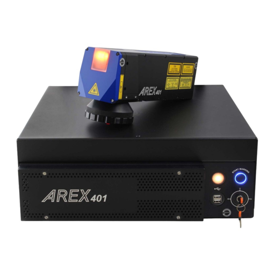
Datalogic AREX 401 User Manual (148 pages)
InfraRed Fiber Laser Marker
Brand:
Datalogic
| Category:
Measuring Instruments
| Size: 28.68 MB
Table of Contents
Table of Contents
3
About this Manual
7
Manual Conventions
7
Preface
7
Support through the Website
7
Technical Support
7
Warranty
8
Chapter 1. Introduction
9
General
9
Model Description
10
CE Compliance
11
FCC Compliance
11
EAC Compliance
11
UL Compliance
12
Laser Standards
13
Overview
14
Laser Source
14
Galvanometric Scan Head
14
Operation of a Laser Marker with Galvanometric Scanning
14
Marking Software
14
Important Warnings
15
Chapter 2. Installation
16
Unpacking
16
Contents of the Packaging
18
On Moisture Condensation
19
Note on Moisture Condensation
19
If Moisture Condensation Occurs
19
How to Avoid Moisture Condensation
19
Fixing and Positioning
20
Control Rack Installation
21
Horizontal Installation
21
Vertical Installation
23
Control Rack Mounting Screws Length
24
Scan Head Installation
25
Scan Head Mounting Screws Length
27
Installation Environment
28
Control Rack
28
Scan Head
29
Fume / Dust Extractor
29
Chapter 3. Technical Specifications
30
Technical Characteristics
30
Product Description
32
Control Rack
32
Scan Head
33
Marking Area Specification
34
F-Theta Scan Lens
35
Green Spot
36
Connectors Specifications
37
X3 - SLO (Safe Laser Off)
37
Control Rack Back Panel Connector
37
Input
38
Output
38
SAFETY_FDBK Output Status
39
SLO External Connector
40
SLO Muting Device
40
X1 - Command Box (Laser Control)
41
Control Rack Back Panel Connector
41
Muting Device
43
X2 - Axes (I/O Control)
44
Control Rack Back Panel Connector
44
Encoder
46
Control Rack Back Panel Connector
46
Photocell
46
Device Port 1
47
Control Rack Back Panel Connector
47
Device Port 2
47
Rs232 (Com3)
48
Control Rack Back Panel Connector
48
Ext Focus
48
Scan Head Connector
48
Input/Output Specifications
49
Digital Input
49
Digital Output
50
NPN Configuration (Default)
50
Laser Marker States
51
Normal Operation States
51
Error States
51
Warning State
52
Control the Laser Marker States
53
Key Selector Mode
53
Command Box Mode
53
Operating Modes
54
Timing Diagrams
55
Turning on Sequence
55
Marking Control Signals Behavior
55
SW_READY Output Signal (Ready to Mark Mode)
56
MARKING_KO Output Signal
56
SYSTEM_ALARM Output Signal
56
MARVIS™ I/O Signals Behavior
57
Safety Functions Behavior
57
INTERLOCK Behavior
57
LASER_STOP Behavior
57
Green Spot Behavior
58
System Ready to Mark Mode
58
Marking Confirmation Mode
58
MARVIS™ Verification Mode
58
Axes I/O Signals Behavior
59
Lighter™ Suite Marking Software
60
Chapter 4. Set up
62
Connections
62
Connecting X1 - Command Box Connector
62
Connecting X3 - SLO Connector
63
Connecting Power Supply Cable
64
Connecting the Earth Ground
64
Local Mode Control Connections
65
Remote Mode Control Connection
67
F-Theta Scan Lens Protection Cap Removal
68
Chapter 5. Use and Operation
69
Turning on Sequence
70
Sequence Using Key Selector
70
Sequence Using X1 - Command Box Connector
73
Chapter 6. Customize the Laser Marker Software
75
System Protection
75
System Protection Tool
75
How to Use the System Protection Tool
76
Change O.S. Language and Keyboard Layout
79
Change the LAN Configuration and IP Address
82
Change the Video Setting
85
Remote Desktop Connection
87
Chapter 7. Accessories
88
Control Box
88
Remote Start Foot Switch
89
I/O Interface
89
DB25-To-Free Leads Cable
90
MARVIS™ Add-On
90
MARVIS™ Mounting Bracket for M and L Lenses
91
Micrometric Distance Sensor Kit
91
F-Theta Protective Cap for M Lenses
92
Rack Handles
92
Fume Extractor
92
Chapter 8. Technical Support
93
Seals
93
Maintenance
94
F-Theta Scan Lens Cleaning Procedure
94
Air Filter Cleaning Procedure
95
Troubleshooting
96
Service Interface
96
List of Warning and Error States
98
List of Problems Related to Laser Marker States
99
List of most Common Problems
99
Remote Assistance
102
Appendix Alabels
103
Labels
103
Positioning of External Labels
104
Positioning of Labels on the Control Rack
104
Positioning of Labels on the Scan Head
105
Safety Labels in Local Languages
105
Appendix B. Understanding Slo: Safe Laser off Safety Considerations Ac- Cording to en Iso 13849-1:2015
106
Machine Safety
106
Risk Assessment
107
Performance Level (PL)
108
Datalogic Laser Markers
108
SLO Connection Diagram
109
Safety Functions
109
Example 1
110
Example 2
111
Example 3
112
SLO Integration Example
113
Appendix C. Laser Safety
114
Laser Radiation
114
Absorption of Laser Radiation
116
Classification and Danger Level
117
Degree of Risk with Radiation Viewing Conditions
117
Direct Viewing of the Laser Beam
117
Viewing of a Laser Reflected Beam
118
Viewing of Direct Laser Beam from a Fiber Output
118
Viewing of Scattered Laser Beam
118
Determination and O.D. of Protection Goggles
119
EN207 and EN208
120
Eyes and Skin Risks
121
General Safety Regulations
121
Other Risks
121
Appendix D. Using Marking Software
122
How to Create and Edit Graphics Layout
122
How to Test and Mark Layout
125
How to Use Command Box Signals to Mark Layout
127
Appendix E. Marking Software Upgrade
129
How to Update the Marking Software
129
Appendix F. Recover the Laser Marker
135
Overview
135
How to Recover the Laser Marker
135
Recover the System
136
New Hardware Configuration
142
Customize the Marking Software
143
Appendix G. Mechanical Drawings
145
Control Rack
146
Scan Head
147
Advertisement
Advertisement
Related Products
Datalogic Arex 400
Datalogic Arex 420
Datalogic AccuLazr AL5010
Datalogic A30
Datalogic AMT58*-PN Series
Datalogic Accu-Sort AccuVision AV6010
datalogic AV7000
Datalogic Jota A6 Touch
Datalogic AMT58-H15 16x14 CB
Datalogic AV500
Datalogic Categories
Barcode Reader
Scanner
Accessories
PDA
Handhelds
More Datalogic Manuals
Login
Sign In
OR
Sign in with Facebook
Sign in with Google
Upload manual
Upload from disk
Upload from URL