Daikin RKS35D3VMB Manuals
Manuals and User Guides for Daikin RKS35D3VMB. We have 3 Daikin RKS35D3VMB manuals available for free PDF download: Service Manual
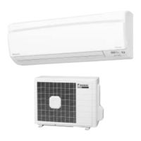
Daikin RKS35D3VMB Service Manual (228 pages)
Brand: Daikin
|
Category: Air Conditioner
|
Size: 14 MB
Table of Contents
Advertisement
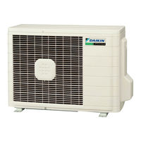
Daikin RKS35D3VMB Service Manual (184 pages)
Inverter Pair Floor / Ceiling Suspended Dual Type B-Series
Brand: Daikin
|
Category: Air Conditioner
|
Size: 6 MB
Table of Contents
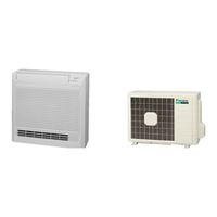
Daikin RKS35D3VMB Service Manual (184 pages)
Inverter Pair Floor Standing Type B-Series
Brand: Daikin
|
Category: Air Conditioner
|
Size: 6 MB
Table of Contents
Advertisement
Advertisement