Sign In
Upload
Manuals
Brands
Daikin Manuals
Fan
AVS
Daikin AVS Manuals
Manuals and User Guides for Daikin AVS. We have
2
Daikin AVS manuals available for free PDF download: Installation And Maintenance Manual, Installation Manual
Daikin AVS Installation Manual (60 pages)
Classroom Unit Ventilators
Brand:
Daikin
| Category:
Fan
| Size: 3.51 MB
Table of Contents
Table of Contents
3
Nomenclature
4
Model AV Ceiling Unit Ventilator Data Plate Details
4
Data Plate Location
5
Receiving & Handling
5
Visible Loss or Damage
5
Concealed Loss or Damage
5
Storage
5
Lifting Unit
5
Pre-Installation Information
5
Safety
5
Pre-Installation Considerations Properly Identify Unit Ventilator(S)
6
Uncrate and Inspect the Unit Ventilator(S)
6
Wall Openings, Louvers, and Ventimatic Shutter
6
Ventimatic Shutter Assembly
6
Installing Louvers
7
Louver Details
7
Louver Installations with Typical Unit Configurations
8
Unit Configuration Type al
8
Unit Configuration Type an
9
Unit Configuration Type AK
9
Unit Configuration Type AP
9
Typical Installation Methods
10
Installing the Ventimatic Shutter
11
Before Setting the Unit in Place
12
Removing Unit from Skid
12
Mounting Holes, Piping and Electrical Knockout Locations & Dimensions
12
Drain Pan Adjustment
13
Procedure
13
Typical Floor Unit Installation
14
Typical Ventimatic Shutter & Draftstop Installation
14
Making Piping Connections
15
Unit Ventilator Installation
15
For All Systems
15
Water Coil Connections
16
2-Pipe Chilled Water/Hot Water Systems
16
For Water Systems
16
After Brazing
17
Chilled Water & Heating Coils
17
Coil Headers, Locations Heating Only
18
Cooling Only
18
Direct Expansion Coils & Heating Coils
19
Reheat
20
Typical Valve Packages
21
Face and Bypass - Microtech II
21
2-Way and 3-Way End-Of-Cycle Valves
21
2-Way and 3-Way Modulating Valves - Microtech II
22
Modulating Valve Specifications - Microtech II
22
Steam Modulating Valve Selection - Microtech II
23
Hot Water and Chilled Water Valve Selection - Microtech II
23
Typical Piping Arrangements
24
Heating - Hot Water End of Cycle Valve Piping
24
Cooling - Chilled Water End of Cycle Valve Piping
24
Typical Water Coil Piping-EOC Valve Piping
25
Steam-Typical Modulating Valve Piping
25
For Steam Systems
26
The Optional Factory-Supplied Daikin Microtech II Modulating Control Valve
26
Typical Steam Coil Piping
26
Heating-Modulating Valve Piping
27
Hot Water (or 2-Pipe CW/HW) Modulating Valve Piping
27
2-Way Modulating, Normally Open, Hot Water or 2-Pipe CW/HW
27
Valve Piping (Typical)
27
3-Way Modulating, Normally Open, Hot Water or 2-Pipe CW/HW Valve Piping (Typical)
27
Cooling-Chilled Water Modulating Valve Piping 2-Way Modulating, Normally Closed, Chilled Water Valve Piping (Typical)
28
3-Way Modulating, Normally Closed, Chilled Water Valve Piping (Typical)
28
Condensate Piping
29
Direct Expansion (DX) R-22 Piping
29
Unit Ventilator Split Systems Guidelines
30
Checking System Charge
31
Determining Subcooling
31
Determining System Superheat
32
Superheat Adjustment
32
Making Control Connections
33
Microtech II Unit Mounted DDC Control Components-Models AVS
33
AVV, and AVR
34
Economizer Control Capabilities
35
Economizer for Reheat
35
Local User Interface
35
Operating Mode States (4)
35
Fan States (4)
35
Occupancy Modes (4)
35
Microtech II Wiring Diagram-Typical
36
Microtech II Unit Electrical Connections
37
Procedure
37
Microtech II Remote Wall Mounted Sensor
38
Field Wiring Remote Mounted Temperature Sensor
39
Installing the Remote Mounted Temperature Sensor
39
Digital Ready™-Face & Bypass Control Components Model AVS
42
Digital Ready Wiring Diagram-Typical
43
Digital Ready Unit Mounted Temperature Sensor Specifications
44
Digital Ready-Damper Actuator Specifications
44
Outdoor Air/Return Air Damper Actuator
44
Face & Bypass Damper Actuator
44
Digital Ready Unit Electrical Connections
45
Procedure
45
Controls by Others Components
46
Controls by Others Wiring Diagram-Typical
47
Controls by Others-Electrical Connections
48
Procedure
48
Electric Heat Wiring Diagram-Typical
49
Electric Heating-Standard Motor Capacities, Amps, Wire Sizing, and over Current Protection
50
Electric Heating-High Static Applications Capacities, Amps, Wire Sizing, and over Current Protection
51
Cabinets
52
Draftstop™ System/Window Down-Draft Installation
52
Installing Unit Ventilator End Panels
54
Prepare Unit Ventilator for Start-Up
55
Oiling the Fan Shaft Bearing
55
Installer's Responsibility
56
Filter(S)
56
Complete Check, Test and Start Procedure
56
Protect Your Investment - Read Carefully
56
Advertisement
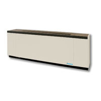
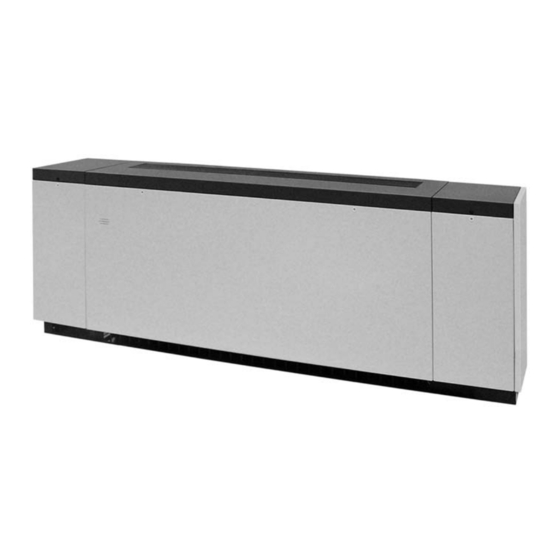
Daikin AVS Installation And Maintenance Manual (76 pages)
Classroom Unit Ventilators Floor Models Digital Ready, MicroTec Control (“J” Vintage) Field Controls by Others
Brand:
Daikin
| Category:
Fan
| Size: 5.89 MB
Table of Contents
Table of Contents
2
General Data
3
Model Nomenclature
3
Receiving & Handling
4
Visible Loss or Damage
4
Concealed Loss or Damage
4
Storage
4
Lifting Unit
4
Pre-Installation Information
5
Safety
5
Properly Identify Unit Ventilator(S)
6
Uncrate and Inspect the Unit Ventilator(S)
6
Wall Openings, Louvers, and Ventimatic™ Shutter
6
Ventimatic™ Shutter Assembly
6
Installing Louvers
7
Louver Details
7
Louver Installation with Typical Unit Configurations
8
Typical Installation Methods
10
Installing the Ventimatic Shutter Assembly
11
Before Setting the Unit in Place
12
Removing Unit from the Skid
12
Mounting Holes, Piping and Electrical Knockout Locations & Dimensions
13
Reversing Drain Pan Slope
13
Typical Floor Unit Installation
15
Unit Ventilator Installation
16
Make Piping Connections
16
Water Coil Connections
17
Coil Headers, Locations
18
Heating Only Units
18
Cooling Only Units
19
Heat/Cool Units
20
Reheat Units
22
Typical Valve Packages
23
2-Way and 3-Way Hot Water and Chilled Water Modulating Valve Selection
29
Typical Piping Arrangements
30
Heating - Hot Water End of Cycle Valve Piping
30
Cooling - Chilled Water EOC Valve Piping
31
Typical Water Coil Piping - EOC Valve Piping
31
Steam - Typical Modulating Valve Piping
32
Typical Steam Coil Piping
33
Heating - Modulating Valve Piping
34
Cooling - Chilled Water Modulating
35
Valve Piping
35
Condensate Piping
36
Unit Ventilator Split Systems Guidelines
37
Checking System Charge
38
Determining Subcooling
38
Determining System Superheat
39
Superheat Adjustment
40
Making Control Connections
40
Microtech Unit Mounted DDC Control Components - Models AVS, AVV, and AVR
40
Typical Microtech Wiring - 115Volt / 60Hz / 1 Phase
44
Microtech Unit Electrical Connections
46
Microtech Wall Mounted Sensor
47
Typical Connections for Temperature Sensor Applications
48
Making Control Connections
51
Digital Ready™ - Face & Bypass Control Components Model AVS
51
Typical Wiring Diagram
53
Digital Ready Face and Bypass Control
53
Digital Ready Unit Mounted Temperature Sensor Specifications
54
Digital Ready - Damper Actuator Specifications
55
Digital Ready Unit Electrical Connections
56
Controls by Others Components
57
Typical Controls by Others Wiring Diagram - Units with Optional EC Motor with Variable Airflow
59
Control
60
Controls by Others - Field Installed
61
Controls by Others - Electrical Connections
62
Electric Heat Wiring Diagram - Typical
64
Electric Heating
65
Draftstop™ System/Window Down-Draft Installation
67
Finned Radiation System
70
Installing Unit Ventilator End Panels
71
Prepare Unit Ventilator(S) for Start-Up
72
Oiling the Fan Shaft End Bearing
72
Unit Ventilator Start-Up
72
Filter(S)
73
Complete Check, Test and Start Procedure
73
Installer/Owner's Responsibility
73
Check, Test & Start Procedure For: Daikin Applied Unit Ventilators
74
Advertisement
Related Products
Daikin AVV
Daikin AVB
Daikin AVR
Daikin ATD03HWFAU
Daikin ATD04HWFAU
Daikin Airzone EazyZone AZEZ6DAIKSL01
Daikin Airzone EazyZone AZEZ6DAIBS07
Daikin Airzone EazyZone AZCE6LITEC
Daikin Airzone EazyZone AZX6WEBSCLOUDR
Daikin Airzone EazyZone AZX6CCP
Daikin Categories
Air Conditioner
Heat Pump
Remote Control
Chiller
Controller
More Daikin Manuals
Login
Sign In
OR
Sign in with Facebook
Sign in with Google
Upload manual
Upload from disk
Upload from URL